Table of Contents
Advertisement
Original Instruction Manual
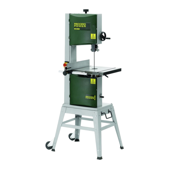
BS300E Premium
12" Bandsaw
Version 3.0
January 2013
It is important to register your product as soon as possible in order to receive efficient after sales
support and be entitled to the full 5 year guarantee. Your statutory rights are not affected.
Kg
Always wear safety glasses when
using woodworking equipment.
To register this product please visit
www.recordpower.info
Please see back cover for contact details.
i
Always read the instructions
provided before using
woodworking equipment.
Kg
Important
For your safety read instructions carefully
before assembling or using this product.
Save this manual for future reference.
Advertisement
Table of Contents

Related Manuals for Record Power BS300E Premium


Summary of Contents for Record Power BS300E Premium
- Page 1 Original Instruction Manual BS300E Premium 12" Bandsaw Version 3.0 January 2013 To register this product please visit www.recordpower.info It is important to register your product as soon as possible in order to receive efficient after sales support and be entitled to the full 5 year guarantee. Your statutory rights are not affected.
-
Page 2: Table Of Contents
Contents Terms & Conditions of Usage Explanation of Symbols General Health & Safety Guidance Additional Health & Safety for Bandsaws Record Power Guarantee User Manual Getting To Know Your Bandsaw Machine Specification Stand & Wheel Kit Assembly Machine Assembly Setting Table Square To Saw Blade Bandsaw Blade Set Up Drive Belt Adjustment &... -
Page 3: Explanation Of Symbols
Explanation of Symbols THE SYMBOLS AND THEIR MEANINGS SHOWN BELOW MAY BE USED THROUGHOUT THIS MANUAL. PLEASE ENSURE THAT YOU TAKE THE APPROPRIATE ACTION WHEREVER THE WARNINGS ARE USED. Mandatory Instructions Read and fully understand the instruction manual before attempting to use the machine. Indicates an instruction that requires particular attention Wear protective eyewear Use respiratory protective equipment... -
Page 4: General Health & Safety Guidance
General Health & Safety Guidance Ensure that you carefully read and fully understand the • If the machine is suitable to be used on a workbench, ensure that the instructions in this manual before assembly, installation and workbench is well constructed and capable of withstanding the weight use of this product. - Page 5 General Health & Safety Guidance - cont. of children. Do not allow persons unfamiliar with these instructions or • When feeding the work piece towards the blade or cutting tool never with the machine to operate it. position your hands in direct line of the cutting path. Avoid awkward operations and hand positions where a sudden slip could cause your 14.
-
Page 6: Additional Health & Safety For Bandsaws
General Health & Safety Guidance - cont. • A guard or other part that is damaged should be properly repaired 32. Have your machine repaired by a qualified person or replaced by a qualified person unless otherwise indicated in this •... -
Page 7: Record Power Guarantee
Guarantee should be made directly to Record Power or its Authorised Distributor Record Power guarantees that for a period of 5 years from the date (for details of the Authorised Distributor in your country please see of purchase the components of qualifying Products (see clauses 1.2.1 your Product manual or check www.recordpower.info for details). -
Page 8: Getting To Know Your Bandsaw
1. Getting To Know Your Bandsaw Fig.1 Blade Tensioning Knob Belt Tension & Speed Change Handle Rise & Fall Hand Wheel Blade Tension Indicator Blade Rise & Fall Lock Knob Upper Blade Guides Blade Tracking Knob Table Table Tilting Knob Rip Fence Motor Rating Plate Rip Fence Rail... -
Page 9: Stand & Wheel Kit Assembly
3. Stand & Wheel Kit Assembly 3.1 Stand & Wheel Kit Assembly Fig.3.1 CAUTION! The machine is heavy. Additional help or a suitable lifting device or support will be required for lifting the machine onto the stand. The stand and wheel kit comes as a self assembly unit Fig.3.1. Stand 1. - Page 10 3. Stand & Wheel Kit Assembly - cont. Fig.3.2 Fig.3.6 LONG MID BRACE SUPPORTS Note: When assembling this legstand do not fully tighten the nuts and bolts until the assembly is complete. When fitting the optional pedal wheel kit during initial assembly of the bandsaw, please do so before attaching the bandsaw to the leg stand to ensure greater safety and ease of fitment.
- Page 11 3. Stand & Wheel Kit Assembly - cont. 3.3 Wheel Kit Assembly Fig.3.8 1. Attach the casters to the rear legs of the machine stand using the M6 x 16 hex bolts, Washers, and M6 nuts provided. Fig 3.8. 2. Assemble the D-handle to the front short top brace of the stand, using the D-handle brackets, M6 x 16 Hex bolts, Washers and M6 Nuts provided.
- Page 12 3. Stand & Wheel Kit Assembly - cont. 1. Feed the long fixing bolts up through the Fig.3.10 stand and secure the four corners using the washers and bolts provided Fig.3.10. The whole LONG FIXING BOLTS stand can now be fully tightened ready for the bandsaw to be fitted.
-
Page 13: Machine Assembly
4. Machine Assembly 4.1 Unpacking and components included Fig.4.1 The machine is supplied partly assembled. Prior to use, further assembly is required. When unpacking the machine the following components are included for the initial assembly Fig.4.1: 1. 2 x Nuts and 1 x small crank handle 2. - Page 14 4. Machine Assembly - cont. 4.2 Rise & fall hand wheel Fig.4.2 Attach the rise and fall hand wheel to the rise and fall shaft and tighten the socket head bolt with a 6 mm allen key. Then attach the handle and RISE &...
- Page 15 4. Machine Assembly - cont. 4.6 Assembling the mitre fence Fig.4.7 Mitre Fence 1. Unscrew the locking nuts from the mitre fence Fig.4.7. 2. Place the protractor with the flat edge running parallel to the mitre fence. Fence Screws 3. Position it in such a way that the fence screws slot into the holes on the protractor Fig.4.8.
- Page 16 4. Machine Assembly - cont. 4.7 Fixing the fence bar Fig.4.11 FIXING NUTS & Place the fence bar on to the table as shown in Fig 4.11, ensuring 2 WASHERS washers are placed next to the fixing nuts. Use the 2 remaining nuts and washers to secure the fence bar from the underside of the table, Fig 4.12.
- Page 17 4. Machine Assembly - cont. 4.9 Fitting the fence carrier Fig.4.14 Locate the fence carrier on to the fence rail Fig.4.14. 4.10 Fitting the rip fence Now slide the rip fence on to the fence carrier and tighten the holding fixtures.
-
Page 18: Setting Table Square To Saw Blade
5. Setting Table Square to Saw Blade Fig.5.1 CAUTION! Before carrying out any adjustments or maintenance ensure that the machine is isolated and disconnected from the electricity supply. 5.1 Setting the table stop at 90º to saw Blade Tools Required:- Small 90º square (Not supplied) The table can be set at 90º... -
Page 19: Bandsaw Blade Set Up
6. Bandsaw Blade Set Up Fig.6.1 BLADE TENSIONING KNOB CAUTION! Before carrying out any adjustments or maintenance ensure that the machine is isolated and disconnected from the electricity supply. 6.1 Tensioning the blade BLADE TENSION INDICATOR The blade tensioning knob should be used to increase or decrease tension (See Fig. - Page 20 6. Bandsaw Blade Set Up - cont. Fig.6.5 GUIDE CARRIER CAUTION! Before carrying out any adjustments or maintenance ensure that the machine is isolated and disconnected from the LOCKING NUT electricity supply. 6.3 Adjusting the Upper Guides First check that all of the roller guides are moving freely. To adjust the upper blade guides, first position the guide assembly relative to the ROLLER GUIDES blade, by slackening off the hex screw (Fig.6.5, A) and moving the guide...
-
Page 21: Drive Belt Adjustment & Speed Change
7. Drive Belt Adjustment & Speed Change Fig.7.1 CAUTION! Before carrying out any adjustments or maintenance ensure that the machine is isolated and disconnected from the electricity supply. 7.1 Adjusting the drive belt tension Use the belt tensioning handle (See Fig.7.1) to adjust the tension of the drive belt. -
Page 22: Operation & Bandsawing Practice
Remove the faulty component and replace only with genuine Record Power replacement parts. Any electrical components should only be replaced by a suitably qualified person. - Page 23 8. Operation & Bandsawing Practice - cont. Blade Selection (TPI) - Cont. Material Material Thickness <6mm 6-12 mm 12-25 mm >25 mm Having selected an appropriate blade for the particular thickness and type Perspex 16 TPI 14 TPI of material to be sawn, it is essential that the saw blade is allowed to cut Chipboard 6 TPI 3-6 TPI...
- Page 24 4 TPI As well as the blades listed, we can also Blade Spec Blade Spec Blade Spec Material supply bandsaw blades to almost any specification - please call Record Power General width widths widths customer services in your country. 1/4”...
- Page 25 8. Operation & Bandsawing Practice - cont. Custom Jigs & Work Support A bandsaw is one of the most versatile machines in the workshop and with careful preparation many problems encountered on a job can be overcome. By making and using custom jigs repetitive and accurate work can easily be achieved, the following illustrations are some examples of typical jigs and supports used on a bandsaw.
-
Page 26: Dust Extraction
20 minutes every hour. 0.5 micron filtration Record Power offer a range of high quality dust extractors, we offer both drum and bag type extractors which filter down 0.5 micron providing CX2600 Chip Collector protection from harmful fine dusts. -
Page 27: Maintenance
10. Maintenance Fig.10.1 HEX SCREW CAUTION! Before carrying out any adjustments or maintenance ensure that the machine is isolated and disconnected from the electricity supply. KEEP PLATE 10.1 Replacing the bandsaw blade Fig.10.2 HAZARD! Take great care when unpacking the bandsaw blade as they are usually folded and can spring out very suddenly with great force. - Page 28 10. Maintenance - cont. Fig.10.4 CAUTION! Before carrying out any adjustments or maintenance ensure that the machine is isolated and disconnected from the electricity supply. CIRCLIP 10.2 Replacing the drive belt To replace the drive belt simply loosen the tension on the belt using the tension handwheel.
- Page 29 10. Maintenance - cont. 10.4 The table insert Fig.10.9 The table insert on a bandsaw is a consumable item Fig.10.9 and will therefore need replacing periodically. This procedure should be carried out with the bandsaw blade removed. To replace the table insert simply push the old insert out from underneath the table and fit the new one into position.
-
Page 30: Troubleshooting
11. Trouble Shooting WARNING: for your own safety, always turn off and unplug the machine before carrying out any troubleshooting. Symptom Possible Causes Solutions Will not cut in a straight line. 1. Blade is worn. 1. Change blade. 2. Guide carrier set too high. 2. -
Page 31: Electrical Connection & Wiring Diagram
12. Electrical Connection & Wiring Diagram Machines supplied for use in the UK are fitted with a 3 pin plug conforming machine. If replacing the original fuse, always fit a fuse of equivalent rating to BS1363, fitted with a fuse conforming to BS1362 and appropriate to the to the original. -
Page 32: Parts Diagrams
13. Parts Diagrams Stand with wheel kit Parts Diagrams Ref No. Description Ref No. Description 2 x D-handle clamps Rubber shoe Hex nut Short mid brace support Wheel bracket Hex bolt Long top brace support Hex nut Hex nut Flat washer Washer Washer Hex bolt... - Page 33 13. Parts Diagrams - cont.
- Page 34 13. Parts Diagrams - cont.
- Page 35 13. Parts Diagrams - cont.
-
Page 36: Parts List
14. Parts List Ref No. Description Ref No. Description Blade tension knob Crank handle Frame Crank Set screw M5 0.8 x 10 Guide post lock knob Safety switch Blade tracking knob Blade tensioner Wing nut M8 Washer Hex nut Hex nut M8 1.25 Sliding shaft Blade tensioner Tension wheel... - Page 37 14. Parts List - cont. Ref No. Description Ref No. Description Lock handle Rip fence Hex socket screw Hex socket screw Pointer Lock knob Trunnion plate Scale seat Guide post handwheel handle Washer Hex bolt M8 1.25 x 16 Hex socket screw Carriage bolt M6 1.0 x 65 Bush Table...
- Page 38 15. Assembly of the Optional BS300A Pedal Wheel Kit Fig.15.1 Pedal Flat washer Hex nut Spring washer Washer Axle Split pin Rotating casters Hex bolt Casters Release catch Hex nut Flat washer Operating frame Brace support bar When fitting the optional pedal wheel kit during initial assembly 7.
- Page 39 OPERATING FRAME Fig.15.2 Fig.15.10 Fig.15.6 FIXING PIN FLATTENED AREAS RELEASE CATCH PEDAL Fig.15.11 Fig.15.3 Fig.15.7 PEDAL AXLE RELEASE CATCH FIXING PIN Fig.15.8 Fig.15.4 REAR OF BANDSAW Fig.15.5 Fig.15.9 AXLE BRACE SUPPORT BAR...
- Page 40 EU Declaration of Conformity Cert No: EU / BS300E / 1 RECORD POWER LIMITED, Unit B, Ireland Industrial Est. Adelphi Way, Staveley, Chesterfield S43 3LS declares that the machinery described:- Type: Bandsaw Model No: BS300E Serial No ................. Conforms with the following directives:-...
- Page 41 Woodworking Machinery & Accessories United Kingdom Eire Australia New Zealand Record Power Ltd Record Power Ltd Tools 4 Industry Tools 4 Industry Unit B Adelphi Way, Ireland Unit B Adelphi Way, Ireland Po Box 3844 Po Box 276079 Industrial Estate, Staveley,...
Need help?
Do you have a question about the BS300E Premium and is the answer not in the manual?
Questions and answers