Table of Contents
Advertisement
PK
001810
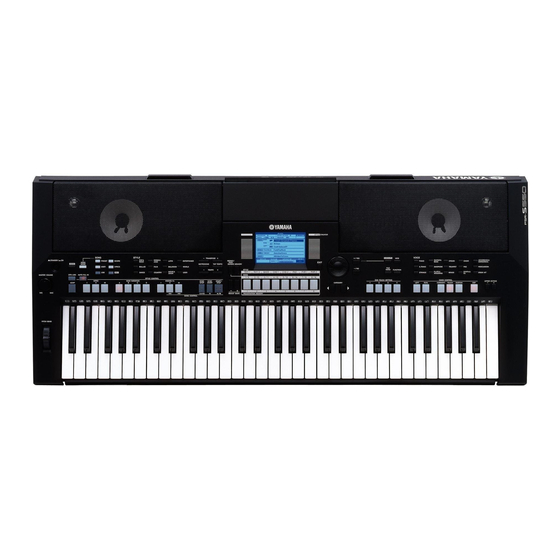
PSR-S550
CONTENTS
SPECIFICATIONS ..................................................................... 3
PANEL LAYOUT ........................................................................ 4
TEST PROGRAM ................................................................... 33
INITIALIZATION ...................................................................... 37
DATA BACKUP ........................................................................ 38
SYSTEM BOOTING FLOW CHART ....................................... 43
MIDI DATA FORMAT ............................................................... 45
OVERALL CIRCUIT DIAGRAM
SERVICE MANUAL
PSR-S550B
.............................................. 7
...................................... 21
Copyright (c) Yamaha Corporation. All rights reserved.
................................... 6
........................... 8
.............................. 9
............................. 16
20
..................... 44
HAMAMATSU, JAPAN
'08.08
Advertisement
Table of Contents

Related Manuals for Yamaha PSR-S550


Summary of Contents for Yamaha PSR-S550
-
Page 1: Table Of Contents
TEST PROGRAM ..............33 INITIALIZATION ..............37 DATA BACKUP ................ 38 SYSTEM BOOTING FLOW CHART ........43 MIDI IMPLEMENTATION CHART ..... 44 MIDI DATA FORMAT ............... 45 PARTS LIST OVERALL CIRCUIT DIAGRAM 001810 HAMAMATSU, JAPAN Copyright (c) Yamaha Corporation. All rights reserved. ’08.08... -
Page 2: Specifications
IMPORTANT NOTICE This manual has been provided for the use of authorized Yamaha Retailers and their service personnel. It has been assumed that basic service procedures inherent to the industry, and more specifically Yamaha Products, are already known and understood by the users, and have therefore not been restated. -
Page 3: Specifications
• Polyphony: 64 • 25W • LEFT Power Supply • DUAL • Adaptor: Yamaha PA-301 or PA-300 AC power adaptor Style Dimensions (W x D x H) • 176 • 946 x 402 x 130 mm (37-1/4" x 15-7/8" x 5-1/8") •... -
Page 4: Panel Layout
PSR-S550/PSR-S550B ■ PANEL LAYOUT • Front Panel [STANDBY/ON] switch [MASTER VOLUME] control [DEMO] button [SONG MODE] button SONG [PRESET], [USER], [SCOPE] [LYRICS] buttons [USB] button [REC] button STYLE STYLE CONTROL [OTS LINK], [AUTO FILL IN], [ACMP] INTRO[I]-[III], MAIN VARIATION [A]-[D] ENDING/rit. - Page 5 PSR-S550/PSR-S550B @4 @5 Rear Panel Dial [+/YES] and [-/NO] buttons CATEGORY [ ] and [ ] buttons [EXECUTE] button [MDB] button [FILE MENU] button [FUNCTION] button ONE TOUCH SETTING [1] - [4] buttons VOICE VOICE CONTROL [LEFT], [DUAL], [HARMONY], [TOUCH]...
-
Page 6: Circuit Board Layout & Wiring
PSR-S550/PSR-S550B ■ CIRCUIT BOARD LAYOUT & WIRING • Upper Case Assembly Ass’y JACK W401 • Lower Key Bed Assembly Ass’y... -
Page 7: Extension Cable For Service Use
PSR-S550/PSR-S550B No. Ref. Part No. Assembly Destination Remarks (WH33630) JACK-CN453 SP(WF) WJ465900 FFC4 PNL-CN102 PNR-CN301 WJ466000 FFC5 PNC-CN202 PNL-CN101 WQ075900 FFC2 DM-CN701 PNL-CN103 WJ465800 FFC3 DM-CN901 AM-CN104 (WJ46010) JKAM AM-CN101 JACK-CN451 WJ465600 FFC1 DM-CN501 JACK-CN403 WH336400 AM-CN102 WE13850R DM-CN801 61H-CN1... -
Page 9: Disassembly Procedure
PSR-S550/PSR-S550B ■ DISASSEMBLY PROCEDURE CAUTION: • Be sure to attach the removed filament tape just as it was before removal. • Contacts are visible from the back. Pay attention not to insert and install the cable to the connector inversely. - Page 10 PSR-S550/PSR-S550B AM Circuit Board (Time required: About 3 minutes) Remove the lower case assembly. (See procedure 1.) Remove the five (5) screws marked [380B]. The AM circuit board can then be removed. (Fig.3) JACK Circuit Board (Time required: About 3 minutes) Remove the lower case assembly.
- Page 11 PSR-S550/PSR-S550B DM Circuit Board (Time required: About 4 minutes) Remove the lower case assembly. (See procedure 1.) Remove the AM circuit board. (See procedure 2.) Remove the four (4) screws marked [380E]. The DM circuit board can then be removed. (Fig.4) As for the screw marked [380E] at the location of “A”, it...
- Page 12 PSR-S550/PSR-S550B PSW Circuit Board (Time required: About 3 minutes) Remove the lower case assembly. (See procedure 1.) Remove the two (2) screws marked [380C]. The PSW circuit board can then be removed. (Fig.3) Pull out the push knob (black) from the PSW circuit board.
- Page 13 PSR-S550/PSR-S550B PNC Circuit Board (Time required: About 6 minutes) 9-7-1 Remove the AM circuit board. (See procedure 2.) 9-7-2 Remove the DM circuit board. (See procedure 4.) 9-7-3 Remove the ten (10) screws marked [380J]. The PNC circuit board can then be removed. (Fig.4)
- Page 14 PSR-S550/PSR-S550B Rubber Contact 12P Rubber Contact 12P Rubber Contact 13P [100A] [100B] [110B] [110A] Lower Key Bed Assembly Keyboard Assembly [120B] [120A] [120A] [120A] [120A] [120A] B2 C3 B3 C4 B4 C5 B5 C6 One octave One octave One octave...
- Page 15 PSR-S550/PSR-S550B When installing the 61L circuit board (MK-L), tighten the screws 1 through 12 in numerical order as shown in the figure "61L" in Fig.10. (Fig.10) 11-7 61H Circuit Board (MK-H) (Time required: About 6 minutes) 11-7-1 Remove the white and black keys from C4 to C6. (See Fig.8 and Procedure 11-4.)
-
Page 16: Lsi Pin Description
PSR-S550/PSR-S550B ■ LSI PIN DESCRIPTION CONTENTS ● AK4385ET (X6040A01) DAC ..................16 MN101C027YB (XS71120R) CPU ................16 ● ● R8A0232BG (X8810A00) CPU (SWX02) ..............17 ● S1D13700F01A100 (X5422A00) LCD CONTROLLER ..........19 ● UPD789022GB-A15-8E (XZ56010R) CPU (MKS) ............19 AK4385ET (X6040A01) DAC (Digital to Analog Converter) - Page 17 PSR-S550/PSR-S550B R8A02032BG ( X8810A00 ) CPU ( SWX02 ) DM: IC7 OUTER OUTER NAME FUNCTION NAME FUNCTION Ground VSSPLL PLL analog ground ADC analog input 2 Wave memory data bus 6 ADC analog input 1 Wave memory data bus 7...
- Page 18 PSR-S550/PSR-S550B OUTER OUTER NAME FUNCTION NAME FUNCTION MA15 Wave memory address bus 15 Parallel port A6 MA16 Wave memory address bus 16 Parallel port A7 MA17 Wave memory address bus 17 VCCQ Power supply +3.3 V MA18 Wave memory address bus 18...
- Page 19 PSR-S550/PSR-S550B S1D13700F01A100 (X5422A00) LCD CONTROLLER DM: IC4 NAME FUNCTION NAME FUNCTION Ground Ground AB12 XCD1 Drain output AB11 XCG1 Gate input AB10 Address bus RESET# Reset SCANEN Test mode set up input TESTEN HIOVDD Power supply CLKI Externally sourced system clock...
-
Page 20: Ic Block Diagram
PSR-S550/PSR-S550B ■ IC BLOCK DIAGRAM SN74LV08APWR (X4463A00) SN74LV14APWR (X6688A0R) NJM4580E(TE2) (X2331A0R) DM: IC13 Hex Inverter Dual Operational Amplifier SN74AHCT08PWR (X3824A00) DM: IC20 DM: IC16 DM: IC24 Quad 2 Input AND +DC Voltage Output A Supply Inverting Output B Input A... -
Page 21: Circuit Boards
PSR-S550/PSR-S550B ■ CIRCUIT BOARDS CONTENTS ● 61H Circuit Board (X2335C0) ..................32 ● 61L Circuit Board (X2336B0) ..................32 ● AM Circuit Board (X7722C0) ..................24 DM Circuit Board (X9574B0) ..................22 ● ● ENC Circuit Board (X7722C0) ..................25 ●... - Page 22 PSR-S550/PSR-S550B DM Circuit Board ● to PNL-CN103 to LCD Unit to AM-CN104 to 61L-CN5 Not installed to 61H-CN1 Not installed to 61H-CN2 to JACK-CN403 to ENC-CN301 Component Side 2NA-WH33370...
- Page 23 PSR-S550/PSR-S550B DM Circuit Board ● Pattern Side 2NA-WH33370...
- Page 24 PSR-S550/PSR-S550B AM Circuit Board ● to LCD Backlight MVR Circuit Board ● MASTER VOLUME Component Side PB Circuit Board ● PITCH BEND Component Side Component Side 2NA-WH33410 MVR: 2NA-WH33410 2NA-WH33410...
- Page 25 PSR-S550/PSR-S550B JACK Circuit Board ● PSW Circuit Board ● STANDBY/ON Component Side ENC Circuit Board ● to DM-CN702 Rotary Encoder Component Side TW Circuit Board ● TWL: to Tweeter L TWL: to Tweeter R Component Side Component Side JACK: 2NA-WH33410...
-
Page 26: Pnl Circuit Board
PSR-S550/PSR-S550B PNL Circuit Board ● SONG PRESET STYLE POP & ROCK SWING & JAZZ SCORE DEMO SONG MODE BALLAD LYRICS USER R & B COUNTRY DANCE OTS LINK AUTO FILL IN VARIATION D INTRO 2 INTRO 3 VARIATION A VARIATION B... - Page 27 PSR-S550/PSR-S550B PNL Circuit Board ● to PNC-CN202 to PNR-CN301 to DM-CN701 Pattern Side 2NA-WH33400...
- Page 28 PSR-S550/PSR-S550B PNC Circuit Board ● REGIST/ PART MEMORY MEMORY 3 MEMORY 4 MEMORY 5 MEMORY 6 MEMORY 7 REGIST BANK MEMORY 1 MEMORY 2 +/YES EXIT -/NO MEMORY 8 CATEGORY CATEGORY Component Side 2NA-WH50940...
- Page 29 PSR-S550/PSR-S550B PNC Circuit Board ● to PNL-CN101 Pattern Side 2NA-WH50940...
- Page 30 PSR-S550/PSR-S550B PNR Circuit Board ● GUITAR & EXECUTE PIANO BASS SAXOPHONE E.PIANO FILE MENU FUNCTION STRINGS FLUTE & WOODWIND MEMORY 7 ONE TOUCH 2 ONE TOUCH 3 ONE TOUCH 4 LEFT DUAL ONE TOUCH 1 ACCORDION & HARMONICA CHOIR ORGAN...
- Page 31 PSR-S550/PSR-S550B PNR Circuit Board ● to PNL-CN102 Pattern Side 2NA-WH50940...
- Page 32 PSR-S550/PSR-S550B 61H Circuit Board to DM-CN801 to 61L-CN4 to DM-CN803 61L Circuit Board to DM-CN802 to 61H-CN3 61H: 2NAKB-V869540 61L: 2NAKB-V869520...
-
Page 33: Test Program
3) Jigs: Foot switch (FC-4 or FC-5), USB cable, USB flash memory, USB-MIDI driver (*1) PC (Install a USB-MIDI driver (*1) in PC and finish the THROUGH setup.) *1 Obtain the USB-MIDI driver from CD-ROM(X9448A00) for PSR-S550/PSR-S550B or Yamaha official website. (URL>>http://www.yamahapkclub.com) HOW TO ENTER THE TEST PROGRAM While pressing the C2#, F2 and G2# keys, turn the [STANDBY/ON] switch on. - Page 34 PSR-S550/PSR-S550B D. Test Item List TEST LCD Display Test Descriptions, Judgment Criteria 003 Ram Chk1 Checks the RAM that is connected to the CPU bus. The test results appear on the LCD. Check that the LCD displays "Ram OK". (OK:"Ram OK", NG:"Ram NG") 004 Flash Rom Chk1 Checks the flash ROM that is connected to CPU bus.
- Page 35 PSR-S550/PSR-S550B TEST LCD Display Test Descriptions, Judgment Criteria 029 Pedal4 Chk Connect the foot switch (FC-4 or FC-5) to the [SUSTAIN] jack. Check that the C3 note is output when the [START/STOP] button is pressed while stepping the pedal and the C4 note is output when releasing the pedal.
- Page 36 PSR-S550/PSR-S550B TEST LCD Display Test Descriptions, Judgment Criteria 049 Factory Set All backup domains are initialized and it changes into a factory-shipments state when executing this test. 050 Test Exit Exit from the test program after executing this test. Noise Check (in the normal mode) Connect the level meter(with a JIS-C filter) to the [PHONES/OUTPUT] jack.
-
Page 37: Initialization
PSR-S550/PSR-S550B ■ INITIALIZATION This function erases all User Songs, User Styles, User MDB, and backup data in the instrument's internal memory and restores the initial default settings and data. The following initialization procedures are provided. Backup Clear To clear backup data to the internal memory, simultaneously hold the highest white key on the keyboard and turn the power on by pressing the [STANDBY/ON] switch. -
Page 38: Data Backup
PSR-S550/PSR-S550B ■ DATA BACKUP To back up user data to an external device, use a USB flash memory. Refer to the following for the data you can back up using it. • User Songs • User Styles • User MDB •... - Page 39 PSR-S550/PSR-S550B Formatting USB Flash Memory A new USB flash memory device must be formatted before it can be used by this instrument. CAUTION Press the [EXECUTE] button again, or the • If you format a USB flash memory that already contains data, all of [+/YES] button, and the format operation will the data will be erased.
- Page 40 PSR-S550/PSR-S550B Saving the Registration Data The registration data you created in the instrument can be saved to a USB flash memory device. Make sure that a appropriately formatted USB flash memory device has been properly connected to the instrument’s USB TO DEVICE terminal, and that a “CONNECT”...
- Page 41 PSR-S550/PSR-S550B Saving a User Song or User Style This operation saves user Songs (Song numbers 001-005) or user Styles to USB flash memory. Songs are saved in SMF Format 0. What is SMF (Standard MIDI File)? To Overwrite an Existing File...
- Page 42 PSR-S550/PSR-S550B Loading Registration Files, Style Files, Song Files or MDB Files Registration files, Style files, Song files and MDB files residing on a USB flash memory can be loaded to the instrument. Use the dial to select the Registration, CAUTION Style, Song or MDB file you want to load.
-
Page 43: System Booting Flow Chart
PSR-S550/PSR-S550B ■ SYSTEM BOOTING FLOW CHART Power On E-IC = L (IC7 D12,72Pin) TxD0 = H (IC7 B7,27Pin) Access beginning to the TxD1 = H (IC7 B6,26Pin) Initialize IC9(Program Flash ROM). BACK-UP FLASH Access beginning to the (IC10) IC10(Backup Flash ROM). -
Page 44: Midi Implementation Chart
PSR-S550/PSR-S550B ■ MIDI IMPLEMENTATION CHART YAMAHA [ Digital Keyboard ] Date:11-APR-2008 Model PSR-S550 MIDI Implementation Chart Version:1.0 Transmitted Recognized Remarks Function... Basic Default 1 - 16 1 - 16 Channel Changed 1 - 16 1 - 16 Default Mode Messages... -
Page 45: Midi Data Format
PSR-S550/PSR-S550B ■ MIDI DATA FORMAT NOTE: 1 By default (factory settings) the instrument ordinarily functions <Reverb Type> F0H, 43H, 1nH, 4CH, 02H, 01H, 00H, mmH, as a 16-channel multi-timbral tone generator, and incoming llH, F7H data does not affect the panel voices or panel settings. How- •... -
Page 46: Parts List
PARTS LIST CONTENTS OVERALL ASSEMBLY UPPER CASE ASSEMBLY Ass’y KEYBOARD ASSEMBLY 16N-C61 Ass’y LOWER CASE ASSEMBLY Ass’y ELECTRICAL PARTS Note) DESTINATION ABBREVIATIONS Australian model Chinese model British model South-east Asia model Canadian model Taiwan model German model U.S.A. model European model General export model (110V) French model General export model (220V) - Page 47 PSR-S550/PSR-S550B I OVERALL ASSEMBLY Upper Case Assembly Music Rest See page 4. Lower Case Assembly See page 8. Lower key bed assembly Keyboard Assembly See page 7. L110 AC Adaptor(PA-301) This figure shows Japanese model.
- Page 48 WF49100R BIND HEAD TAPPING SCREW-B 3.0X30 MFZN2W3 WH414600 DUST PROOF CLOTH 40X22X0.5 WH347400 NONWOVEN FABRIC CLOTH GOST-R LABEL ALL COMMON E PSR-S550 Y (WN00110) LOWER KEY BED ASSEMBLY (WH08860) WD83950R LOWER CASE F WE126700 KEYBOARD ASSEMBLY 16N C61-2M WE13850R WIRING ASSEMBLY...
- Page 49 PSR-S550/PSR-S550B I UPPER CASE ASSEMBLY Ass’y 540a 540b 520c 520b 520a 385 450 310b 310a...
- Page 50 PSR-S550/PSR-S550B PART NO. DESCRIPTION REMARKS REF NO. QTY RANK UPPER CASE ASSEMBLY PSR-S550/PSR-S550B UPPER CASE ASSEMBLY PSR-S550 (WN54980) UPPER CASE ASSEMBLY PSR-S550B (WP47720) ∗ WN549900 UPPER CASE PSR-S550 ∗ WP477300 UPPER CASE PSR-S550B WH168200 SP GRILLE L ASSEMBLY LEFT PSR-S550 ∗...
- Page 51 PSR-S550/PSR-S550B PART NO. DESCRIPTION REMARKS REF NO. QTY RANK NONWOVEN FABRIC CLOTH (WG81830) WH412900 CUSHION 150X5X5 CB06925R BINDING TIE BK-1 WJ465900 WIRING ASSEMBLY FFC4 WJ466000 WIRING ASSEMBLY FFC5 ∗ WQ075900 WIRING ASSEMBLY FFC2 FERRITE CORE 520a HF70SH11X0.7X8 (WP91500) SPONGE 520b...
- Page 52 PSR-S550/PSR-S550B I KEYBOARD ASSEMBLY 16N-C61 Ass’y Keyboard Assembly Lower Case F PART NO. DESCRIPTION REMARKS REF NO. QTY RANK KEYBOARD ASSEMBLY PSR-S550/PSR-S550B 16N C61-2M WE126700 KEYBOARD ASSEMBLY 16N C,E,G,B V3412600 WHITE KEYS 16N C,E,G,B WB12520R KEY CEGB 16L D,F,A V3412700...
-
Page 53: Lower Case Assembly
PSR-S550/PSR-S550B I LOWER CASE ASSEMBLY Ass’y L20b L20a L30b L30a Lower Case Sub Assembly... - Page 54 PSR-S550/PSR-S550B PART NO. DESCRIPTION REMARKS REF NO. QTY RANK LOWER CASE ASSEMBLY PSR-S550/PSR-S550B LOWER CASE ASSEMBLY (WP02260) ∗ WP023100 LOWER CASE SUB ASSEMBLY ∗ YA372A00 SPEAKER(WOOFER) 12.0cm 8 ohm 10W WIRING ASSEMBLY (WH33630) WE98120R BIND HEAD TAPPING SCREW-B 4.0X12 MFZN2W3...
- Page 55 PSR-S550/PSR-S550B I ELECTRICAL PARTS AM,ENC,JACK,MVR,PB,PSW,TW PART NO. DESCRIPTION REMARKS REF NO. QTY RANK ELECTRICAL PARTS PSR-S550/PSR-S550B WH334300 CIRCUIT BOARD (WH33410)(X7722C0) WH334500 CIRCUIT BOARD (WH33410)(X7722C0) WH334200 CIRCUIT BOARD JACK (WH33410)(X7722C0) WH334400 CIRCUIT BOARD (WH33410)(X7722C0) WH334700 CIRCUIT BOARD (WH33410)(X7722C0) WH334600 CIRCUIT BOARD...
- Page 56 PSR-S550/PSR-S550B AM,ENC,JACK,MVR,PB,PSW,TW PART NO. DESCRIPTION REMARKS REF NO. QTY RANK UA652470 POLYESTER FILM CAPACITOR C217 470P 50V J RX TP VC69480R C401 CEAMIC CAPACITOR 0.1000 25V Z VM902400 SEMICONDUCTIVE CERA. CAP. C401 0.1000 25V Z FORM. UA354470 POLYESTER FILM CAPACITOR C451 0.0470 50V J RX TP...
- Page 57 PSR-S550/PSR-S550B AM,ENC,JACK,MVR,PB,PSW,TW,DM PART NO. DESCRIPTION REMARKS REF NO. QTY RANK VB835000 COIL L452 20uH FL05RD200AT VB835000 COIL L453 20uH FL05RD200AT VT27920R COIL L452 DX001-20UH VT27920R COIL L453 DX001-20UH HF45510R R101 CARBON RESISTOR 1/4 100.0 1/4 J AX TP V254800R R101 CARBON RESISTOR 1/6 100.0 1/6J 26TP...
- Page 58 PSR-S550/PSR-S550B PART NO. DESCRIPTION REMARKS REF NO. QTY RANK US062100 CERAMIC CAPACITOR-SL CHIP 100P 50V J RECT. WG251600 CHIP CERAMIC CAPACITOR 4.7 6.3V K RECT. US061220 CERAMIC CAPACITOR-CH CHIP 22P 50V J RECT. US061220 CERAMIC CAPACITOR-CH CHIP 22P 50V J RECT.
- Page 59 PSR-S550/PSR-S550B PART NO. DESCRIPTION REMARKS REF NO. QTY RANK US064100 CERAMIC CAPACITOR-B (CHIP) -223 0.0100 50V K RECT. US064100 C225 CERAMIC CAPACITOR-B (CHIP) 0.0100 50V K RECT. US062470 CERAMIC CAPACITOR-SL CHIP C230 470P 50V J RECT. US062470 CERAMIC CAPACITOR-SL CHIP C231 470P 50V J RECT.
- Page 60 PSR-S550/PSR-S550B PART NO. DESCRIPTION REMARKS REF NO. QTY RANK VY65720R CHIP INDUCTANCE 600 BK1608HM601-T WG595200 CHIP INDUCTANCE GZ1608D601 1608 V858970R CHOKE COIL 330U SLF7045T-331M VY65720R CHIP INDUCTANCE 600 BK1608HM601-T WG595200 CHIP INDUCTANCE GZ1608D601 1608 V270320R CHIP INDUCTANCE BLM18BB221SN1D V270320R CHIP INDUCTANCE...
- Page 61 PSR-S550/PSR-S550B PART NO. DESCRIPTION REMARKS REF NO. QTY RANK RD356560 CARBON RESISTOR 1/16 CHIP R110 5.6K 63M J RECT. RD356560 CARBON RESISTOR 1/16 CHIP -113 5.6K 63M J RECT. RD356100 CARBON RESISTOR 1/16 CHIP R114 1.0K 63M J RECT. RD356100...
- Page 62 PSR-S550/PSR-S550B DM,PNL PART NO. DESCRIPTION REMARKS REF NO. QTY RANK RD35422R CARBON RESISTOR 1/16 CHIP R235 22.0 63M J RECT. RD35422R R236 CARBON RESISTOR 1/16 CHIP 22.0 63M J RECT. RD35422R CARBON RESISTOR 1/16 CHIP R239 22.0 63M J RECT.
- Page 63 PSR-S550/PSR-S550B PNL,PNC,PNR,61L,61H PART NO. DESCRIPTION REMARKS REF NO. QTY RANK RD35747R CARBON RESISTOR 1/16 CHIP R150 47.0K 63M J RECT. RD35747R CARBON RESISTOR 1/16 CHIP -157 47.0K 63M J RECT. RD355100 CARBON RESISTOR 1/16 CHIP R158 100.0 63M J RECT.
- Page 64 PSR-S550/PSR-S550B PART NO. DESCRIPTION REMARKS REF NO. QTY RANK ∗ YA372A00 SPEAKER(WOOFER) WN744800 LCD UNIT ∗ ∗ ∗ ∗ ∗ : New Parts RANK : Japan only...
- Page 65 < Page1 > PSR-S550/PSR-S550B PSR-S550/PSR-S550B OVERALL CIRCUIT DIAGRAM 1/5 (DM 1/2 ) CONTENTS PSR-S550/PSR-S550B OVERALL CIRCUIT DIAGRAM • 61H • PB • 61L • MVR • AM • PNC • DM 1/2 • PNL • DM 2/2 • PNR • ENC •...
-
Page 66: Psr-S550/Psr-S550B Overall Circuit Diagram
< Page2 > PSR-S550/PSR-S550B PSR-S550/PSR-S550B OVERALL CIRCUIT DIAGRAM 2/5 (DM 2/2 ) to 61H-CN2 to 61L-CN5 to 61H-CN1 <Page4 C6> <Page4 C8> <Page4 C5> <Page1 D5> Not Installed to PNL-CN103 <Page5 K6> to ENC-CN301 <Page1 C6> <Page3 C6> Not Installed... -
Page 67: Enc
< Page3 > PSR-S550/PSR-S550B PSR-S550/PSR-S550B OVERALL CIRCUIT DIAGRAM 3/5 (AM, JACK, ENC, MVR, PB, PSW, TW ) JACK POWER AMP SUSTAIN TO HOST W401 to DM-CN501 <Page1 K4> 28CC1-2001009321-1 2 TO DEVICE to DM-CN901 CONTRAST <Page2 I6> DC/DC CONVERTER PITCH BEND... -
Page 68: Pnc
< Page4 > PSR-S550/PSR-S550B PSR-S550/PSR-S550B OVERALL CIRCUIT DIAGRAM 4/5 (PNC, PNR, 61H, 61L) FLUTE & SYNTH. & WOODWIND REGIST/ PART to PNL-CN101 <Page5 K2> ACCORDION & PERCUSSION HARMONICA SUSTAIN FILEMENU GUITAR & to PNL-CN102 BASS <Page5 K4> TOUCH 28CC1-2001009323-2 1... -
Page 69: Pnl
< Page5 > PSR-S550/PSR-S550B PSR-S550/PSR-S550B OVERALL CIRCUIT DIAGRAM 5/5 (PNL) to PNC-CN202 <Page4 A2> to PNR-CN301 <Page4 F3> to DM-CN701 <Page2 K2> 28CC1-2001009322 1 Ceramic Capacitor WARNING Components having special characteristics are marked and must be replaced with parts having specification equal to those originally installed.
Need help?
Do you have a question about the PSR-S550 and is the answer not in the manual?
Questions and answers
no sound from keyboard