
Related Manuals for Kenwood CK 305


Summary of Contents for Kenwood CK 305
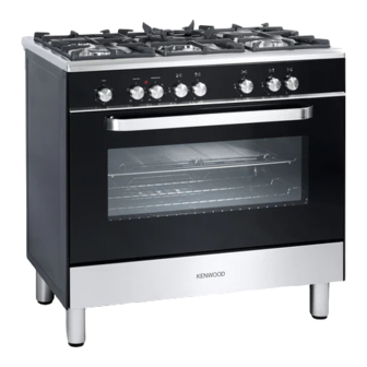
- Page 1 DUAL FUEL COOKER CK 305 model Instructions for use - Installation advice Before operating this cooker, please read these instructions carefully...
-
Page 2: Table Of Contents
CONTENTS Page Number Introduction . . . . . . . . . . . . . . . . . . . . . . . . . . . . . . . . . . . . . . . . . . . . . . . 3 Important Safeguards &... -
Page 3: Introduction
Dear Customer, Thank you for purchasing a Kenwood CK 305 dual fuel cooker. The safety precautions and recommendations reported below are for your own safety and that of others. They will also provide a means by which to make full use of the features offered by your appliance. -
Page 4: Important Safeguards & Recommendations
IMPORTANT SAFETY PRECAUTIONS AND RECOMMENDATIONS IMPORTANT: This appliance is designed and manufactured solely for the cooking of domestic (household) food and is not suitable for any non domestic application and therefore should not be used in a commercial environment. The appliance guarantee will be void if the appliance is used within a non domestic environment i.e. - Page 5 • Do not touch the appliance with wet or damp hands (or feet) . • Do not use the appliance whilst in bare feet . • If you should decide not to use this appliance any longer (or decide to substitute another model), before disposing of it, it is recommended that it be made inoperative in an appropriate manner in accordance to health and environmental protection regulations, ensuring in particular...
- Page 6 • WARNING: Danger of fire: do not store items on the cooking surfaces. • WARNING: When correctly installed, your product meets all safety requirements laid down for this type of product category . However special care should be taken around the rear or the underneath of the appliance as these areas are not designed or intended to be touched and may contain sharp or rough edges, that may cause injury .
-
Page 7: Cooking Hob
1 - COOKING HOB Fig . 1 .1 GAS BURNERS Auxiliary burner (A) 1,00 kW Semi-rapid burner (SR) 1,75 kW Rapid burner (R) 3,00 kW Triple-ring burner (TR) 3,50 kW Notes: • The electric ignition is incorporated in the knobs . •... -
Page 8: Control Panel
2 - CONTROL PANEL Fig . 2 .1 CONTROL PANEL - Controls description Front right burner control knob Rear right burner control knob Central burner control knob Rear left burner control knob Front left burner control knob Fan oven temperature control knob Fan oven function selector control knob 120 minutes timer control knob Fan oven temperature indicator light... -
Page 9: Use Of The Hob Burners
3 - USE OF THE HOB BURNERS GAS BURNERS Gas flow to the burners is adjusted by turning the knobs (illustrated in fig. 3.1) which control the safety valves . Turning the knob, so that the indicator line points to the symbols printed on the panel, achieves the following functions: - symbol closed valve... - Page 10 LIGHTING THE BURNERS CHOICE OF THE BURNER ignite burner, following On the control panel, near every knob instructions are to be followed: there is a diagram that indicates which burner is controlled by that knob . Press in the corresponding knob and The suitable burner must be chosen turn counter-clockwise (fig. 3.2) to the according to the diameter and the capacity...
- Page 11 CORRECT USE OF THE TRIPLE-RING BURNER Only flat bottom pans of the correct size are to be placed on the pan support above the Triple-ring burner . When using a WOK, the supplied wok stand must be placed onto the pan stand to avoid any faulty operation of the triple-ring burner (fig. 3.4a). The wok should not be placed directly onto the pan support without the use of the supplied wok stand (fig. 3.4b).
-
Page 12: Fan Oven
4 - FAN OVEN OPERATING PRINCIPLES Attention: the oven door becomes Heating and cooking in the FAN oven are very hot during operation. obtained in the following ways: Keep children away. a. by forced convection A fan sucks in the air contained in the oven muffle, which sends it through the circular heating element and then GENERAL FEATURES... - Page 13 Fig . 4 .1 Fig . 4 .2 TEMPERATURE KNOB (fig. 4.2) To turn on the heating elements of the oven, set the switch knob on the desired program and select the required temperature . To set the temperature, line up the temperature knob indicator with the required temperature .
- Page 14 HOT AIR COOKING The circular element and the fan are on . The heat is diffused by forced convection and the temperature must be regulated between 50° and 250 °C with the ther mostat knob . It is not necessary to preheat the oven . Recommended for: For foods that must be well done on the outside and tender or rare on the inside, i .
- Page 15 COOKING ADVICE SIMULTANEOUS COOKING STERILIZATION DIFFERENT FOODS Sterilization of foods to be conserved, in consents simultaneous full and hermetically sealed jars, is done in heterogeneous cooking of different foods . the following way: Different foods such as fish, cake and meat can be cooked together without a .
-
Page 16: Cooking Guide
5 - OVEN TEMPERATURE GUIDE Electric oven temperature Cooking process Oven heat Gas mark °C °F Keeping food hot, very cool ½ milk puddings Egg custards cool Rich fruit cakes, cool braising Low temperature moderate roasting, shortbread Victoria sandwich, plain fruit cake, moderate baked fish Small cakes, choux... -
Page 17: 120 Minutes Timer
6 - 120 MINUTE TIMER 120 MINUTE TIMER (fig. 6.1) The timer can be set to a maximum of 120 minutes and a buzzer will sound at the end of the countdown . The knob must be rotated clockwise as far as the 120 minute position first and then set to the required time by rotating it anticlockwise . -
Page 18: Cleaning & Maintenance
7 - CLEANING AND MAINTENANCE GENERAL ADVICE ENAMELLED PARTS • Before you begin cleaning, you must All the enamelled parts must be cleaned ensure that the appliance is switched with a sponge and soapy water or other off . non-abrasive products . •... - Page 19 CLEANING THE HOB CORRECT REPLACEMENT OF THE Spillage on the hob can usually be removed AUXILIARY, SEMI-RAPID AND RAPID by a damp soapy cloth . More obstinate BURNERS stains can be removed by rubbing gently It is very important to check that the burner with a soapy nylon (non metal) scouring flame distributor “F”...
- Page 20 Fig. 7.1 Fig. 7.2 Fig. 7.3 Fig. 7.5 Fig. 7.4...
- Page 21 ASSEMBLY AND DISMANTLING OF Fig. 7.6 THE SIDE RUNNER FRAMES • Fit the side runner frames into the holes on the side walls inside the oven (fig. 7.6). • Slide the rack into the runners (fig. 7 .7) . The rack must be fitted so that the safety notch, which stops it sliding out, faces the inside of the oven;...
- Page 22 Fig . 7 .9 Fig . 7 .10 OVEN DOORS STORAGE COMPARTMENT The internal glass panel can be easily The storage compartment is accessible removed for cleaning by unscrewing the through the pivoting panel (fig. 7.10). retaining screws (fig. 7.9). Do not use harsh abrasive cleaners or Do not store flammable material in the sharp metal scrapers to clean the oven oven or in the storage compartment.
-
Page 23: Removing The Oven Door
REMOVING THE OVEN DOOR The oven door can easily be removed as follows: • Open the door to the full extent (fig. 7 .11a) . • Open the lever “A” completely on the left and right hinges (fig. 7.11b). • Hold the door as shown in fig. 7.11. • Gently close the door (fig. 7.11c) until Fig . 7 .11a left and right hinge levers “A”... -
Page 24: Advice For The Installer
Advice for the installer IMPORTANT • The appliance is designed and approved for domestic use only and should not be installed in a commercial, semi commercial or communal environment . The appliance may be installed in a kitchen, Kitchen/diner or a bed sitting room, but not in a room or space containing a bath or a shower . -
Page 25: Installation
8 - INSTALLATION This cooker has class “2/1” overheating protection so that it can be installed next to a cabinet. If the cooker is installed adjacent to furniture which is higher than the gas hob cooktop, a gap of at least 200 mm must be left between the side of the cooker and the furniture . The furniture walls adjacent to the cooker must be made of material resistant to heat . - Page 26 FITTING THE ADJUSTABLE FEET AND LEVELLING THE COOKER The adjustable feet must be fitted to the base of the cooker before use (figs. 8.2, 8 .3) . Rest the rear of the cooker on a piece of the polystyrene packaging exposing the base for the fitting of the feet. Fit the 4 legs by screwing them tight into the support base as shown in figure 8.3. Fig. 8.2 Fig.
- Page 27 MOVING THE COOKER WARNING: When raising cooker to upright position always ensure two people carry out this manoeuvre to prevent damage to the adjustable feet (fig. 8.5). Fig. 8.5 WARNING WARNING Be carefull: Do not lift the cooker by When moving cooker to its final position the door handle/s when raising to the DO NOT DRAG (fig. 8.7). upright position (fig. 8.6). Lift feet clear of floor (fig. 8.5). Fig. 8.7 Fig.
- Page 28 ANTI-TILT BRACKET Important! To restrain the appliance and prevent it tipping accidentally, fit a bracket to its rear to fix it securely to the wall. To fit the anti-tilt bracket: After you have located where the cooker is to be positioned, mark on the wall the place where the two screws of the anti-tilt bracket have to be fitted. Please follow the indications given in fig. 8.8. Drill two 8 mm diameter holes in the wall and insert the plastic plugs supplied . Important! Before drilling the holes, check that you will not damage any pipes or electrical wires.
- Page 29 PROVISION FOR VENTILATION • The appliance should be installed into a room or space with an air supply in accordance with BS 5440-2: 2000 . • For rooms with a volume of less than 5m - permanent ventilation of 100 cm free area will be required .
-
Page 30: Gas Installation
9 - GAS INSTALLATION IMPORTANT NOTE This appliance is supplied for use on NATURAL GAS or LPG (check the gas regulation label attached on the appliance) . • Appliances supplied for use on NATURAL GAS: they are adjusted for this gas only and cannot be used on any other gas (LPG) without modification. The appliances are manufactured for conversion to LPG . - Page 31 GAS CONNECTION The installation of the gas appliance to Natural Gas or LP Gas must be carried out by a suitably qualified and registered installer. Installers shall take due account of the provisions of the relevant British Standards Code of Practice, the Gas Safety Regulations and the Building Standards (Scotland) (Consolidation) Regulations issued by the Scottish Development Department .
-
Page 32: Gas Connection
Gas Connection Cat: II 2H3+ The gas supply must use the nearest gas inlet pipe which is located at the left or the right hand side at the rear of the appliance (fig. 9.1). The hose should also be connected in such away that it does not touch the floor. To screw the connecting tube operate with two spanners (fig. 9.2). The unused end inlet pipe must be closed with the plug interposing the gasket . After connecting to the mains, check that the coupling are correctly sealed, using soapy solution, but never a flame. - Page 33 IMPORTANT PRESCRIPTIONS FOR GAS CONNECTION Rear wall Suggested area for gas mains connection Fig. 9.3...
- Page 34 CONVERSION TO NATURAL GAS OR TO LPG REPLACEMENT Auxiliary, INJECTORS OF THE TOP BURNERS Semi-rapid and If the injectors are not supplied they can Rapid burners be obtained from the After-Sales Service. Select the injectors to be replaced according to the “Table for the choice of the injectors”...
- Page 35 TABLE FOR THE CHOICE OF THE INJECTORS Cat: 2H3+ G30 28-30 Natural Gas mbar G20 20 mbar Nominal Reduced G31 37 mbar BURNERS power power [kW] [kW] Ø Ø injector injector [1/100 mm] [1/100 mm] Auxiliary (A) 1,00 0,30 Semi-rapid (SR) 1,75 0,45 Rapid (R)
-
Page 36: Electrical Section
10 - ELECTRICAL INSTALLATION WARNING! ELECTRICITY CAN BE EXTREMELY DANGEROUS. THIS APPLIANCE MUST BE EARTHED. The appliance must be connected to the electrical network verifying above all that the voltage corresponds to the value indicated on the specifications plate and that the cables section of the electrical plant can bear the load which is also indicated on the plate . - Page 37 Electrical feeder cable connection The operations must be executed by a qualified technician . To connect the supply cable: - Remove the screws securing the cover “A” on the rear of the cooker (fig . 10 .1) . - Unscrew cable clamp “D” (fig. 10.2). - Connect the wires to the terminal block “B”...
- Page 38 Connection to Fixed Wiring A double pole switch must be provided no further than 2 metres from the appliance to the electrical supply . The appliance should be connected to a DOUBLE POLE SWITCHED FUSED SPUR OUTLET, similar to that shown in Fig . 10 .4 . DOUBLE POLE SWITCHED FUSED SPUR OUTLET FUSE...
- Page 39 11 - GUARANTEE Your new “KENWOOD” product comes with 12-month guarantee covering all parts and labour . If your appliance proves to be defective as a result of faulty materials or workmanship during the guarantee period, these parts will be repaired or replaced free of charge .
- Page 40 The manufacturer cannot be held responsible for possible inaccuracies due to printing or transcription errors in the present booklet . The manufacturer reserves the right to make all modifications to its products deemed necessary for manufacture or commercial reasons at any moment and without prior notice, without jeopardising the essential functional and safety characteristics of the appliances . Code: 1104329 - ß3...
Need help?
Do you have a question about the CK 305 and is the answer not in the manual?
Questions and answers