Lenovo ThinkCentre M83 Hardware Maintenance Manual
Machine types: 10a0, 10a1, 10a2, 10a3, 10a4, 10a5, 10a6, 10a7, 10a8, 10a9, 10aa, 10ab, 10be, 10ag,10ah, 10aj, 10ak, 10al,10am, 10an, 10df, 10dg, 10dh, 10dj, 10e8, 10e9, 10ea, and 10eb
Hide thumbs
Also See for ThinkCentre M83:
- User manual (178 pages) ,
- Hardware maintenance manual (294 pages) ,
- Safety, warranty, and setup manual (2 pages)
Table of Contents
Troubleshooting

Related Manuals for Lenovo ThinkCentre M83


Summary of Contents for Lenovo ThinkCentre M83
- Page 1 ThinkCentre M83 and M93/p Hardware Maintenance Manual Machine Types: 10A0, 10A1, 10A2, 10A3, 10A4, 10A5, 10A6, 10A7, 10A8, 10A9, 10AA, 10AB, 10BE, 10AG,10AH, 10AJ, 10AK, 10AL,10AM, 10AN, 10DF, 10DG, 10DH, 10DJ, 10E8, 10E9, 10EA, and 10EB...
- Page 2 “Safety information” on page 1 and Appendix A “Notices” on page 293. Fourth Edition (October 2014) © Copyright Lenovo 2013, 2014. LIMITED AND RESTRICTED RIGHTS NOTICE: If data or software are delivered pursuant a General Services Administration “GSA” contract, use, reproduction, or disclosure is subject to restrictions set forth in Contract No.
-
Page 3: Table Of Contents
..Enabling ErP LPS compliance mode ..Lenovo Support Web site ..ICE performance mode ... - Page 4 Installing the solid-state drive ..Replacing the internal speaker ..Replacing the front fan assembly ..ThinkCentre M83 and M93/p Hardware Maintenance Manual...
- Page 5 Index....Replacing the power switch board ..Replacing the Wi-Fi card module ..© Copyright Lenovo 2013, 2014...
- Page 6 ThinkCentre M83 and M93/p Hardware Maintenance Manual...
-
Page 7: About This Manual
Important: This manual is intended only for trained service technicians who are familiar with ThinkCentre computers. Use this manual along with the advanced diagnostic tests to troubleshoot problems effectively. Before servicing a ThinkCentre computer, be sure to read and understand Chapter 1 “Safety information” on page 1. © Copyright Lenovo 2013, 2014... - Page 8 ThinkCentre M83 and M93/p Hardware Maintenance Manual...
-
Page 9: Chapter 1. Safety Information
• Reinstall all covers correctly before returning the machine to the customer. Electrical safety CAUTION: Electrical current from power, telephone, and communication cables can be hazardous. To avoid personal injury or equipment damage, disconnect the attached power cords, telecommunication © Copyright Lenovo 2013, 2014... - Page 10 – Power supply units – Pumps – Blowers and fans – Motor generators and similar units. (This practice ensures correct grounding of the units.) • If an electrical accident occurs: ThinkCentre M83 and M93/p Hardware Maintenance Manual...
-
Page 11: Safety Inspection Guide
– Use caution; do not become a victim yourself. – Switch off power. – Send another person to get medical aid. Safety inspection guide The intent of this inspection guide is to assist you in identifying potentially unsafe conditions on these products. -
Page 12: Grounding Requirements
• Chinese (simplified) • Chinese (traditional) • French • German • Hebrew • Italian • Korean • Spanish DANGER Electrical current from power, telephone and communication cables is hazardous. To avoid a shock hazard: ThinkCentre M83 and M93/p Hardware Maintenance Manual... - Page 13 • Do not connect or disconnect any cables or perform installation, maintenance, or reconfiguration of this product during an electrical storm. • Connect all power cords to a properly wired and grounded electrical outlet. • Connect to properly wired outlets any equipment that will be attached to this product. •...
- Page 14 The device also might have more than one power cord. To remove all electrical current from the device, ensure that all power cords are disconnected from the power source. ThinkCentre M83 and M93/p Hardware Maintenance Manual...
- Page 15 Chapter 1 Safety information...
- Page 16 ≥18 kg (37 lbs) ≥32 kg (70.5 lbs) ≥55 kg (121.2 lbs) PERIGO A corrente elétrica proveniente de cabos de alimentação, de telefone e de comunicações é perigosa. ThinkCentre M83 and M93/p Hardware Maintenance Manual...
- Page 17 Para evitar risco de choque elétrico: • Não conecte nem desconecte nenhum cabo ou execute instalação, manutenção ou reconfiguração deste produto durante uma tempestade com raios. • Conecte todos os cabos de alimentação a tomadas elétricas corretamente instaladas e aterradas. •...
- Page 18 O dispositivo também pode ter mais de um cabo de alimentação. Para remover toda a corrente elétrica do dispositivo, assegure que todos os cabos de alimentação estejam desconectados da fonte de alimentação. ThinkCentre M83 and M93/p Hardware Maintenance Manual...
- Page 19 Chapter 1 Safety information...
- Page 20 ThinkCentre M83 and M93/p Hardware Maintenance Manual...
- Page 21 Chapter 1 Safety information...
- Page 22 • l'exposer à des températures supérieures à 100°C, • chercher à la réparer ou à la démonter. Ne pas mettre la pile à la poubelle. Pour la mise au rebut, se reporter à la réglementation en vigueur. ThinkCentre M83 and M93/p Hardware Maintenance Manual...
- Page 23 ATTENTION: Si des produits à laser (tels que des unités de CD-ROM, de DVD-ROM, des unités à fibres optiques, ou des émetteurs) sont installés, prenez connaissance des informations suivantes : • Ne retirez pas le carter. En ouvrant l'unité de CD-ROM ou de DVD-ROM, vous vous exposez au rayonnement dangereux du laser.
- Page 24 Lithiumbatterie, dieses nur durch ein Modul desselben Typs und von demselben Hersteller ersetzen. Die Batterie enthält Lithium und kann bei unsachgemäßer Verwendung, Handhabung oder Entsorgung explodieren. Die Batterie nicht: • mit Wasser in Berührung bringen. ThinkCentre M83 and M93/p Hardware Maintenance Manual...
- Page 25 • über 100 C erhitzen. • reparieren oder zerlegen. Die örtlichen Bestimmungen für die Entsorgung von Sondermüll beachten. ACHTUNG: Bei der Installation von Lasergeräten (wie CD-ROM-Laufwerken, DVD- aufwerken, Einheiten mit Lichtwellenleitertechnik oder Sendern) Folgendes beachten: • Die Abdeckungen nicht entfernen. Durch Entfernen der Abdeckungen des Lasergeräts können gefährliche Laserstrahlungen freigesetzt werden.
- Page 26 ThinkCentre M83 and M93/p Hardware Maintenance Manual...
- Page 27 Chapter 1 Safety information...
- Page 28 • Riscaldarla ad una temperatura superiore ai 100 gradi C (212 gradi F) • Smontarla, ricaricarla o tentare di ripararla Le batterie usate vanno smaltite in accordo alla normativa in vigore (DPR 915/82 e successive disposizioni e disposizioni locali). ThinkCentre M83 and M93/p Hardware Maintenance Manual...
- Page 29 ATTENZIONE: Quando vengono installati prodotti laser (quali CD-ROM, unità DVD-ROM, unità a fibre ottiche o trasmittenti), tener presente quanto segue: • Non rimuovere gli sportelli. L'apertura di un'unità laser può determinare l'esposizione a radiazioni laser pericolose. All'interno dell'unità non vi sono parti su cui effettuare l'assistenza tecnica. •...
- Page 30 ThinkCentre M83 and M93/p Hardware Maintenance Manual...
- Page 31 PELIGRO La corriente eléctrica procedente de cables de alimentación, teléfonos y cables de comunicación puede ser peligrosa. Para evitar el riesgo de descarga eléctrica: • No conecte ni desconecte los cables ni realice ninguna tarea de instalación, mantenimiento o reconfiguración de este producto durante una tormenta eléctrica. •...
- Page 32 Dentro del dispositivo no existe ninguna pieza que requiera servicio técnico. • Si usa controles o ajustes o realiza procedimientos que no sean los especificados aquí, podría exponerse a radiaciones peligrosas. PELIGRO ThinkCentre M83 and M93/p Hardware Maintenance Manual...
- Page 33 Algunos productos láser tienen incorporado un diodo láser de clase 3A o clase 3B. Tenga en cuenta lo siguiente: Cuando se abre, queda expuesto a radiación láser. No mire directamente al rayo láser, ni siquiera con instrumentos ópticos, y evite exponerse directamente al rayo láser. ≥18 kg ≥32 kg ≥55 kg...
- Page 34 ThinkCentre M83 and M93/p Hardware Maintenance Manual...
-
Page 35: Chapter 2. General Information
• Input voltage: – Low range: Minimum: 100 V ac Maximum: 127 V ac Input frequency range: 50/60 Hz – High range: Minimum: 200 V ac Maximum: 240 V ac Input frequency range: 50/60 Hz © Copyright Lenovo 2013, 2014... -
Page 36: For Machine Types: 10A2, 10A3, 10A8, 10A9, 10Ah, 10Aj, 10Am, And 10An
• Input voltage: – Low range: Minimum: 100 V ac Maximum: 127 V ac Input frequency range: 50/60 Hz – High range: Minimum: 200 V ac Maximum: 240 V ac Input frequency range: 50/60 Hz ThinkCentre M83 and M93/p Hardware Maintenance Manual... -
Page 37: For Machine Types: 10A4, 10A5, 10Aa, 10Ab
Control Panel. The icon name displayed in the search result or Control Panel might be different from the program name. You can find the program by its program name or icon name as shown in the Lenovo programs available on the Windows 7 operating system table. -
Page 38: Accessing Lenovo Programs On The Windows 8 Or Windows 8.1 Operating System
• On the Windows 8.1 operating system, press the Windows key to go to the Start screen. Click a Lenovo program to launch it. If you cannot find the program you need, click the arrow icon in the bottom-left corner of the screen to go to the Apps screen. Find the desired program in the apps list or search for it in the search box in the top-right corner of the screen. -
Page 39: Lenovo Support Web Site
• PC Cloud Manager (Windows 8.1 only) • System Update Lenovo Support Web site Technical support information is available on the Lenovo Support Web site at: http://www.lenovo.com/support This Web site is updated with the latest support information such as the following: •... - Page 40 ThinkCentre M83 and M93/p Hardware Maintenance Manual...
-
Page 41: Chapter 3. General Checkout
Service Support and Engineering functions. • Machine type and model • Processor or hard disk drive upgrades • Failure symptom – Do diagnostics indicate a failure? – What, when, where, single, or multiple systems? – Is the failure repeatable? © Copyright Lenovo 2013, 2014... - Page 42 7. Have the same configuration options set in the system 8. Have the same setup for the operating system control files Comparing the configuration and software set-up between “working and non-working” systems will often lead to problem resolution. ThinkCentre M83 and M93/p Hardware Maintenance Manual...
-
Page 43: Chapter 4. Troubleshooting And Diagnostics
Chapter 4. Troubleshooting and diagnostics This chapter provides information about diagnosing and troubleshooting computer problems. If your computer problem is not described here, see “Lenovo Support Web site” on page 31 for additional troubleshooting resources. Basic troubleshooting The following table provides information to help you troubleshoot your computer problems. -
Page 44: Accessing Control Panel On The Windows 8 Or Windows 8.1 Operating System
To restore a captured configuration, do the following: • For Windows 7: Click Start ➙ Control Panel ➙ System and Security ➙ System ➙ System Protection ➙ System Restore. ThinkCentre M83 and M93/p Hardware Maintenance Manual... -
Page 45: Troubleshooting
• If the diagnostic program detects a hardware failure, contact the Lenovo Customer Support Center. See “Lenovo Support Web site” on page 31 for more information. • If you are unable to run the diagnostic program, contact the Lenovo Customer Support Center. See “Lenovo Support Web site” on page 31 for more information. - Page 46 • Verify that the audio device drivers are correctly installed. See Windows help system for more information. If these actions do not correct the problem, run the Lenovo Solution Center program. If you need technical assistance, see “Lenovo Support Web site” on page 31.
-
Page 47: Cd Problems
Refer to the documentation that comes with the application or game for instructions on setting sound-card settings. • If these actions do not correct the problem, run the Lenovo Solution Center program. If you need technical assistance, see “Lenovo Support Web site” on page 31. -
Page 48: Dvd Problems
Note that on some models the startup sequence is permanently set and cannot be changed. If these actions do not correct the problem, run the Lenovo Solution Center program. If you need technical assistance, see “Lenovo Support Web site” on page 31. -
Page 49: Intermittent Problems
If these actions do not correct the problem, run the Lenovo Solution Center program. If you need technical assistance, see “Lenovo Support Web site” on page 31. Playback is very slow or choppy Symptom: Playback is very slow or choppy. -
Page 50: Keyboard, Mouse, Or Pointing Device Problems
If these actions do not correct the problem, run the diagnostic program Lenovo Solution Center. See “Lenovo Solution Center” on page 54. If you need technical assistance, see “Lenovo Support Web site” on page 31. "No Operating System Found" message or the system not starting from the correct hard disk drive Symptom: "No Operating System Found"... - Page 51 • If you are using a USB keyboard or mouse, verify that the USB connectors are enabled in the BIOS settings. See “Enabling or disabling a device” on page 57. If these actions do not correct the problem, run the Lenovo Solution Center program. If you need technical assistance, see “Lenovo Support Web site” on page 31.
-
Page 52: Monitor Problems
“The image is discolored” on page 46 Wrong characters appear on the screen Symptom: Wrong characters appear on the screen. Action: Have the computer serviced. For details, see “Lenovo Support Web site” on page 31. ThinkCentre M83 and M93/p Hardware Maintenance Manual... - Page 53 If these actions do not correct the problem, run the Lenovo Solution Center program. If you need technical assistance, see “Lenovo Support Web site” on page 31.
-
Page 54: Networking Problems
If these actions do not correct the problem, your monitor might need service. See “Lenovo Support Web site” on page 31 for details. The image is discolored Symptom: The image is discolored. Action: The monitor might be affected by interference from nearby equipment. Magnetic fields around other devices, such as transformers, appliances, fluorescent lights, and other monitors might be causing the problem. - Page 55 2. Click Hardware and Sound. 3. Click Device Manager. If you are prompted for an administrator password or confirmation, type the password or provide confirmation. 4. If an exclamation mark is displayed next to an adapter name under Network adapters, you might not be using the correct driver or the driver is not enabled.
-
Page 56: Option Problems
6. Click OK to close the Sound window. Note: Bluetooth is supported only on some computer models. Option problems Use this information to diagnose problems with Lenovo hardware options that do not have their own troubleshooting information. Select your symptom from the following list: •... -
Page 57: Performance And Lockup Problems
See the documentation supplied with the adapter (as well as the documentation for any other installed adapters) to determine the resources required for each adapter. If these actions do not correct the problem, run the Lenovo Solution Center program. If you need technical assistance, see “Lenovo Support Web site” on page 31. - Page 58 On the Windows 7 operating system, do the following: 1. Close any programs that are currently running and close any open windows. 2. Click Start ➙ Computer. ThinkCentre M83 and M93/p Hardware Maintenance Manual...
-
Page 59: Printer Problems
31. For step-by-step instructions on installing memory, see “Installing or replacing a memory module” on page 98. If these actions do not correct the problem, run the diagnostic programs (see “Lenovo Solution Center” on page 54 for instructions). If you need technical assistance, see “Lenovo Support Web site” on page 31. -
Page 60: Software Problems
• Ensure that the serial-port adapter, if you added one, is properly installed and firmly seated. If these actions do not correct the problem, run the Lenovo Solution Center program. If you need technical assistance, see “Lenovo Support Web site” on page 31. -
Page 61: Usb Problems
• Reset the device by detaching and reattaching the USB connector. If these actions do not correct the problem, run the Lenovo Solution Center program to test the USB connector. If the USB device came with its own diagnostics, run those diagnostics against the USB device. -
Page 62: Lenovo Solution Center
Note: If you are unable to isolate and repair the problem yourself after running the program, save and print the log files. You will need the log files when you speak to a Lenovo technical support representative. UEFI diagnostic program A UEFI diagnostic program is preinstalled on the computer. -
Page 63: Chapter 5. Using The Setup Utility Program
Using passwords By using the Setup Utility program, you can set passwords to prevent unauthorized access to your computer and data. The following types of passwords are available: • Power-On Password © Copyright Lenovo 2013, 2014... -
Page 64: Password Considerations
Note: A password can be any combination of up to 64 alphabetic and numeric characters. For more information, see “Password considerations” on page 56. Erasing lost or forgotten passwords (clearing CMOS) This section provides instructions on how to erase lost or forgotten passwords, such as a user password. ThinkCentre M83 and M93/p Hardware Maintenance Manual... -
Page 65: Enabling Or Disabling A Device
To erase a lost or forgotten password, do the following: 1. Remove all media from the drives and turn off all attached devices and the computer. Then, disconnect all power cords from electrical outlets and disconnect all cables that are connected to the computer. 2. -
Page 66: Selecting Or Changing The Startup Device Sequence
60. Enabling ErP LPS compliance mode Lenovo computers meet the eco-design requirements of the ErP Lot 3 regulation. For more information, go http://www.lenovo.com/ecodeclaration You can enable the energy-related products directive (ErP) lowest power state (LPS) compliance mode in the Setup Utility program to reduce the consumption of electricity when your computer is in sleep or off mode. -
Page 67: Ice Performance Mode
2. From the Setup Utility program main menu, select Power ➙ After Power Loss, and press Enter. 3. Select Power On and press Enter. 4. Press F10 to save changes and exit the Setup Utility program. Press Enter when prompted to confirm the exit. -
Page 68: Changing The Bios Settings Before Installing A New Operating System
When the Reset Without Saving window shows, select Yes, and then press Enter to exit the Setup Utility program. • If you want to return to the default settings, press F9 to load the default settings, and then press F10 to save and exit the Setup Utility program. ThinkCentre M83 and M93/p Hardware Maintenance Manual... -
Page 69: Chapter 6. Symptom-To-Fru Index
Check the power cord for continuity. Power cord Check the power-on switch for continuity. Power-on switch Beep symptoms Beep symptoms are tones or a series of tones separated by pauses (intervals without sound) during POST. © Copyright Lenovo 2013, 2014... -
Page 70: Post Error Codes
1962 No operating system found. Boot This error occurs only after the POST sequence will automatically repeat. is completed. Boot sequence will automatically repeat. ThinkCentre M83 and M93/p Hardware Maintenance Manual... -
Page 71: Miscellaneous Error Conditions
Miscellaneous error conditions Message/Symptom FRU/Action Changing display colors Display/Monitor Computer will not power-off. See “Hard disk drive boot 1. Power Switch error” on page 61. 2. System Board 3. Riser card, if installed. Computer will not RPL from server 1. Ensure that network is in startup sequence as first device or first device after diskette. -
Page 72: Undetermined Problems
This section provides instructions on how to find out the failing devices or adapters. 1. Power-off the computer. 2. Remove or disconnect the following components (if installed) one at a time. a. External devices (modem, printer, or mouse) b. Any adapters c. Memory modules ThinkCentre M83 and M93/p Hardware Maintenance Manual... - Page 73 d. Extended video memory e. External Cache f. External Cache RAM g. Hard disk drive h. Diskette drive 3. Power-on the computer to re-test the system. 4. Repeat steps 1 through 3 until you find the failing device or adapter. If all devices and adapters have been removed, and the problem continues, replace the system board.
- Page 74 ThinkCentre M83 and M93/p Hardware Maintenance Manual...
-
Page 75: Chapter 7. Locations
• Figure 2 “ThinkCentre M93/p rear connector locations” on page 68 shows the locations of the connectors on the rear of ThinkCentre M93/p computer. Some connectors on the rear of your computer are color-coded to help you determine where to connect the cables on your computer. © Copyright Lenovo 2013, 2014... - Page 76 • Figure 3 “ThinkCentre M83 rear connector locations” on page 69 shows the locations of the connectors on the rear of ThinkCentre M83 computer. Some connectors on the rear of your computer are color-coded to help you determine where to connect the cables on your computer.
- Page 77 ® ® ® ® Figure 3. ThinkCentre M83 rear connector locations Power cord connector Microphone connector Serial port 1 Audio line-out connector Audio line-in connector VGA monitor connector DisplayPort connectors (2) PCI Express x16 graphics card slot PS/2 keyboard and mouse connectors...
-
Page 78: Locating Major Frus And Crus
Locating major FRUs and CRUs Figure 4 “Component locations” on page 71 shows the locations of the various components in your computer. To remove the computer cover, see “Removing the computer cover” on page 93. ThinkCentre M83 and M93/p Hardware Maintenance Manual... - Page 79 Figure 4. Component locations The following table lists the major FRUs shown in Figure 4 “Component locations” on page 71 and identifies which FRUs also are self-service CRUs or optional-service CRUs. Notes: Chapter 7 Locations...
-
Page 80: Looking Up Fru Information
For detailed FRU information, such as the FRU part numbers and supported computer models, go to: http:/www.lenovo.com/serviceparts-lookup Locating parts on the system board Note: Your computer comes with one of the following system boards. ThinkCentre M83 and M93/p Hardware Maintenance Manual... - Page 81 Figure 5 “ThinkCentre M93/p system board part locations” on page 73 shows the locations of the parts on one type of system board. Figure 5. ThinkCentre M93/p system board part locations PS/2 keyboard and mouse connector Power fan connector 4-pin power connector Front panel connector Microprocessor Front USB connector 2 (for connecting USB ports 1 and 2...
- Page 82 SATA 3.0 connectors (3) Battery Figure 6 “ThinkCentre M83 system board part locations” on page 74 shows the locations of the parts on the other type of system board. Figure 6. ThinkCentre M83 system board part locations PS/2 keyboard and mouse connector...
- Page 83 eSATA connector Cover presence switch connector (intrusion switch connector) Parallel connector Battery SATA 3.0 connectors (3) Chapter 7 Locations...
-
Page 84: Locating Internal Drives
Bay 4 - Primary SATA hard disk drive bay (for installing a 3.5-inch SATA hard disk drive or a 2.5-inch SATA solid-state drive) Bay 5 - Secondary SATA hard disk drive bay (for installing a 3.5-inch SATA hard disk drive or a 2.5-inch SATA solid-state drive) ThinkCentre M83 and M93/p Hardware Maintenance Manual... -
Page 85: For Machine Types: 10A2, 10A3, 10A8, 10A9, 10Ah, 10Aj, 10Am, And 10An
• Figure 10 “ThinkCentre M83 rear connector locations” on page 79 shows the locations of the connectors on the rear of the ThinkCentre M83 computer. Some connectors on the rear of your computer are color-coded to help you determine where to connect the cables on your computer. - Page 86 USB 3.0 connectors (USB ports 7 and 8) Ethernet connector USB 2.0 connectors (USB ports 3 and 4) Cable-lock slots (2) Microphone connector PS/2 keyboard and mouse connectors (optional) Audio line-out connector Security-lock slot Audio line-in connector ThinkCentre M83 and M93/p Hardware Maintenance Manual...
- Page 87 Figure 10. ThinkCentre M83 rear connector locations Power cord connector Audio line-in connector VGA monitor connector PCI Express x16 graphics card slot Serial port 1 PCI Express card slot (physical link width x16; negotiable link width x4, x1) DisplayPort connectors (2) PCI Express x1 card slot USB 3.0 connectors (USB ports 5 and 6)
-
Page 88: Locating Major Frus And Crus
Locating major FRUs and CRUs Figure 11 “Component locations” on page 81 shows the locations of the various components in your computer. To remove the computer cover, see “Removing the computer cover” on page 159. ThinkCentre M83 and M93/p Hardware Maintenance Manual... - Page 89 Figure 11. Component locations The following table lists the major FRUs shown in Figure 11 “Component locations” on page 81 and identifies which FRUs also are self-service CRUs or optional-service CRUs. Notes: Chapter 7 Locations...
-
Page 90: Looking Up Fru Information
For detailed FRU information, such as the FRU part numbers and supported computer models, go to: http:/www.lenovo.com/serviceparts-lookup Locating parts on the system board Note: Your computer comes with one of the following system boards. ThinkCentre M83 and M93/p Hardware Maintenance Manual... - Page 91 Figure 12 “ThinkCentre M93/p system board part locations” on page 83 shows the locations of the parts on one type of system board. Figure 12. ThinkCentre M93/p system board part locations PS/2 keyboard and mouse connector Power fan connector 4-pin power connector Front panel connector Microprocessor Front USB connector 2 (for connecting USB ports 1 and 2...
- Page 92 SATA 3.0 connectors (3) Battery Figure 13 “ThinkCentre M83 system board part locations” on page 84 shows the locations of the parts on the other type of system board. Figure 13. ThinkCentre M83 system board part locations PS/2 keyboard and mouse connector...
-
Page 93: Locating Internal Drives
eSATA connector Cover presence switch connector (intrusion switch connector) Parallel connector Battery SATA 3.0 connectors (3) Locating internal drives Internal drives are devices that your computer uses to read and store data. You can add drives to your computer to increase storage capacity and enable your computer to read other types of media. Internal drives are installed in bays. -
Page 94: For Machine Types: 10A4, 10A5, 10Aa, 10Ab, 10Df, 10Dg, 10Dh, 10Dj, 10E8, 10E9, 10Ea, And 10Eb
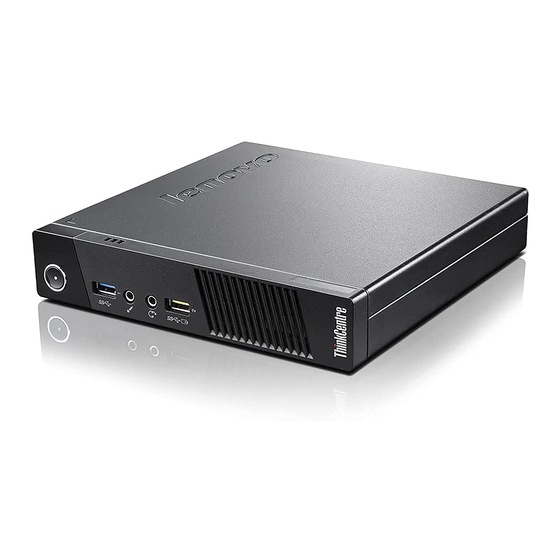
Figure 15 “Front connector, control, and indicator locations” on page 86 shows the locations of the connectors, controls, and indicators on the front of your computer. Figure 15. Front connector, control, and indicator locations ThinkCentre M83 and M93/p Hardware Maintenance Manual... -
Page 95: Locating Connectors On The Rear Of Your Computer
Power button Bluetooth activity indicator Wireless activity indicator Hard disk drive activity indicator Power indicator USB 3.0 connector Microphone connector Headset connector (also known as combo audio jack) Always On USB 3.0 connector Notes: • Indicators , and are visible only when they are lit. •... -
Page 96: Locating Major Frus And Crus
If you connect a Lenovo-recommended USB 1.1 keyboard to this connector, you can power on the computer or wake it up from S4 hibernation mode by pressing Alt+P on the keyboard. Ensure that you use a Lenovo-recommended keyboard that supports the smart power on feature. - Page 97 Figure 17. Component locations The following table lists the major FRUs shown in Figure 17 “Component locations” on page 89 and identifies which FRUs also are self-service CRUs or optional-service CRUs. Notes: Chapter 7 Locations...
-
Page 98: Looking Up Fru Information
For detailed FRU information, such as the FRU part numbers and supported computer models, go to: http:/www.lenovo.com/serviceparts-lookup Locating parts on the system board Note: Your computer comes with one of the following system boards. ThinkCentre M83 and M93/p Hardware Maintenance Manual... - Page 99 Figure 18 “System board part locations” on page 91 shows the locations of the parts on the system board. Figure 18. System board part locations Serial (COM1) connector Power switch board cable connector Optional DisplayPort connector Memory slots (2) System fan connector Battery Microprocessor Mini PCI Express card slot...
- Page 100 ThinkCentre M83 and M93/p Hardware Maintenance Manual...
-
Page 101: Chapter 8. Replacing Frus (Machine Types: 10A0, 10A1, 10A6, 10A7, 10Ag, 10Ak, 10Al, And 10Be)
67 and “Locating connectors on the rear of your computer” on page 67. 4. Remove any screws that secure the computer cover. 5. Press the cover-release button on the side of the computer and slide the cover to the rear of the computer to remove the cover. © Copyright Lenovo 2013, 2014... -
Page 102: Removing And Reinstalling The Front Bezel
1. Remove all media from the drives and turn off all attached devices and the computer. Then, disconnect all power cords from electrical outlets and disconnect all cables that are connected to the computer. 2. Remove the computer cover. See “Removing the computer cover” on page 93. ThinkCentre M83 and M93/p Hardware Maintenance Manual... -
Page 103: Installing Or Replacing A Pci Card
3. Remove the front bezel by releasing the three plastic tabs on the left side and pivoting the front bezel outward. Figure 20. Removing the front bezel 4. To reinstall the front bezel, align the three plastic tabs on the right side of the front bezel with the corresponding holes in the chassis. - Page 104 3. At the rear of the computer, press the release button to open the card latch Figure 21. Opening the PCI card latch ThinkCentre M83 and M93/p Hardware Maintenance Manual...
- Page 105 4. Depending on whether you are installing or replacing a PCI card, do one of the following: • If you are installing a PCI card, remove the appropriate metal slot cover. • If you are replacing an old PCI card, grasp the old card that is currently installed and gently pull it out of the slot.
-
Page 106: Installing Or Replacing A Memory Module
The “X” mark indicates the memory slots into which the memory modules should be installed in different situations. The numbers 1, 2, 3, and 4 indicate the ThinkCentre M83 and M93/p Hardware Maintenance Manual... - Page 107 installation sequence. To locate the memory module slots, see “Locating parts on the system board” on page 72. UDIMM DIMM 1 DIMM 2 DIMM 3 DIMM 4 One UDIMM Two UDIMMs X, 1 X, 2 Three UDIMMs X, 3 X, 1 X, 2 Four UDIMMs X, 3...
-
Page 108: Replacing The Optical Drive
Attention: Do not open your computer or attempt any repair before reading and understanding the Chapter 1 “Safety information” on page 1. This section provides instructions on how to replace the optical drive. Note: The optical drive is available only in some models. ThinkCentre M83 and M93/p Hardware Maintenance Manual... - Page 109 To replace the optical drive, do the following: 1. Remove all media from the drives and turn off all attached devices and the computer. Then, disconnect all power cords from electrical outlets and disconnect all cables that are connected to the computer. 2.
-
Page 110: Installing Or Replacing The Card Reader
• To complete the installation or replacement, go to “Completing the parts replacement” on page 156. Installing or replacing the card reader This section provides instructions on how to replace the card reader. ThinkCentre M83 and M93/p Hardware Maintenance Manual... -
Page 111: Installing The Card Reader
Attention: Do not open your computer or attempt any repair before reading and understanding the Chapter 1 “Safety information” on page 1. Installing the card reader To install the card reader, do the following: 1. Remove all media from the drives and turn off all attached devices and the computer. Then, disconnect all power cords from electrical outlets and disconnect all cables that are connected to the computer. - Page 112 Figure 34. Removing the card reader cover 10. Reinstall the front bezel. See “Removing and reinstalling the front bezel” on page 94. ThinkCentre M83 and M93/p Hardware Maintenance Manual...
-
Page 113: Replacing The Card Reader
What to do next: • To work with another piece of hardware, go to the appropriate section. • To complete the installation or replacement, go to “Completing the parts replacement” on page 156. Replacing the card reader Attention: Do not open your computer or attempt any repair before reading and understanding the Chapter 1 “Safety information”... -
Page 114: Installing Or Replacing The Front Usb Assembly
2. Remove the computer cover. See “Removing the computer cover” on page 93. 3. Remove the front bezel. See “Removing and reinstalling the front bezel” on page 94. 4. Locate the card reader drive bay. See “Locating internal drives” on page 76. ThinkCentre M83 and M93/p Hardware Maintenance Manual... - Page 115 5. Carefully pivot the card reader retainer as shown to remove it from the chassis. Figure 38. Removing the card reader retainer 6. Install the card reader retainer on the side of the new front USB assembly. Figure 39. Installing the card reader retainer Chapter 8 Replacing FRUs (machine types: 10A0, 10A1, 10A6, 10A7, 10AG, 10AK, 10AL, and 10BE)
- Page 116 Figure 41. Removing the card reader cover 10. Reinstall the front bezel. See “Removing and reinstalling the front bezel” on page 94. ThinkCentre M83 and M93/p Hardware Maintenance Manual...
-
Page 117: Replacing The Front Usb Assembly
What to do next: • To work with another piece of hardware, go to the appropriate section. • To complete the installation or replacement, go to “Completing the parts replacement” on page 156. Replacing the front USB assembly Attention: Do not open your computer or attempt any repair before reading and understanding the Chapter 1 “Safety information”... -
Page 118: Replacing The Battery
Replacing the battery Attention: Do not open your computer or attempt any repair before reading and understanding the Chapter 1 “Safety information” on page 1. This section provides instructions on how to replace the battery. ThinkCentre M83 and M93/p Hardware Maintenance Manual... - Page 119 Your computer has a special type of memory that maintains the date, time, and settings for built-in features, such as parallel-port assignments (configuration). A battery keeps this information active when you turn off the computer. The battery normally requires no charging or maintenance throughout its life; however, no battery lasts forever.
-
Page 120: Replacing The Power Supply Assembly
3. Disconnect the power supply assembly cables from the system board and all drives. See “Locating parts on the system board” on page 72. 4. Release the power supply assembly cables from the cable clips and ties in the chassis. ThinkCentre M83 and M93/p Hardware Maintenance Manual... -
Page 121: Replacing The Heat Sink And Fan Assembly
9. Install and tighten the four screws to secure the power supply assembly. Note: Use only screws provided by Lenovo. 10. Reconnect the power supply assembly cables to the system board and each of the drives. - Page 122 • You might have to gently twist the heat sink and fan assembly to free it from the microprocessor. • Do not touch the thermal grease while handling the heat sink and fan assembly. ThinkCentre M83 and M93/p Hardware Maintenance Manual...
-
Page 123: Replacing The Microprocessor
8. Position the new heat sink and fan assembly on the system board so that the four screws are aligned with the holes on the system board. Note: Position the new heat sink and fan assembly so that the heat sink and fan assembly cable is toward the microprocessor fan connector on the system board. - Page 124 10. Note the orientation of the new microprocessor. Hold the new microprocessor by its edges and align the notches on it with the tabs in the microprocessor socket. Then, carefully lower the new microprocessor straight down into the microprocessor socket. ThinkCentre M83 and M93/p Hardware Maintenance Manual...
-
Page 125: Replacing The System Board
Note: The small triangle on one corner of the new microprocessor is the microprocessor orientation indicator. The new microprocessor is in the correct orientation when this indicator faces the beveled corner of the microprocessor socket. Figure 51. Installing the microprocessor 11. - Page 126 11. Install the new system board into the chassis by aligning the eight screw holes in the new system board with the corresponding mounting studs on the chassis. Then, install the eight screws to secure the system board by following the sequence shown in the following illustration. ThinkCentre M83 and M93/p Hardware Maintenance Manual...
- Page 127 Figure 53. Installing the eight screws to secure the system board 12. Install the heat sink and fan assembly and connect the heat sink and fan assembly cable to the new system board. See “Replacing the heat sink and fan assembly” on page 113. 13.
-
Page 128: Installing Or Replacing The Msata Solid-State Drive
Note: The mSATA solid-state drive is only available in some models. For new installation, see “Installing the mSATA solid-state drive” on page 120. For replacement, see “Replacing the mSATA solid-state drive” on page 122. Installing the mSATA solid-state drive To install the mSATA solid-state drive, do the following: ThinkCentre M83 and M93/p Hardware Maintenance Manual... - Page 129 1. Insert the mSATA solid-state drive into the mini PCI Express slot on the storage converter, and then press the mSATA solid-state drive downward. Figure 55. Installing the mSATA solid-state drive into the storage converter 2. Install the two screws to secure the mSATA solid-state drive to the storage converter. Figure 56.
-
Page 130: Replacing The Msata Solid-State Drive
3. Remove the front bezel. See “Removing and reinstalling the front bezel” on page 94. 4. Locate the card reader. See “Locating major FRUs and CRUs” on page 70. 5. Disconnect the signal cable and power cable from the mSATA solid-state drive. ThinkCentre M83 and M93/p Hardware Maintenance Manual... - Page 131 6. Press the blue retaining clip to remove the mSATA solid-state drive storage converter out of the chassis. Figure 58. Removing the mSATA solid-state drive storage converter 7. Remove the two screws that secure the mSATA solid-state drive from the storage converter. Figure 59.
- Page 132 9. To install a new mSATA solid-state drive, insert the mSATA solid-state drive into the mini PCI Express slot on the storage converter, and then press the mSATA solid-state drive downward. Figure 61. Installing the mSATA solid-state drive into the storage converter ThinkCentre M83 and M93/p Hardware Maintenance Manual...
- Page 133 10. Install the two screws to secure the mSATA solid-state drive to the storage converter. Figure 62. Installing the screws that secure the mSATA solid-state drive 11. Slide the mSATA solid-state drive storage converter into the card reader drive bay until it snaps into position.
-
Page 134: Replacing The Primary Hard Disk Drive
5. Pull the blue handle to release and remove the hard disk drive from the bracket. Figure 64. Removing the primary hard disk drive 6. Flex the sides of the blue bracket to remove the hard disk drive from the bracket. ThinkCentre M83 and M93/p Hardware Maintenance Manual... - Page 135 7. To install a new hard disk drive into the blue bracket, flex the bracket and align pin , pin , pin and pin on the bracket with the corresponding holes in the hard disk drive. Do not touch the circuit board on the bottom of the hard disk drive.
-
Page 136: Replacing The Secondary Hard Disk Drive
5. Pull the blue handle to release and remove the hard disk drive from the hard disk bracket. Figure 67. Removing the secondary hard disk drive 6. Flex the sides of the blue bracket to remove the hard disk drive from the bracket. ThinkCentre M83 and M93/p Hardware Maintenance Manual... - Page 137 7. To install a new hard disk drive into the blue bracket, flex the bracket and align pin , pin , pin and pin on the bracket with the corresponding holes in the hard disk drive. Do not touch the circuit board on the bottom of the hard disk drive.
-
Page 138: Installing The Solid-State Drive
1. Install the solid-state drive into the storage converter. Then, install the four screws to secure the solid-state drive to the storage converter. Figure 70. Installing the solid-state drive into the storage converter ThinkCentre M83 and M93/p Hardware Maintenance Manual... -
Page 139: Replacing The Front Fan Assembly
2. To install the solid-state drive with the storage converter into the 3.5-inch hard disk drive bracket, flex the bracket and align pin , pin , pin , and pin on the bracket with the corresponding holes in the storage converter. Figure 71. - Page 140 5. Remove the front bezel. See “Removing and reinstalling the front bezel” on page 94. 6. Install the new front fan assembly by aligning the new rubber mounts with the corresponding holes in the chassis and push the rubber mounts through the holes. ThinkCentre M83 and M93/p Hardware Maintenance Manual...
-
Page 141: Replacing The Rear Fan Assembly
7. Pull the tips of the rubber mounts until the front fan assembly is secured in place. Figure 73. Installing the front fan assembly 8. Connect the front fan assembly cable to the power fan connector on the system board. 9. - Page 142 Figure 74. Removing the rear fan assembly 6. Install the new rear fan assembly by aligning the new rubber mounts with the corresponding holes in the chassis and push the rubber mounts through the holes. ThinkCentre M83 and M93/p Hardware Maintenance Manual...
-
Page 143: Replacing The Front Audio And Usb Assembly
7. Pull on the tips of the rubber mounts until the rear fan assembly is secured in place. Figure 75. Installing the rear fan assembly 8. Connect the rear fan assembly cable to the system fan connector on the system board. What to do next: •... - Page 144 6. Remove the screw that secures the front audio and USB assembly. Then, remove the front audio and USB assembly from the chassis. Figure 76. Removing the front audio and USB assembly ThinkCentre M83 and M93/p Hardware Maintenance Manual...
- Page 145 7. Route the cables of the new front audio and USB assembly through the corresponding square hole in the front of the chassis. Then position the new front audio and USB assembly on the chassis as shown. Figure 77. Installing the front audio and USB assembly Chapter 8 Replacing FRUs (machine types: 10A0, 10A1, 10A6, 10A7, 10AG, 10AK, 10AL, and 10BE)
-
Page 146: Replacing The Internal Speaker
2. Remove the computer cover. See “Removing the computer cover” on page 93. 3. Locate the internal speaker connector on the system board. See “Locating parts on the system board” on page 72. 4. Disconnect the internal speaker cable from the system board. ThinkCentre M83 and M93/p Hardware Maintenance Manual... - Page 147 5. Push the metal tab on the right side of the internal speaker and slide the internal speaker toward the right to completely remove it from the chassis. Figure 79. Removing the old internal speaker Chapter 8 Replacing FRUs (machine types: 10A0, 10A1, 10A6, 10A7, 10AG, 10AK, 10AL, and 10BE)
-
Page 148: Replacing The Thermal Sensor
4. Locate the thermal sensor. See “Locating major FRUs and CRUs” on page 70. 5. Disconnect the thermal sensor cable from the thermal sensor connector on the system board. See “Locating parts on the system board” on page 72. ThinkCentre M83 and M93/p Hardware Maintenance Manual... - Page 149 6. From inside the chassis, pivot the upper retaining clip that secures the plastic holder of the thermal sensor downward and then push the clip outward to release the clip. Then disengage the plastic holder holding the thermal sensor from the chassis. Figure 81.
-
Page 150: Replacing The Cover Presence Switch
3. Locate the cover presence switch. See “Locating major FRUs and CRUs” on page 70. 4. Disconnect the cover presence switch cable from the cover presence switch connector on the system board. See “Locating parts on the system board” on page 72. ThinkCentre M83 and M93/p Hardware Maintenance Manual... - Page 151 5. Remove the screw that secures the cover presence switch and remove the cover presence switch from the chassis. Figure 83. Removing the cover presence switch Chapter 8 Replacing FRUs (machine types: 10A0, 10A1, 10A6, 10A7, 10AG, 10AK, 10AL, and 10BE)
-
Page 152: Replacing The Wi-Fi Units
Replacing the Wi-Fi units involves the following operations: • “Removing the Wi-Fi adapter card” on page 145 • “Removing the Wi-Fi card module” on page 147 • “Installing the Wi-Fi units” on page 149 ThinkCentre M83 and M93/p Hardware Maintenance Manual... -
Page 153: Removing The Wi-Fi Adapter Card
Removing the Wi-Fi adapter card To remove a Wi-Fi adapter card, do the following: 1. Remove all media from the drives and turn off all attached devices and the computer. Then, disconnect all power cords from electrical outlets and disconnect all cables that are connected to the computer. 2. - Page 154 4. At the rear of the computer, press the release button to open the PCI card latch Figure 86. Opening the PCI card latch ThinkCentre M83 and M93/p Hardware Maintenance Manual...
-
Page 155: Removing The Wi-Fi Card Module
5. Grasp the Wi-Fi adapter card that is currently installed and gently pull it out of the slot. Figure 87. Removing the Wi-Fi adapter card Note: The card fits tightly into the card slot. If necessary, alternate moving each side of the card a small amount until it is removed from the card slot. - Page 156 Figure 88. Removing the Wi-Fi antenna cables 2. Remove the two screws that secure the Wi-Fi card module to the Wi-Fi adapter card. Figure 89. Removing the screws that secure the Wi-Fi card module ThinkCentre M83 and M93/p Hardware Maintenance Manual...
-
Page 157: Installing The Wi-Fi Units
3. Pull the Wi-Fi card module out of the mini PCI Express slot to remove it from the Wi-Fi adapter card. Figure 90. Removing the Wi-Fi card module What to do next: • To work with another piece of hardware, go to the appropriate section. •... - Page 158 1. Insert the Wi-Fi card module into the mini PCI Express slot, and then install the two screws to secure the Wi-Fi card module to the Wi-Fi adapter card. Figure 91. Installing the Wi-Fi card module Figure 92. Installing the screws that secure the Wi-Fi card module ThinkCentre M83 and M93/p Hardware Maintenance Manual...
- Page 159 2. Connect the front antenna cable and rear antenna cable to the Wi-Fi card module. Figure 93. Installing the Wi-Fi antenna cables 3. Install the Wi-Fi adapter card into the PCI Express x1 slot on the system board. See “Locating parts on the system board”...
-
Page 160: Installing Or Removing The Rear Wi-Fi Antenna
What to do next: • To work with another piece of hardware, go to the appropriate section. • To complete the installation or replacement, go to “Completing the parts replacement” on page 156. ThinkCentre M83 and M93/p Hardware Maintenance Manual... -
Page 161: Removing The Rear Wi-Fi Antenna
Removing the rear Wi-Fi antenna To remove the rear Wi-Fi antenna, do the following: 1. Remove all media from the drives and turn off all attached devices and the computer. Then, disconnect all power cords from electrical outlets and disconnect all cables that are connected to the computer. 2. - Page 162 Figure 97. Peeling off the paper that protects the stickers 5. Stick the front antenna to the front panel as shown. Then insert the front antenna cable through the hole in the front panel. Figure 98. Installing the front Wi-Fi antenna ThinkCentre M83 and M93/p Hardware Maintenance Manual...
-
Page 163: Removing The Front Wi-Fi Antenna
6. Connect the front antenna cable to the Wi-Fi card module. What to do next: • To work with another piece of hardware, go to the appropriate section. • To complete the installation or replacement, go to “Completing the parts replacement” on page 156. Removing the front Wi-Fi antenna To remove the front Wi-Fi antenna, do the following: 1. -
Page 164: Completing The Parts Replacement
3. Make sure that the cables are routed correctly before reinstalling the computer cover. Keep cables clear of the hinges and sides of the computer chassis to avoid interference with reinstalling the computer cover. ThinkCentre M83 and M93/p Hardware Maintenance Manual... -
Page 165: Obtaining Device Drivers
7. To update your configuration, refer to Chapter 5 “Using the Setup Utility program” on page 55. Note: In most areas of the world, Lenovo requires the return of the defective Customer Replaceable Unit (CRU). Information about this will come with the CRU or will come a few days after the CRU arrives. - Page 166 ThinkCentre M83 and M93/p Hardware Maintenance Manual...
-
Page 167: Chapter 9. Replacing Frus (Machine Types: 10A2, 10A3, 10A8, 10A9, 10Ah, 10Aj, 10Am, And 10An)
1. Remove any media from the drives and turn off all attached devices and the computer. 2. Disconnect all power cords from electrical outlets. 3. Disconnect the power cord, Input/Output cables, and any other cables that are connected to the computer. © Copyright Lenovo 2013, 2014... -
Page 168: Removing And Reinstalling The Front Bezel
1. Remove all media from the drives and turn off all attached devices and the computer. Then, disconnect all power cords from electrical outlets and disconnect all cables that are connected to the computer. 2. Remove the computer cover. See “Removing the computer cover” on page 159. ThinkCentre M83 and M93/p Hardware Maintenance Manual... -
Page 169: Accessing The System Board Components And Drives
3. Release the three plastic tabs on the top of the front bezel and pivot the front bezel outward to remove it from the computer. Figure 103. Removing the front bezel 4. To reinstall the front bezel, align the three plastic tabs on the bottom of the front bezel with the corresponding holes in the chassis, and then pivot the front bezel inward until it snaps into position. -
Page 170: Installing Or Replacing A Pci Card
4. Rotate the PCI card retainer to the open position. Depending on whether you are installing or replacing a PCI card, do one of the following: • If you are installing a PCI card, remove the appropriate metal slot cover. ThinkCentre M83 and M93/p Hardware Maintenance Manual... - Page 171 • If you are replacing an old PCI card, grasp the old card that is currently installed and gently pull it out of the slot. Figure 106. Removing a PCI card Notes: a. The card fits tightly into the card slot. If necessary, alternate moving each side of the card a small and equal amount until the card is removed from the slot.
-
Page 172: Installing Or Replacing A Memory Module
DIMM 1 DIMM 2 DIMM 3 DIMM 4 One UDIMM Two UDIMMs X, 1 X, 2 Three UDIMMs X, 3 X, 1 X, 2 Four UDIMMs X, 3 X, 2 X, 4 X, 2 ThinkCentre M83 and M93/p Hardware Maintenance Manual... - Page 173 To install or replace a memory module, do the following: 1. Remove all media from the drives and turn off all attached devices and the computer. Then, disconnect all power cords from electrical outlets and disconnect all cables that are connected to the computer. 2.
-
Page 174: Replacing The Optical Drive
• To complete the installation or replacement, go to “Completing the parts replacement” on page 234. Replacing the optical drive Attention: Do not open your computer or attempt any repair before reading and understanding the Chapter 1 “Safety information” on page 1. ThinkCentre M83 and M93/p Hardware Maintenance Manual... - Page 175 This section provides instructions on how to replace the optical drive. To replace the optical drive, do the following: 1. Remove all media from the drives and turn off all attached devices and the computer. Then, disconnect all power cords from electrical outlets and disconnect all cables that are connected to the computer. 2.
- Page 176 Figure 113. Removing the optical drive 8. Remove the optical drive retainer from the side of the old optical drive and install it on the side of the new optical drive. Figure 114. Installing the optical drive retainer ThinkCentre M83 and M93/p Hardware Maintenance Manual...
-
Page 177: Installing Or Replacing The Card Reader Assembly
9. Slide the new optical drive into the drive bay until it snaps into position. Figure 115. Installing the optical drive 10. Connect the signal cable and the power cable to rear of the new optical drive. What to do next: •... - Page 178 Figure 117. Installing the card reader assembly ThinkCentre M83 and M93/p Hardware Maintenance Manual...
-
Page 179: Replacing The Card Reader Assembly
6. Install the screw to secure the card reader assembly to the chassis. Figure 118. Installing the screw to secure the card reader assembly 7. Connect the cable of the new card reader assembly to the front USB connector 1 on the system board. See “Locating parts on the system board”... - Page 180 5. Disconnect the card reader cable from the system board. 6. Remove the screw that secures the card reader assembly. Push the card reader assembly to the right and then remove it from the chassis. Figure 121. Removing the card reader assembly ThinkCentre M83 and M93/p Hardware Maintenance Manual...
- Page 181 7. Install the new card reader assembly into the card reader drive bay until it snaps into position. Then, push the new card reader assembly to the left until the screw hole in the metal bracket of the card reader assembly is aligned with the corresponding hole in the chassis. Figure 122.
-
Page 182: Installing Or Replacing The Front Usb Assembly
5. The package of the new front USB assembly contains a front USB board, a metal bracket, and two screws. Install the front USB board into the metal bracket and then install the two screws to secure the front USB board to the bracket. ThinkCentre M83 and M93/p Hardware Maintenance Manual... - Page 183 Figure 125. Assembling the front USB assembly 6. Install the new front USB assembly into the card reader drive bay until it snaps into position. Then, push the new front USB assembly to the left until the screw hole in the metal bracket of the front USB assembly is aligned with the corresponding hole in the chassis.
-
Page 184: Replacing The Front Usb Assembly
2. Remove the computer cover. See “Removing the computer cover” on page 159. 3. Remove the front bezel. See “Removing and reinstalling the front bezel” on page 160 ThinkCentre M83 and M93/p Hardware Maintenance Manual... - Page 185 4. Press the retaining clip in the direction as shown and pivot the drive bay assembly upward at the same time. Figure 129. Pivoting the drive bay assembly upward 5. Disconnect the front USB assembly cable from the system board. 6.
- Page 186 What to do next: • To work with another piece of hardware, go to the appropriate section. • To complete the installation or replacement, go to “Completing the parts replacement” on page 234. ThinkCentre M83 and M93/p Hardware Maintenance Manual...
-
Page 187: Replacing The Battery
Replacing the battery Attention: Do not open your computer or attempt any repair before reading and understanding the Chapter 1 “Safety information” on page 1. Your computer has a special type of memory that maintains the date, time, and settings for built-in features, such as parallel-port assignments (configuration). -
Page 188: Installing Or Replacing The Msata Solid-State Drive
Figure 135. Pivoting the drive bay assembly upward 5. Take the new mSATA solid-state drive and the storage converter out of its static-protective package. ThinkCentre M83 and M93/p Hardware Maintenance Manual... - Page 189 6. Carefully insert the mSATA solid-state drive into the mini PCI Express slot on the storage converter at an angle of about 20 degrees. Then, press the mSATA solid-state drive downward. Figure 136. Installing the mSATA solid-state drive into the storage converter 7.
-
Page 190: Replacing The Msata Solid-State Drive
2. Remove the computer cover. See “Removing the computer cover” on page 159. 3. Remove the front bezel. See “Removing and reinstalling the front bezel” on page 160 ThinkCentre M83 and M93/p Hardware Maintenance Manual... - Page 191 4. Press the retaining clip in the direction as shown and pivot the drive bay assembly upward at the same time. Figure 139. Pivoting the drive bay assembly upward 5. Disconnect the signal cable and power cable from the rear of the mSATA solid-state drive storage converter.
- Page 192 9. Carefully insert the mSATA solid-state drive into the mini PCI Express slot on the storage converter at an angle of about 20 degrees. Then, press the mSATA solid-state drive downward. Figure 143. Installing the mSATA solid-state drive into the storage converter ThinkCentre M83 and M93/p Hardware Maintenance Manual...
- Page 193 10. Install the two screws that came with the mSATA solid-state drive to secure the drive to the storage converter. Figure 144. Installing the screws to secure the mSATA solid-state drive 11. Install the new mSATA solid-state drive into the card reader drive bay until it snaps into position. Then, push the new mSATA solid-state drive to the left until the screw hole in the metal bracket of the mSATA solid-state drive is aligned with the corresponding hole in the chassis.
-
Page 194: Replacing The Power Supply Assembly
2. Remove the computer cover. See “Removing the computer cover” on page 159. 3. Remove the front bezel. See “Removing and reinstalling the front bezel” on page 160 ThinkCentre M83 and M93/p Hardware Maintenance Manual... - Page 195 4. Gently pivot the two plastic retaining clips that secure the heat sink fan duct outward, and then lift the heat sink fan duct out of the chassis. Figure 146. Removing the heat sink fan duct 5. Press the retaining clip in the direction as shown and pivot the drive bay assembly upward at the same time.
- Page 196 Then, install the three screws to secure the new power supply assembly. Note: Use only screws provided by Lenovo. Figure 149. Installing the power supply assembly ThinkCentre M83 and M93/p Hardware Maintenance Manual...
-
Page 197: Replacing The Power Switch Unit
11. Connect the new power supply assembly cables to all drives and the system board. See “Locating parts on the system board” on page 82. What to do next: • To work with another piece of hardware, go to the appropriate section. •... - Page 198 82. 9. Reinstall the front bezel. See “Removing and reinstalling the front bezel” on page 160. What to do next: • To work with another piece of hardware, go to the appropriate section. ThinkCentre M83 and M93/p Hardware Maintenance Manual...
-
Page 199: Replacing The Heat Sink And Fan Assembly
• To complete the installation or replacement, go to “Completing the parts replacement” on page 234. Replacing the heat sink and fan assembly Attention: Do not open your computer or attempt any repair before reading and understanding the Chapter 1 “Safety information” on page 1. This section provides instructions on how to replace the heat sink and fan assembly. - Page 200 Partially tighten the screw , then fully tighten the screw , then fully tighten the screw b. Partially tighten the screw , then fully tighten the screw , then fully tighten the screw ThinkCentre M83 and M93/p Hardware Maintenance Manual...
- Page 201 Figure 155. Removing the heat sink and fan assembly 11. Connect the cable of the new heat sink and fan assembly to the microprocessor fan connector on the system board. See “Locating parts on the system board” on page 82. 12.
-
Page 202: Replacing The Microprocessor
6. Record the cable routing and connections. Then, locate the system board and disconnect all cables connected to the system board. See “Locating parts on the system board” on page 82. ThinkCentre M83 and M93/p Hardware Maintenance Manual... - Page 203 7. Lift the small handle and open the retainer to access the microprocessor Figure 158. Accessing the microprocessor 8. Carefully lift the microprocessor straight up and out of the microprocessor socket. Figure 159. Removing the microprocessor Notes: • Your microprocessor and socket might look different from the one illustrated. •...
-
Page 204: Replacing The System Board
This section provides instructions on how to replace the system board. CAUTION: The heat sink and microprocessor might be very hot. Before you open the computer cover, turn off the computer and wait several minutes until the computer is cool. ThinkCentre M83 and M93/p Hardware Maintenance Manual... - Page 205 To replace the system board, do the following: 1. Remove all media from the drives and turn off all attached devices and the computer. Then, disconnect all power cords from electrical outlets and disconnect all cables that are connected to the computer. 2.
- Page 206 11. Install the new system board into the chassis by aligning the eight screw holes in the new system board with the corresponding mounting studs on the chassis. Then, install the eight screws to secure the system board by following the sequence shown in the following illustration. ThinkCentre M83 and M93/p Hardware Maintenance Manual...
- Page 207 Figure 163. Installing the eight screws to secure the system board 12. Install the heat sink and fan assembly and connect the heat sink and fan assembly cable to the new system board. See “Replacing the heat sink and fan assembly” on page 191. 13.
-
Page 208: Replacing The Cover Presence Switch
3. Remove the front bezel. See “Removing and reinstalling the front bezel” on page 160 4. Locate the cover presence switch. See “Locating major FRUs and CRUs” on page 80. 5. Disconnect the cover presence switch cable from the cover presence switch connectors on the system board. ThinkCentre M83 and M93/p Hardware Maintenance Manual... - Page 209 6. Press the clip as shown and lift the cover presence switch up to remove it from the chassis. Figure 165. Removing the cover presence switch Chapter 9 Replacing FRUs (machine types: 10A2, 10A3, 10A8, 10A9, 10AH, 10AJ, 10AM, and 10AN)
-
Page 210: Replacing The Primary Hard Disk Drive
2. Remove the computer cover. See “Removing the computer cover” on page 159. 3. Remove the front bezel. See “Removing and reinstalling the front bezel” on page 160 ThinkCentre M83 and M93/p Hardware Maintenance Manual... - Page 211 4. Press the retaining clip in the direction as shown and pivot the drive bay assembly upward at the same time. Figure 167. Pivoting the drive bay assembly upward 5. Locate the primary hard disk drive. See “Locating major FRUs and CRUs” on page 80. 6.
-
Page 212: Installing Or Replacing The Secondary Hard Disk Drive
• To complete the installation or replacement, go to “Completing the parts replacement” on page 234. Installing or replacing the secondary hard disk drive This section provides instructions on how to install or replace the secondary hard disk drive. ThinkCentre M83 and M93/p Hardware Maintenance Manual... -
Page 213: Installing The Secondary Hard Disk Drive
Note: The secondary hard disk drive is only available in some models. Installing the secondary hard disk drive Attention: Do not open your computer or attempt any repair before reading and understanding the Chapter 1 “Safety information” on page 1. To install the secondary hard disk drive, do the following: 1. - Page 214 Figure 173. Positioning the carrier onto the bottom of the primary hard disk drive bay ThinkCentre M83 and M93/p Hardware Maintenance Manual...
- Page 215 7. Slide the secondary hard disk drive carrier to the left of the chassis until it snaps into position and the screw hole in the carrier is aligned with the screw hole in the bay. Figure 174. Installing the secondary hard disk drive carrier 8.
-
Page 216: Replacing The Secondary Hard Disk Drive
• To complete the installation or replacement, go to “Completing the parts replacement” on page 234. Replacing the secondary hard disk drive Attention: Do not open your computer or attempt any repair before reading and understanding the Chapter 1 “Safety information” on page 1. ThinkCentre M83 and M93/p Hardware Maintenance Manual... - Page 217 This section provides instructions on how to replace the secondary hard disk drive. To replace the secondary hard disk drive, do the following: 1. Remove all media from the drives and turn off all attached devices and the computer. Then, disconnect all power cords from electrical outlets and disconnect all cables that are connected to the computer.
- Page 218 Do not touch the circuit board on the bottom of the hard disk drive. Figure 180. Installing the hard disk drive into the bracket ThinkCentre M83 and M93/p Hardware Maintenance Manual...
-
Page 219: Installing The Solid-State Drive
9. Slide the new secondary hard disk drive into the carrier until it snaps into position. Figure 181. Installing the secondary hard disk drive 10. Connect the signal cable and the power cable to the primary hard disk drive and the new secondary hard disk drive. - Page 220 What to do next: • To work with another piece of hardware, go to the appropriate section. • To complete the installation or replacement, go to “Completing the parts replacement” on page 234. ThinkCentre M83 and M93/p Hardware Maintenance Manual...
-
Page 221: Replacing The Front Fan Assembly
Replacing the front fan assembly Attention: Do not open your computer or attempt any repair before reading and understanding the Chapter 1 “Safety information” on page 1. This section provides instructions on how to replace the front fan assembly. To replace the front fan assembly, do the following: 1. - Page 222 Figure 186. Installing the front fan assembly 8. Connect the cable of the new front fan assembly to the power fan connector on the system board. See “Locating parts on the system board” on page 82. ThinkCentre M83 and M93/p Hardware Maintenance Manual...
-
Page 223: Replacing The Front Audio And Usb Assembly
What to do next: • To work with another piece of hardware, go to the appropriate section. • To complete the installation or replacement, go to “Completing the parts replacement” on page 234. Replacing the front audio and USB assembly Attention: Do not open your computer or attempt any repair before reading and understanding the Chapter 1 “Safety information”... - Page 224 USB connector 1 on the system board. See “Locating parts on the system board” on page 82. What to do next: • To work with another piece of hardware, go to the appropriate section. ThinkCentre M83 and M93/p Hardware Maintenance Manual...
-
Page 225: Replacing The Internal Speaker
• To complete the installation or replacement, go to “Completing the parts replacement” on page 234. Replacing the internal speaker Attention: Do not open your computer or attempt any repair before reading and understanding the Chapter 1 “Safety information” on page 1. This section provides instructions on how to replace the internal speaker. - Page 226 7. Align the new internal speaker with the four metal clips on the inner side of the front panel, and then slide the internal speaker to the left side of the chassis until it snaps into position. Figure 192. Installing the internal speaker ThinkCentre M83 and M93/p Hardware Maintenance Manual...
-
Page 227: Replacing The Thermal Sensor
8. Connect the cable of the new internal speaker to the internal speaker connector on the system board. See “Locating parts on the system board” on page 82. What to do next: • To work with another piece of hardware, go to the appropriate section. •... - Page 228 Then, disengage the plastic holder holding the thermal sensor from the chassis. Figure 194. Removing the thermal sensor 8. Pull the entire thermal sensor out of the chassis. ThinkCentre M83 and M93/p Hardware Maintenance Manual...
-
Page 229: Replacing The Wi-Fi Units
9. Insert the connector and cable of the new thermal sensor into the hole in the chassis. Then, align the two tabs on the plastic holder holding the thermal sensor with the two holes in the chassis, and push the plastic holder until it snaps into position. Figure 195. -
Page 230: Removing The Wi-Fi Adapter Card
Figure 196. Disconnecting the Bluetooth cable 4. Hold the Wi-Fi adapter card and disconnect the front and rear Wi-Fi antenna cables from the Wi-Fi card module. Figure 197. Removing the Wi-Fi antenna cables ThinkCentre M83 and M93/p Hardware Maintenance Manual... -
Page 231: Removing The Wi-Fi Card Module
5. Rotate the PCI card retainer to the open position. Grasp the Wi-Fi adapter card that is currently installed and gently pull it out of the slot. Note: The card fits tightly into the card slot. If necessary, alternate moving each side of the card a small amount until it is removed from the card slot. -
Page 232: Installing The Wi-Fi Units
• To work with another piece of hardware, go to the appropriate section. • To complete the installation or replacement, go to “Completing the parts replacement” on page 234. Installing the Wi-Fi units To install the Wi-Fi units, do the following: ThinkCentre M83 and M93/p Hardware Maintenance Manual... - Page 233 1. Carefully insert the Wi-Fi card module into the mini PCI Express slot at an angle of about 20 degrees. Ensure that the Wi-Fi card module is firmly inserted and then pivot the module downward. Figure 201. Installing the Wi-Fi card module 2.
- Page 234 5. If the installed Wi-Fi card module supports the Bluetooth function, use a Bluetooth cable to connect the Bluetooth connector on the Wi-Fi adapter card to the front USB connector 1 on the system board. See “Locating parts on the system board” on page 82. ThinkCentre M83 and M93/p Hardware Maintenance Manual...
-
Page 235: Installing Or Removing The Rear Wi-Fi Antenna
Figure 205. Connecting the Bluetooth cable What to do next: • To work with another piece of hardware, go to the appropriate section. • To complete the installation or replacement, go to “Completing the parts replacement” on page 234. Installing or removing the rear Wi-Fi antenna This section provides instructions on how to install or remove the rear Wi-Fi antenna. - Page 236 Wi-Fi antenna nut to secure the rear Wi-Fi antenna cable connector on the Wi-Fi adapter card. Figure 207. Installing the nut and washer to secure the rear Wi-Fi antenna cable connector ThinkCentre M83 and M93/p Hardware Maintenance Manual...
-
Page 237: Removing The Rear Wi-Fi Antenna
5. Install the rear Wi-Fi antenna to the rear Wi-Fi antenna cable connector. Then, adjust the angle of the rear Wi-Fi antenna to prevent accidental breakage of the antenna. Figure 208. Installing the rear Wi-Fi antenna 6. Connect the rear Wi-Fi antenna cable to the Wi-Fi card module. See “Replacing the Wi-Fi units” on page 221. -
Page 238: Installing Or Removing The Front Wi-Fi Antenna
This section provides instructions on how to install or remove the front Wi-Fi antenna. Installing the front Wi-Fi antenna Attention: Do not open your computer or attempt any repair before reading and understanding the Chapter 1 “Safety information” on page 1. ThinkCentre M83 and M93/p Hardware Maintenance Manual... - Page 239 To install the front Wi-Fi antenna, do the following: 1. Remove all media from the drives and turn off all attached devices and the computer. Then, disconnect all power cords from electrical outlets and disconnect all cables that are connected to the computer. 2.
-
Page 240: Removing The Rear Wi-Fi Antenna
2. Remove the computer cover. See “Removing the computer cover” on page 159. 3. Straighten the rear Wi-Fi antenna so that it can be more easily twisted. ThinkCentre M83 and M93/p Hardware Maintenance Manual... -
Page 241: Replacing The Keyboard Or Mouse
4. Hold the thicker end of the rear Wi-Fi antenna and unscrew the Wi-Fi antenna from the rear of the computer. Figure 214. Removing the rear Wi-Fi antenna 5. Remove the Wi-Fi adapter card. See “Removing the Wi-Fi card module” on page 223. 6. -
Page 242: Completing The Parts Replacement
2. Ensure that the cables are routed correctly before reinstalling the computer cover. Keep cables clear of the hinges and sides of the computer chassis to avoid interference with reinstalling the computer cover. ThinkCentre M83 and M93/p Hardware Maintenance Manual... - Page 243 3. Press the release tab on the right side of the drive bay assembly and pivot the drive bay assembly downward until it snaps into position. Figure 217. Pivoting the drive bay assembly downward 4. Reinstall the front bezel. 5. Position the computer cover on the chassis so that the rail guides on the bottom of the computer cover engage the rails on the chassis.
-
Page 244: Obtaining Device Drivers
7. To update the configuration of your computer, refer to Chapter 5 “Using the Setup Utility program” on page 55. Note: In most areas of the world, Lenovo requires the return of the defective Customer Replaceable Unit (CRU). Information about this will come with the CRU or will come a few days after the CRU arrives. -
Page 245: Chapter 10. Replacing Frus (Machine Types: 10A4, 10A5, 10Aa, 10Ab, 10Df, 10Dg, 10Dh, 10Dj, 10E8, 10E9, 10Ea, And 10Eb)
3. Disconnect the power cord, Input/Output cables, and any other cables that are connected to the computer. 4. Remove the screw that secures the computer cover. Figure 219. Removing the screw that secures the computer cover © Copyright Lenovo 2013, 2014... -
Page 246: Installing External Options
Installing or removing the ac power adapter Attention: Do not open your computer or attempt any repair before reading and understanding the Chapter 1 “Safety information” on page 1. ThinkCentre M83 and M93/p Hardware Maintenance Manual... - Page 247 This section provides instructions on how to install or remove the ac power adapter. To install the ac power adapter, connect the ac power adapter to the ac power adapter connector at the rear of your computer and a workable electrical outlet. Secure the power cord into the power adapter cable loop at the rear of the computer as shown.
-
Page 248: Installing Or Removing The Vertical Stand
® Note: The vertical stand and Video Electronics Standards Association (VESA ) mount bracket are optional parts. If your computer comes with the VESA mount bracket installed, ensure that you remove the VESA ThinkCentre M83 and M93/p Hardware Maintenance Manual... - Page 249 mount bracket before you install the vertical stand. To remove the VESA mount bracket, see “Installing or removing the VESA mount bracket” on page 242. To install the vertical stand, do the following: 1. Turn off the computer. 2. Align the rear of the computer with the rear of the vertical stand and position the computer on the vertical stand as shown.
-
Page 250: Installing Or Removing The Vesa Mount Bracket
1. Remove all media from the drives and turn off all attached devices and the computer. Then, disconnect all power cords from electrical outlets and disconnect all cables that are connected to the computer. ThinkCentre M83 and M93/p Hardware Maintenance Manual... - Page 251 2. Slide the computer into the VESA mount bracket. Figure 225. Installing the VESA mount bracket 3. Install the two screws to secure the VESA mount bracket to the computer. Figure 226. Installing the screws to secure the VESA mount bracket To remove the VESA mount bracket, do the following: 1.
-
Page 252: Installing Or Removing The Ac Power Adapter Bracket
This section provides instructions on how to install or remove the ac power adapter bracket. Note: The ac power adapter bracket is only available on some models. To remove the ac power adapter bracket, do the following: ThinkCentre M83 and M93/p Hardware Maintenance Manual... - Page 253 1. Remove all media from the drives and turn off all attached devices and the computer. Then, disconnect all power cords from electrical outlets and disconnect all cables that are connected to the computer. 2. Pull the tab and then slide the ac power adapter bracket as shown to remove it from the VESA mount bracket.
-
Page 254: Replacing The Optical Drive
1. Remove all media from the drives and turn off all attached devices and the computer. Then, disconnect all power cords from electrical outlets and disconnect all cables that are connected to the computer. 2. Disconnect the optical drive cable from the USB connector on the computer. ThinkCentre M83 and M93/p Hardware Maintenance Manual... - Page 255 3. Remove the screw that secures the optical drive box on the VESA mount bracket and then slide the optical drive box as shown to remove it from the VESA mount bracket. Figure 231. Removing the optical drive box 4. Remove the screw that secures the optical drive in the optical drive box. Use a screwdriver to slide the optical drive forward and then remove the optical drive from the optical drive box.
- Page 256 6. Align the two screw holes in the optical drive metal plate with the corresponding holes in the new optical drive and then install the two screws to secure the metal plate on the new optical drive. Figure 234. Installing the optical drive metal plate ThinkCentre M83 and M93/p Hardware Maintenance Manual...
- Page 257 7. Slide the new optical drive into the optical drive box until it snaps into position. Figure 235. Installing the optical drive into the optical drive box 8. Install the screw that secures the optical drive in the optical drive box. Figure 236.
- Page 258 9. Align the two holes in the optical drive box with the two screws on the VESA mount bracket and then slide the optical drive box as shown to install it on the VESA mount bracket. Figure 237. Installing the optical drive box ThinkCentre M83 and M93/p Hardware Maintenance Manual...
-
Page 259: Installing Or Removing The Hard Disk Drive Assembly
10. Install the screw that secures the optical drive box on the VESA mount bracket. Figure 238. Installing the screw that secures the optical drive box 11. Connect the optical drive cable to a USB connector on the computer. See “Locating connectors on the rear of your computer”... - Page 260 Slide the hard disk drive assembly as shown until the two screw holes are aligned with the corresponding screw posts on the system board. Figure 240. Installing the hard disk drive assembly ThinkCentre M83 and M93/p Hardware Maintenance Manual...
-
Page 261: Replacing The Secondary Hard Disk Drive
2. Install the two screws to secure the hard disk drive assembly. Figure 241. Installing the screws to secure the hard disk drive assembly 3. Connect the signal cable and the power cable to the hard disk drive. What to do next: •... - Page 262 4. Slide the release button on the optical drive box and then remove the secondary hard disk drive adapter from the optical drive box. Figure 243. Removing the secondary hard disk drive adapter from the optical drive box ThinkCentre M83 and M93/p Hardware Maintenance Manual...
- Page 263 5. Flex the sides of the hard disk drive adapter bracket and then pivot the hard disk drive adapter to remove the adapter from the adapter bracket. Figure 244. Removing the hard disk drive adapter from the adapter bracket 6. To remove the hard disk drive from the adapter, lift the adapter retaining latch. Slide the hard disk drive towards the retaining latch and then lift the hard disk drive out of the adapter.
- Page 264 Figure 247. Installing the hard disk drive into the adapter 9. Position the adapter into the adapter bracket and then pivot the adapter downward until it snaps into position. Figure 248. Installing the hard disk drive adapter into the adapter bracket ThinkCentre M83 and M93/p Hardware Maintenance Manual...
- Page 265 10. Slide the hard disk drive adapter bracket into the optical drive box until it snaps into position. Figure 249. Installing the adapter bracket into the optical drive box Chapter 10 Replacing FRUs (machine types: 10A4, 10A5, 10AA, 10AB, 10DF, 10DG, 10DH, 10DJ, 10E8, 10E9, 10EA, and 10EB)
- Page 266 11. Align the two holes in the optical drive box with the two screws on the VESA mount bracket and then slide the optical drive box as shown to install it on the VESA mount bracket. Figure 250. Installing the optical drive box ThinkCentre M83 and M93/p Hardware Maintenance Manual...
-
Page 267: Installing Or Removing The I/O Box
12. Install the screw that secures the optical drive box on the VESA mount bracket. Figure 251. Installing the screw that secures the optical drive box 13. Connect the secondary hard disk drive cable to a USB connector on the computer. See “Locating connectors on the rear of your computer”... - Page 268 1. Remove all media from the drives and turn off all attached devices and the computer. Then, disconnect all power cords from electrical outlets and disconnect all cables that are connected to the computer. ThinkCentre M83 and M93/p Hardware Maintenance Manual...
- Page 269 2. Align the two holes in the I/O box with the two screws on the VESA mount bracket and then slide the I/O box as shown to install it on the VESA mount bracket. Figure 253. Installing the I/O box Chapter 10 Replacing FRUs (machine types: 10A4, 10A5, 10AA, 10AB, 10DF, 10DG, 10DH, 10DJ, 10E8, 10E9, 10EA, and 10EB)
-
Page 270: Installing Or Replacing A Memory Module
4. Remove the hard disk drive assembly to get access to the memory slots. See “Installing or removing the hard disk drive assembly” on page 251. 5. If you are replacing an old memory module, open the retaining clips and gently pull the memory module out of the memory slot. ThinkCentre M83 and M93/p Hardware Maintenance Manual... -
Page 271: Replacing The Battery
Figure 255. Removing the memory module 6. Insert the notched end of the new memory module into the slot . Press the memory module firmly and pivot the memory module until it snaps into place. Make sure that the memory module is secured in the slot and does not move easily. - Page 272 9. Turn on the computer and all attached devices. 10. Use the Setup Utility program to set the date, time, and any passwords. See Chapter 5 “Using the Setup Utility program” on page 55. ThinkCentre M83 and M93/p Hardware Maintenance Manual...
-
Page 273: Replacing The Power Switch Board
What to do next: • To work with another piece of hardware, go to the appropriate section. • To complete the installation or replacement, go to “Completing the parts replacement” on page 286. Replacing the power switch board Attention: Do not open your computer or attempt any repair before reading and understanding the Chapter 1 “Safety information”... -
Page 274: Replacing The Wi-Fi Card Module
1. Remove all media from the drives and turn off all attached devices and the computer. Then, disconnect all power cords from electrical outlets and disconnect all cables that are connected to the computer. ThinkCentre M83 and M93/p Hardware Maintenance Manual... - Page 275 2. Remove the computer cover. See “Removing the computer cover” on page 237. 3. Remove the hard disk drive assembly. See “Installing or removing the hard disk drive assembly” on page 251. 4. Locate the Wi-Fi card module in the computer. See “Locating major FRUs and CRUs” on page 88. 5.
-
Page 276: Installing Or Removing The Front Wi-Fi Antenna
5. Align the two small columns on the bottom of the front Wi-Fi antenna with the two holes on the hard disk drive bracket as shown. Then, stick the front Wi-Fi antenna onto the hard disk drive bracket. Figure 266. Sticking the front Wi-Fi antenna ThinkCentre M83 and M93/p Hardware Maintenance Manual... - Page 277 6. Route the front Wi-Fi antenna cable through the five hooks on the hard disk drive bracket as shown. Figure 267. Routing the front Wi-Fi antenna cable 7. Reinstall the hard disk drive assembly without connecting the signal cable and power cable. See “Installing or removing the hard disk drive assembly”...
-
Page 278: Installing Or Removing The Rear Wi-Fi Antenna
2. Install the rear Wi-Fi antenna to the rear Wi-Fi antenna cable connector attached on the rear of the computer. ThinkCentre M83 and M93/p Hardware Maintenance Manual... -
Page 279: Replacing The Internal Speaker
3. Adjust the angle of the rear antenna to lower the risk of breaking the antenna by accident. Figure 270. Installing the rear Wi-Fi antenna To remove the rear Wi-Fi antenna, do the following: 1. Remove all media from the drives and turn off all attached devices and the computer. Then, disconnect all power cords from electrical outlets and disconnect all cables that are connected to the computer. - Page 280 5. Disconnect the internal speaker cable from the system board. 6. Release the internal speaker cable from the retaining clip on the side of the thermal module bracket. Figure 272. Releasing the internal speaker cable ThinkCentre M83 and M93/p Hardware Maintenance Manual...
- Page 281 7. Press the tab that secures the internal speaker as shown and then lift the internal speaker out of the internal speaker holder. Figure 273. Removing the internal speaker 8. Press the tab as shown and insert the new internal speaker into the internal speaker holder until the new internal speaker snaps into position and is secured by the tab Figure 274.
-
Page 282: Replacing The Cover Presence Switch
2. Remove the computer cover. See “Removing the computer cover” on page 237. 3. Locate the cover presence switch in the computer. See “Locating major FRUs and CRUs” on page 88. 4. Disconnect the cover presence switch cable from the system board. ThinkCentre M83 and M93/p Hardware Maintenance Manual... - Page 283 5. Pull the cover presence switch to remove it from the heat sink bracket. Figure 276. Removing the cover presence switch 6. Attach the new cover presence switch to the thermal module. Figure 277. Installing the cover presence switch 7. Connect the cable of the new cover presence switch to the cover presence switch connector on the system board.
-
Page 284: Replacing The System Fan
2. Remove the computer cover. See “Removing the computer cover” on page 237. 3. Locate the system fan in the computer. See “Locating major FRUs and CRUs” on page 88. 4. Disconnect the system fan cable from the system board. ThinkCentre M83 and M93/p Hardware Maintenance Manual... - Page 285 5. Remove the three screws that secure the system fan to the thermal module, and then lift the system fan to remove it from the computer. Figure 278. Removing the system fan Chapter 10 Replacing FRUs (machine types: 10A4, 10A5, 10AA, 10AB, 10DF, 10DG, 10DH, 10DJ, 10E8, 10E9, 10EA, and 10EB)
-
Page 286: Replacing The Thermal Module
1. Remove all media from the drives and turn off all attached devices and the computer. Then, disconnect all power cords from electrical outlets and disconnect all cables that are connected to the computer. ThinkCentre M83 and M93/p Hardware Maintenance Manual... - Page 287 2. Remove the computer cover. See “Removing the computer cover” on page 237. 3. Locate the thermal module in the computer. See “Locating major FRUs and CRUs” on page 88. 4. Remove the internal speaker. See “Replacing the internal speaker” on page 271. 5.
-
Page 288: Replacing The Microprocessor
3. Remove the thermal module. See “Removing the computer cover” on page 237. Note: Place the thermal module on its back so that the thermal grease on the bottom of it does not get in contact with anything. ThinkCentre M83 and M93/p Hardware Maintenance Manual... - Page 289 4. Lift the small handle and open the retainer to access the microprocessor Figure 282. Accessing the microprocessor 5. Lift the microprocessor straight up and out of the microprocessor socket. Notes: • Your microprocessor and socket might look different from the one illustrated. •...
-
Page 290: Replacing The System Board
The thermal module and microprocessor might be very hot. Before you open the computer cover, turn off the computer and wait several minutes until the computer is cool. To replace the system board, do the following: ThinkCentre M83 and M93/p Hardware Maintenance Manual... - Page 291 1. Remove all media from the drives and turn off all attached devices and the computer. Then, disconnect all power cords from electrical outlets and disconnect all cables that are connected to the computer. 2. Remove the computer cover. See “Removing the computer cover” on page 237. 3.
- Page 292 Figure 287. Installing the five screws to secure the system board 13. Reinstall the thermal module. See “Replacing the thermal module” on page 278. ThinkCentre M83 and M93/p Hardware Maintenance Manual...
-
Page 293: Replacing The Keyboard Or Mouse
14. Reinstall the system fan. See “Replacing the system fan” on page 276. 15. Reinstall the Wi-Fi card module if you have removed it. See “Replacing the Wi-Fi card module” on page 266. 16. Install all memory modules removed from the failing system board onto the new system board. See “Installing or replacing a memory module”... -
Page 294: Completing The Parts Replacement
2. Before reinstalling the computer cover, ensure that the cables are routed correctly. Keep cables clear of the hinges and sides of the computer chassis to avoid interference with reinstalling the computer cover. ThinkCentre M83 and M93/p Hardware Maintenance Manual... - Page 295 3. Position the computer cover on the chassis and then push the cover to the rear of the computer until it snaps into position. Figure 290. Installing the computer cover Chapter 10 Replacing FRUs (machine types: 10A4, 10A5, 10AA, 10AB, 10DF, 10DG, 10DH, 10DJ, 10E8, 10E9, 10EA, and 10EB)
-
Page 296: Obtaining Device Drivers
6. To update your configuration, refer to Chapter 5 “Using the Setup Utility program” on page 55. Note: In most areas of the world, Lenovo requires the return of the defective Customer Replaceable Unit (CRU). Information about this will come with the CRU or will come a few days after the CRU arrives. -
Page 297: Chapter 11. Additional Service Information
– Start the Setup Utility. – Select Main menu. • Sources for obtaining the latest level BIOS available 1. Lenovo support web site: http://www.lenovo.com/support/ 2. Lenovo Customer Support Center 3. Levels 1 and 2 Support To update (flash) the BIOS, see “Flash update procedures” on page 289. -
Page 298: Updating (Flashing) The Bios From A Disc
Note: You can download a self-starting bootable disc image (known as an ISO image) with the system program updates to create a system-program-update disc. Go to http://www.lenovo.com/support. To update (flash) the BIOS from a disc on the Windows 8 (64-bit) or Windows 8.1 (64-bit) operating system, do the following: 1. -
Page 299: Updating (Flashing) The Bios From Your Operating System
Updating (flashing) the BIOS from your operating system Note: Because Lenovo makes constant improvements to its Web sites, the Web page contents are subject to change without notice, including the contents referenced in the following procedure. To update (flash) the BIOS from your operating system, do the following: 1. -
Page 300: Power Management
• For Windows 8.1: Click Choose what the power button does. 4. In the Shutdown setting section, clear Turn on fast startup. Note: If the settings are unavailable, click Change settings that are currently unavailable. 5. Click Save changes. ThinkCentre M83 and M93/p Hardware Maintenance Manual... -
Page 301: Appendix A. Notices
Lenovo representative for information on the products and services currently available in your area. Any reference to a Lenovo product, program, or service is not intended to state or imply that only that Lenovo product, program, or service may be used. Any functionally equivalent product, program, or service that does not infringe any Lenovo intellectual property right may be used instead. -
Page 302: Television Output Notice
Macrovision Corporation. Reverse engineering or disassembly is prohibited. European conformance CE mark Trademarks The following terms are trademarks of Lenovo in the United States, other countries, or both: Lenovo The Lenovo logo Rescue and Recovery... -
Page 303: Index
VESA mount bracket diagnostics, troubleshooting installing or replacing DisplayPort connector 69, 79, 88 secondary hard disk drive drivers, device 157, 236, 288 installing, replacing drives memory module bays 76, 85 internal speaker, replacing 138, 217, 271 © Copyright Lenovo 2013, 2014... - Page 304 73–74, 83–84, 91 power-on, password locating parts 73, 83, 91 primary hard disk drive, replacing locations 73–74, 83–84, 91 ThinkCentre M83 and M93/p Hardware Maintenance Manual...
- Page 305 VESA mount bracket, installing or removing VGA monitor connector 70, 80, 88 viewing and changing settings Wi-Fi card module, replacing Wi-Fi units, Wi-Fi adapter card, Wi-Fi card module, Wi-Fi antenna cable, replacing 144, 221 © Copyright Lenovo 2013, 2014...
- Page 306 ThinkCentre M83 and M93/p Hardware Maintenance Manual...