Table of Contents
Advertisement
Quick Links
3001391 01.07
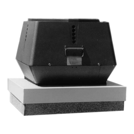
GSV 200-450 Grease Fan
Product Information
Mechanical Installation
Electrical Installation
Start Up and Configuration
Maintenance and Troubleshooting
CM
C
US
EXHAUSTO Inc.
1200 Northmeadow Pkwy.
Suite 180
Roswell, GA 30076
........................ Chapter 1 + 2
......................... Chapter 3
............................. Chapter 4
.................. Chapter 5
P: 770.587.3238
F: 770.587.4731
T: 800.255.2923
info@exhausto.com
us.exhausto.com
Installation & Operating Manual
USA
CAN
...... Chapter 6
Job Name:
Installer:
Installation Date:
Advertisement
Table of Contents

Related Manuals for Exhausto GSV 200-450


Summary of Contents for Exhausto GSV 200-450
- Page 1 Installation & Operating Manual 3001391 01.07 GSV 200-450 Grease Fan Product Information ......Chapter 1 + 2 Mechanical Installation ......Chapter 3 Electrical Installation ......Chapter 4 Start Up and Configuration ....Chapter 5 Maintenance and Troubleshooting ..Chapter 6...
-
Page 2: Symbol Legend
System design documentation is 3. Installation work and electrical wiring must be done by a available from any authorized EXHAUSTO representative. qualified person(s) in accordance with applicable codes and standards. Accessories, like roof curbs and variable frequency drives, 4. -
Page 3: Product Information
It is intended for use as a part of a restaurant kitchen exhaust system and grease applications according to NFPA 96.The use of the EXHAUSTO Grease Fan is not restricted to any type of chimney or grease duct. However, always follow the exhaust-hood manufacturer’s instructions regarding the venting. -
Page 4: Warranty
INSIDE the junction box. Please do not discard. 1.4 Warranty EXHAUSTO products are warranted for a period of two (2) years following the date of invoice. Replacement or repair will be at EXHAUSTO’s discretion, provided factory inspection shows a defect in material or workmanship. -
Page 5: Mechanical Installation
3001391 01.07 3. Mechanical Installation 3.1 Positioning In accordance with NFPA 96, roof mounted fans shall have their discharge outlet at least 40 inches above the roof surface. 3.2 Installation on Steel Duct • Insert the adapter (FR) into the grease duct, where the long collar engagement ensures safe anchoring (See Fig. -
Page 6: Electrical Requirements
Fig. 5 shows the wiring of the capacitor in the junction box. Fig. 4 Fig. 5 To fan Fan *) Junction box *) Repair switch To power Fan speed control *) *) supplied by EXHAUSTO Fig. 6 Variable Speed Fan Motor Fan Motor Capacitor LEGEND: 2-pole double- Factory Wired... - Page 7 3001391 01.07 4.3 Wiring Diagram for GSV 400-450 The connection diagram below shows how the fan is connected to the power source (see Fig. 7). Use a 3-conductor wire of min. 14 AWG with ground. Wiring must be run outside the duct, but can run between the duct and the roof curb.
- Page 8 3001391 01.07 4.4 Dual Voltage Motor Wiring GSV 400-450 can operate at either 3x208-230 VAC or 3x440-480 VAC (default). The motor wiring terminals in Fig. 8 show default Fig. 8 jumper positions for 3x440-480 VAC operation. If the application requires 3x208-230 VAC Fig.
-
Page 9: Start-Up And Configuration
Apply power and check that the impeller is rotating in the direction of the arrow on the side of the top motor cover. All EXHAUSTO fans run in a counterclockwise direction when viewed from the top. Double check if three phase motor is tested on temporary wiring. Switching any two leads will reverse the rotation. -
Page 10: Maintenance Intervals
Maintenance and Troubleshooting 6.1 Maintenance Intervals The EXHAUSTO Grease Fan is designed for prolonged use. For dirty or grease-laden exhaust, inspect the impeller after (3) months and set up a periodic inspection based on these findings. Clean as required. The fan motors are equipped with permanently lubricated sealed ball bearings. They require no lubrication. -
Page 11: Spare Parts Ordering
3001391 01.07 6.3 Spare Parts Ordering When ordering spare parts, please have the model number and part position number available White Motor Motor housing insulation Motor mounting plate Screw - SS (2) Screw - SS (2) Washer - SS (2) Washer - SS (2) Screw - SS Housing (top) - Page 12 3001391 01.07 GSV009, GSV012, GSV014, GSV016, GSV200, GSV250, GSV315, GSV400, GSV450 EN 60 335-1, EN 60 335-2-80, DS/EN ISO 12100-1, DS/EN ISO 12100-2 Machinery Directive: 98/37 9.13.01 EXHAUSTO Inc. P: 770.587.3238 1200 Northmeadow Pkwy. F: 770.587.4731 Suite 180 T: 800.255.2923 Roswell, GA 30076 info@exhausto.com...
Need help?
Do you have a question about the GSV 200-450 and is the answer not in the manual?
Questions and answers