
Related Manuals for Hitachi SK-HD1500-S2


Summary of Contents for Hitachi SK-HD1500-S2
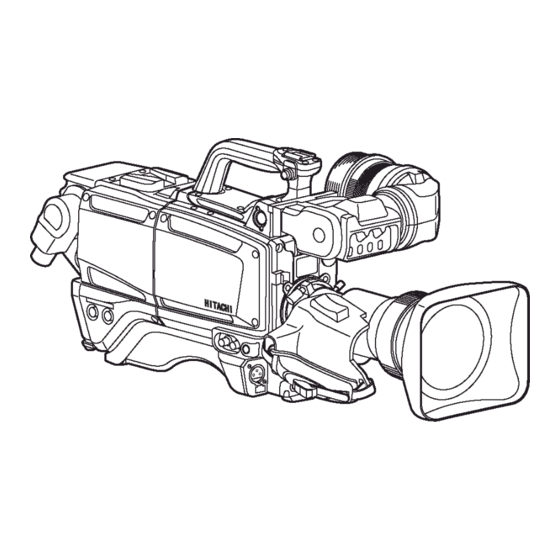
- Page 1 HD COLOR CAMERA SK-HD1500-S2 OPERATING INSTRUCTIONS Please read these operating instructions carefully for proper operation and keep them for future reference.
- Page 2 Note: The model and serial numbers of your product are important for you to keep for your convenience and protection. These numbers appear on the nameplate located on bottom of the product. Please record these numbers in the spaces provided below, and retain this manual for future reference.
-
Page 3: Safety Instructions
SAFETY INSTRUCTIONS Carefully read all safety messages in this manual and safety Instructions on your equipment. Follow recommended precautions and safe operating practices. SAFETY ALERT SYMBOL This is the “Safety Alert Symbol.” This symbol is used to call your attention to items or operations that could be dangerous to you or other persons using this equipment. -
Page 4: Important Safety Instructions
IMPORTANT SAFETY INSTRUCTIONS 1. Read Instructions All the safety and operating instructions should be read before the product is operated. 2. Retain Instructions The safety and operating instructions should be retained for future reference. 3. Heed Warnings All warnings on the product and the operating instructions should be adhered to. 4. - Page 5 14. Lightning For added protection for this product during a lightning storm, or when it is left unattended and unused for long periods of time, unplug it from the wall outlet. This will prevent damage to the product due to lightning and power-line surges. 15.
- Page 6 WICHTIGE SICHERHEITSANWEISUNGEN 1. Alle Anweisungen lesen. Vor Betrieb des Erzeugnisses sollten alle Sicherheits-und Bedienungsanleitungen gelesen werden. 2. Die Anweisungen aufbewahren. Die Sicherheits-und Bedienungsanleitungen sollten fünftigen Bezug aufbewahrt werden. 3. Warnungen beachten. Die Warnungen auf dem Erzeugnis und in den Bedienungsanleitungen solten beachtet werden. 4.
- Page 7 14. Blitzschlag Für zusätzlichen Schutz des Erzeugnisses während eines Gewitters oder bei Nichtverwendung für lange Zeit den Stecker aus der Steckdose ziehen. Dies verhütet Beschädigung durch Blitzschlag und Netzspannungsstöße. 15. Überlastung Wandsteckdosen, Verlängerungskabel und eingebaute Bequemlickkeitssteckdosen nicht überlasten, da dies Feuer oder elektrischen Schlag verursachen kann. 16.
- Page 8 MISES EN GARDE IMPORTANTES 1. Lire les instructions Lire toutes les instructions de sécurité et de fonctionnement avant de faire fonctionner l’appareil. 2. Conserver ces instructions Conserver les instructions de sécurité et de fonctionnement á des fins de référence ultérieure. 3.
- Page 9 14. Foudre Pour renforcer la protection de l’appareil pendant un orage, ou si l’on s’en éloigne ou qu’on reste longtemps sans l’utiliser, le débrancher de la source d’alimentation. Ceci permettra d’éviter tout dommage de l’appareil dú á la foudre et aux surtensions de ligne. 15.
- Page 10 Operation of this product in a residential area is likely to cause harmful interference in which case the user will be required to correct the interference at his own expense. WARNING Changes or modifications not expressly approved by Hitachi Kokusai Electric responsible for compliance could void the user’s authority to operate the equipment. For Canada This product does not exceed the class A/class B limits for radio noise emissions from digital apparatus as set out in the radio interference regulations.
-
Page 11: Table Of Contents
Contents Outline and features ..............................1 Warnings and cautions when using.........................3 Facility names and functions A..........................5 Lens installation..............................12 Lens flange back adjustment..........................13 White shading adjustment .............................14 Tripod mounting..............................17 5-inch viewfinder attachment..........................18 Viewfinder adjustment ............................19 Viewfinder indications............................21 Filter selection ...............................22 White and black balance adjustment........................23 Electronic shutter setting ............................28 Setup card ................................30 Function menu...............................37... -
Page 12: Outline And Features
Outline and features The SK-HD1500 is Hitachi’s new Multi-standard Digital processing improves Image Highlight High-Speed (Slow Motion) camera. With its new Quality 2.3 million pixels 3-CCD, the SK-HD1500 provides Knee saturation and auto-knee three times high speed superior picture, and is The auto knee provides a wide dynamic range suitable for shooting live sports productions. - Page 13 Outline and features Extensive User-Friendly Studio system configurations Quick focus The SK-HD1500 can be constructed a fiber cable system with camera control unit Quick Focus automatically opens the iris then CU-HD1500. sets the video level with the electric shutter. The system can be used with remote control unit With resulting shallow depth of focus, the exact RU-1500.
-
Page 14: Warnings And Cautions When Using
In event of difficulty Extremely hot or cold locations (exceeding -10 Disconnect from power and contact the nearest to 45°C), such as in enclosed vehicles. Hitachi Kokusai Electric service agency. Subject to strong vibration. Humid or dusty locations. Salt spray or corrosive gases. - Page 15 Warnings and cautions when using Optical Fiber Camera Cable & Connector Handling This camera is using the optical fiber cable & connector which is required special technique for handling. 1. Cable Connector & Receptacle (1) FCF (Fiber Cable Female) (2) FCM (Fiber Cable Male) (3) FCFR (Female Receptacle) (4)FCMR (Male Receptacle) 2.
-
Page 16: Facility Names And Functions A
Facility names and functions A Accessory shoe Shoulder belt hook A small spotlight can be attached without the Attachment for separately sold shoulder belt. light striking lens, viewfinder microphone. CALL button A RET button and an INCOM TALK button Press to call the CCU. can be mounted instead of the accessory shoe. - Page 17 Facility names and functions B Shoulder belt hook CCU connector Attachment for separately sold shoulder belt. Connector for fiber optic cable. Viewfinder connector AC230V OUT connector Connector for viewfinder cable. Maximum 100VA (AC230V) can be supplied to external unit. For detail, Refer to page 74. MON/RET output connector (BNC) HD-SDI signal output for monitor (75W).
- Page 18 Facility names and functions C MIC connector (XLR, 3pin) INCOM MIC on/off button Connector for microphone. Intercom microphone can be used while phantom power (DC+48V) can be pressing this button when switch E8 on camera supplied to front microphone from camera adaptor shown page 10 is set to “FRONT”.
- Page 19 Facility names and functions D POWER LED WHITE BAL switch Off: Camera power is off. PRE: The white balance is set to the memory On(Green): Camera power is on. value for 3200K. A or B: When the AUTO W/B BAL switch C4 is set to AWB, the white balance is adjusted FILTER button automatically.
- Page 20 Facility names and functions E CS switch RET1/2 transmission signal switch CS switch can be assigned as a shortcut by This switch is used to select a return video CUSTOM SW menu. signal among four external video sources input to CCU. These four signals can be assigned by CCU menu.
- Page 21 Facility names and functions E INCOM PGM 1/2 level INCOM 1/2 PD/ENG select switch Controls the receiving sound volume of the This switch is used to select the PD or ENG program. input of the external intercom system to be connected to the CCU rear side.
- Page 22 Facility names and functions F DC IN connector (XLR 4 pin) MIC LINE/OFF/+48V switch This connector should be used when the LINE: For a line level signal source. camera is used in self-control mode. OFF: Not to supply a power. +48V: To supply a power of +48VDC MIC SEL switch HD-SDI 1 output connector (BNC)
-
Page 23: Lens Installation
Lens installation Lens installation Install according to the following procedure. 1. Raise the lens lever and remove the mount 3. Lower the lens lever to secure the lens. cap. 2. Align the lens center mark with the indent at 4. Engage the cable with the cable clamp and the upper part of the lens mount and install connect it to the lens connector. -
Page 24: Lens Flange Back Adjustment
Lens flange back adjustment Lens flange back adjustment When operating a zoom lens, if the focus is not precisely aligned at both the telephoto and wide angle extremes of the lens, the flange back (distance from the lens mounting plane to the focal plane) is adjusted. -
Page 25: White Shading Adjustment
White shading adjustment White shading adjustment White shading adjustment is recommended after replacing the lens. The adjustment relates to the camera vertical coloration. If the lens includes an extender, the shading can be optimized for both extender on and off modes. (Vertical coloration refers to an effect whereby the image of an overall white sheet of paper tends toward green at the top and magenta at the bottom, or vice versa.) Adjustment... - Page 26 White shading adjustment 6. Open the WHITE SHADING sub menu from MAINTENANCE menu. 7. Shift cursor to WHT SHADING. 8. Press the MENU SELECT button for about 1 second to adjust white shading. The viewfinder top and bottom cursors flash to indicate automatic white shading adjustment in progress. The cursors extinguish at the end of adjustment.
- Page 27 Camera adapter installation Camera adapter installation Attach the camera adapter. Installation 1. Align the adapter guide pin with the camera guide shoe. Press to insert the adapter. □ □ □ 2. Tighten screws 2 and 3 to secure the camera adapter. Tighten screws fully to prevent wobble between adapter and camera.
-
Page 28: Tripod Mounting
Tripod mounting Tripod mounting Use the accessory TA-Z3 tripod adapter to mount the camera on a tripod. 1. Securely attach the tripod adapter to the tripod. Shift the adapter screw position to obtain the best balance. The adapter can accept two types of screws. Use the screw hole that matches the tripod. -
Page 29: 5-Inch Viewfinder Attachment
5-inch viewfinder attachment 5-inch viewfinder attachment Use the separately sold AT-500 viewfinder adapter when installing the VF-HD500 5-inch viewfinder. Installation 1. Raise the lock lever of the AT-500 horizontally and remove the viewfinder mounting screw from the AT-500. Insert this screw in the bottom of the viewfinder. Insert the screw together with the viewfinder into the AT-500 and set the lock lever forward, then turn the lever clockwise to secure it. -
Page 30: Viewfinder Adjustment
Viewfinder adjustment Viewfinder installation 1. Turn the lock lever as indicated by the arrow to secure the viewfinder guide. 2. Turn the viewfinder lock lever fully counter-clockwise. 3. Align the 2 viewfinder guide pins with the camera guide holes and insert the viewfinder. 4. - Page 31 Viewfinder adjustment Visibility adjustment Screen adjustments The focus can be fine adjusted to individual Adjust the viewfinder screen with following controls. preference. Brightness: BRIGHT control 1. Adjust the camera focus. Contrast: CONTR control 2. Turn the visibility ring to adjust the focus Peaking: PEAKING control of the viewfinder image.
-
Page 32: Viewfinder Indications
Viewfinder indications LED display in the View Finder (2 inch) R TALLY: Lights on during Red tally is on. G TALLY: Lights on during Green tally is on. EXT: Lights on during lens extender is used. MODE: Lights on during Gain is set to M or H, or shutter is on. Menu &... -
Page 33: Filter Selection
Filter selection Filter setting In order to obtain correct white balance, the sufficient optical filter selection is required accordance with the scene lighting source. The correct optical filter according to the scene light source needs to be selected in order to obtain correct white balance. Operation method Set the ND Filter knob as follows. -
Page 34: White And Black Balance Adjustment
White and black balance adjustment White balance adjustment White balance will be adjusted to the best effort in the sequence of AWB (auto white balance), ABB (auto black balance), and again AWB. Readjustment is normally not required even at power off/on. Be sure to adjust the white balance after changes in the lighting conditions. - Page 35 White and black balance adjustment Auto white balance error messages When auto white balance adjustment fails, the following error messages will be displayed on the viewfinder screen for about 6 seconds. Message Cause Correction The OUTPUT/AUTO Set the OUTPUT/AUTO KNEE switch to AUTO WHITE:NG KNEE switch is set to CAM.
-
Page 36: Black Balance Adjustment
White and black balance adjustment Black balance adjustment Black balance requires adjustment in the following situations. Equipment being used for the first time Equipment idle for an extended period Large change of ambient temperature Gamma setting changed 1. Set the AUTO W/B BAL switch to ABB for automatic black balance adjustment. A U T O W / B B A L sw i t ch 2. - Page 37 White and black balance adjustment Auto black balance error messages When auto black balance adjustment fails, the following error messages appear on the viewfinder screen for about 6 seconds. Message Cause Correction The OUTPUT/AUTO KNEE Set the OUTPUT/AUTO KNEE switch to AUTO BLACK:NG switch is set to BAR.
- Page 38 White and black balance adjustment Gray scale auto set up BLAK, GAIN, FLARE and GAMMA parameter can be adjusted automatically using with the gray scale chart. (Refer to the Function menu 4. MAINTENANCE) Gray scale chart with gate marker in the View Finder. Gate marker Gray scale auto set up can be accessed from Function menu or the Remote control unit and following message is displayed in the view finder during auto set up working...
-
Page 39: Electronic Shutter Setting
Electronic shutter setting Shutter modes The selectable electronic shutter modes and speeds are as follows. Mode Shutter speeds (second) Applications PRESET 1/250, 1/500, 1/1000, and 1/2000 Clear images of quickly moving objects. VARIABLE 1/179.8 to 1/2022 (179.82i) When shooting the computer monitor, It’s (LOCK SCAN) 1/150.0 to 1/2008 (150i) image scroll. - Page 40 Electronic shutter setting LOCK SCAN mode The lock scan mode avoids flicker in scenes showing a computer monitor screen. 1. Set the Shutter switch to SEL to produce the lock scan mode. 2. Push MENU BUTTON, top menu screen is displayed. The cursor can be changed by rotating MENU SEL KNOB.
-
Page 41: Setup Card
Setup card Setup card A SD memory card can be used for storing the setting menu data. The data can then be used to quickly set the proper setup. Setting data in a SD memory card can be transferred between same model, can not be transferred Between different ones. - Page 42 Setup card Setup card operation The SD memory card setting data is loaded and saved, and the setup card is formatted according to the SETUP CARD menu. If the insertion of the setup card is followed by indication of SETUP CARD menu, the setup card is checked.
- Page 43 Setup card If the setting data for this camera exists in the setup card, the date and time when the setting data was saved appear in the DATE and TIME fields. "-" appears where no corresponding file exists. If the checking revealed an error, the indication below appears, inhibiting all operations other than formatting.
- Page 44 Setup card Data load, save or clear 1. After Display the SETUP CARD menu, select a file to load, save or clear. Viewfinder displays in control head mode. CCU side monitor displays in system operation mode.
- Page 45 Setup card 2. Press > button 1 SEC and load, save or clear data from selected file. 3. The load, save or clear results appear.
- Page 46 Setup card Status pass & display for each camera operation 1. Camera system menu operation (display in the viewfinder) ■SETUP CARD MENU NOT FORMATTED No format FORMAT:PUSH > 1SEC Format OK ■SETUP CARD MENU ■SELECT FILE:< FILE DATE TIME FILE NAME: [VF]1 --/--/-- --:-- [VF]1 --/--/-- --:-- CARD OK [VF]2 --/--/-- --:-- & [VF]3 --/--/-- --:-- Formatted Select file CHECKING CARD......
- Page 47 Remove card NO CARD In event of error If setting data save or load, or setup card format results are erroneous, the setup card may be faulty. Change the setup card. If the error recurs, consult a Hitachi technical service representative.
-
Page 48: Function Menu
Function menu There are three function menu setting methods in the camera system chain which are, 1) Setup control unit SU-1000 FUNCTION button and MENU button on LCD. 2) Remote control unit RU-1500 FUNCTION button and MENU button on LCD. 3) Camera head MENU button. - Page 49 Function menu Main Menu:(Typical main menu) There are two kind cursor The cursor is moved up & down by the rotate knob and the cursor is changed parameter by the MENU SEL knob. The marker indicate sub menu hidden in behind. Main menu is categorized for each camera operation and grouping to each control items as possible which individual item has marker on right side of it...
- Page 50 Function menu The camera head is connected with a CCU and a RU as an operational camera system, the camera head View finder display TOP MENU as followings. This is mainly used for camera man’s operation. VF MENU Open this menu by pushing the MENU SW in side of the camera.
-
Page 51: Main Menu
Function menu 1. VF menu structure which are displayed in the viewfinder.) MAIN MENU SUB MENU ■VF MENU ■VF DETAIL :< ■MARKER1 SEL:<USER 1 VF OUT SEL :COLOR VF DETAIL :ON CENTER MARK:ON VF DETAIL :> DTL LEVEL : 0 SAFETY MARK:ON VF MARKER :> CRISP : 0 SIDE 4:3 :OFF SIDE PANEL :> 13:9 :OFF VF DISPLAY :> 14:9 :OFF VF ZEBRA :> 15:9 :OFF FOCUS IND :> CROSS :OFF BOX1 :OFF BOX2 :OFF ■VF MARKER :< ■MARKER2 SEL:<USER 1... -
Page 52: Sub Menu
Function menu 2. COLOR menu structure MAIN MENU SUB MENU ■COLOR MENU SCENE 0 ■GAIN :< SCENE 0 GAIN :> R GAIN : 0 BLACK/FLARE:> G GAIN : 0 GAMMA :>> B GAIN : 0 KNEE/CLIP :>> MASKING :>>> INITIALIZE : ■BLACK/FLARE:< SCENE 0 R BLACK : 0 G BLACK : 0 B BLACK : 0 R FLARE : 0 G FLARE : 0 B FLARE : 0 FLARE :ON M.BLACK : 0 INITIALIZE : ■GAMMA 1:> SCENE 0 ■GAMMA 2:< SCENE 0 R GAMMA : 0 U.GAMMA TBL:1[90%] G GAMMA : 0 ULTRA GAMMA:OFF B GAMMA : 0 BLK STR LEV: 0 TOTAL GAMMA: 0 BLK STRETCH:OFF... - Page 53 Function menu 3. DETAIL menu structure *Typical picture for explaining of DTL functions *CH1/CH2 A.PHASE adjustment When selected CH1 or CH2 A.PHASE item, Skin tone DTL phase auto marker is displayed in the center of the picture. Move the camera shooting position where you want to set Skin tone DTL and push function key one second.
- Page 54 Function menu 4. MAINTENANCE menu structure...
- Page 55 Function menu 5. FILE menu structure MAIN MENU SUB MENU ■FILE MENU ■SCENE FILE MENU SCENE FILE :> SCENE FILE :SCENE 0 LENS FILE :> STORE FILE :SCENE 0 STORE ALL INITIALIZE : ■LENS FILE MENU LENS FILE :LENS 1 AUTO IRIS :> WHT SHADING:> REGI :> ■AUTO IRIS :< LENS FILE :LENS 1 IRIS SPEED : 0 OPEN LIMIT : 127 CLOSE LIMIT: -85 INITIALIZE : ■WHT SHADING:< ■H SHADING:< LENS FILE :LENS 1 LENS FILE :LENS 1 EXTENDER :OFF[×1] EXTENDER :OFF[×1] R H SAW : 0 WHT SHADING:PUSH > 1SEC G H SAW : 0 B H SAW : 0 H SHADING :> R H PARA : 0...
- Page 56 Function menu 7. Each menu item & description 7.1 VF menu Item Setting Initial Description setting VF OUT SEL COLOR COLOR Y,R,G,B VF DETAIL Change screen to VF DETAIL menu. - - VF MARKER Change screen to VF MARKER menu. -...
- Page 57 Function menu 7.1.2.1 MARKER1 SEL/ MARKER2 SEL menu Item Setting Initial Description setting CENTER MARK ON,OFF Center marker ON and OFF. SAFETY MARK ON,OFF Safety Maker ON and OFF. SIDE ON,OFF Side 4:3 marker ON and OFF 13:9 ON,OFF Side 13:9 Marker ON and OFF 14:9 ON,OFF Side 14:9 marker ON and OFF...
- Page 58 Function menu 7.1.2.3 BOX1 SET/BOX2 SET menu Item Setting Initial Description setting H POSITION 0 to 255 Adjust horizontal position. V POSITION 0 to 255 Adjust vertical position. H SIZE 0 to 255 Adjust H. size of the box. V SIZE 0 to 255 Adjust V size of the box.
- Page 59 Function menu 7.1.3 SIDE PANEL menu Item Setting Initial Description setting SIDE PANEL OFF, 4:3, 13:9, Only when DISP SIZE is 16:9, it is 14:9, 15:9 effective. CONTRAST 1 to 5 Set side panel contrast BRIGHT 1 to 5 Set side panel brightness 7.1.4 VF DISPLAY menu Item Setting...
- Page 60 Function menu 7.1.6 FOCUS IND menu Item Setting Initial Description setting INDICATOR ON,OFF Display the focus assist indicator in VF, ON and OFF MARKER ON,OFF Display the detect area marker for the focus assist in VF, ON and OFF PEAK HOLD ON,OFF Display a peak position of the indicator.
- Page 61 Function menu 7.2 COLOR menu Item Description GAIN Change screen to GAIN menu. BLACK/FLARE Change screen to BLACK/FLARE menu. GAMMA Change screen to GAMMA menu. KNEE/CLIP Change screen to KNEE/CLIP menu. MASKING Change screen to MASKING menu. 7.2.1 GAIN menu Item Setting Initial...
- Page 62 Function menu 7.2.3 GAMMA1 menu Item Setting Initial Description setting R GAMMA -128 to 127 Adjust Red Gamma G GAMMA -128 to 127 Adjust Green Gamma B GAMMA -128 to 127 Adjust Blue Gamma TOTAL GAMMA -128 to 127 Adjust Total Gamma Select gamma curve value from GAMMA TABLE 3.0 to 8.0...
- Page 63 Function menu 7.2.6 KNEE/CLIP2 menu Item Setting Initial Description setting KNEE SAT -128 to 127 Adjust Knee Saturation. (*) KNEE SAT Knee Saturation function ON And ON,OFF WHITE CLIP -128 to 127 Adjust White Clip level WHITE CLIP ON,OFF White Clip function ON and OFF INITIALIZE Press the MENU SEL buttons to -...
- Page 64 Function menu 7.2.8 MASKING2 menu Item Setting Initial Description setting LINEAR R-G -64 to +63 Adjust liner matrix R-G parameter offset LINEAR R-B -64 to +63 Adjust liner matrix R-B parameter offset LINEAR G-R -64 to +63 Adjust liner matrix G-R parameter offset LINEAR G-B -64 to +63...
- Page 65 Function menu 7.3 DETAIL menu Item Description DETAIL Change screen to DETAIL menu. SKIN DTL Change screen to SKIN DTL menu. HIGH CHROMA Change screen to HIGH CHROMA menu. 7.3.1 DETAIL1 menu Item Setting Initial Description setting LEVEL -128 to +127 Adjust Detail level H GAIN -128 to +127...
- Page 66 Function menu 7.3.3 SKIN DTL1 menu Item Setting Initial Description setting CH SELECT 1ch,2ch CH selection for skin tone detail CH1 A.PHASE Set CH1 skin tone detail phase *1 - - S.DTL LEVEL -128 to +127 -128 Adjust CH1 skin tone detail level PHASE -128 to +127 Set &...
- Page 67 Function menu 7.3.5 HIGH CHROMA menu Item Setting Initial Description etting Adjust detail level in high -128 to +127 chrominance Red portion in the scene. Adjust detail level in high -128 to +127 chrominance Green portion in the scene. Adjust detail level in high -128 to +127 chrominance Blue portion in the scene.
- Page 68 Function menu 7.4 MAINTENANCE menu Item Description AUTO SETUP Change screen to AUTO SETUP menu. WHT SHADING Change screen to WHT SHADING menu. AUTO IRIS Change screen to AUTO IRIS menu. MIC GAIN Change screen to MIC GAIN menu. GAIN SET Change screen to GAIN SET menu.
- Page 69 Function menu 7.4.2 WHT SHADING menu Item Setting Initial Description setting LENS FILE LENS 1 to 8 LENS 1 White shading data can be stored to lens file. EXTENDER Display Lens extender position - - OFF(X1):Either of the following. ・When the extender is X1. ・The lens cable is not connected.
- Page 70 Function menu 7.4.5 AUTO IRIS menu Item Setting Initial Description setting AUTO IRIS REMOTE, AUTO Setting of Iris control mode. *1 AUTO IRIS TRIM -128 to +127 Adjust Auto iris output level PEAK/AVE 0/10, 1/9, 2/8, 0/10 Setting of Peak & Average detect for Auto iris 3/7, 4/6, 5/5 IRIS GATE...
-
Page 71: Shutter Menu
Function menu 7.4.7 GAIN SET menu Item Setting Initial Description setting M.GAIN LOW -3, 0 dB Low gain setting of M.Gain M.GAIN MID 0, 3, 6, 9, 12, MID gain setting of M.Gain 15, 18, 21dB M.GAIN HIGH 3, 6, 9, 12, 15, 12dB HIGH gain setting of M.Gain 18, 24dB... - Page 72 Function menu 7.4.10 SYSTEM menu Item Setting Initial Description setting CAMERA ID 1 to 99 Setting of camera number FAN MODE OFF,AUTO,LOW,HIGH AUTO Setting of FAN mode GL H PHASE -512 -512 Adjustment of GL Phase SDI AUDIO ON, OFF Embedded Audio ON and BAR TONE OFF, ON...
- Page 73 Function menu 7.5 FILE menu Item Setting Initial Description setting SCENE FILE Change screen to SCENE FILE menu. - - LENS FILE Change screen to LENS FILE menu. - - 7.5.1 SCENE FILE menu Item Setting Initial Description setting FILE SELECT SCENE 0 to SCENE 0 Selection of scene file setting 8, PRESET...
-
Page 74: File Structure
Function menu File structure There are ADJUST, COMMON, SCENE and LENS four major data files in the camera head memory. 1. The SCENE FILE is indicated at top right corner in the each menu in the FUNCTION menu. 2. The COMMON FILE and the TEMPORARY SCENE FILE data values are stored to the memory automatically. - Page 75 Function menu 7.6 CUSTOM SW menu Item Setting Initial Description setting CS-1 SW ZEBRA, ZEBRA Set CS-1 switch MARKER, VF-DTL, QUICK FOCUS(*), CA-CS SW ------, ------ Set CS switch in the VF-DTL, MARKER1, MARKER2 LENS VTR SW RET-2, TALK TALK Set VTR switch in the Lens.
- Page 76 Type of Auto setup & control items Following Auto setup functions are available at camera head and also remotely controlled from the RU-1500. Type of Auto Setup GRAY WHITE SKIN TONE AUTO AUTO SCALE SHADING DTL PHASE BLACK WHITE AUTO (*1) AUTO (*2)
- Page 77 Function menu Versatility and creativity function for HDTV picture quality Camera Alignment Goal should be: - Accurate reproduction of scene - Matching a previous set up - Developing your own unique “look” or a number of different look, depending on the situation May be required a different look to a newscast or dram series.
-
Page 78: Specifications
Specifications Camera Head SK-HD1500-S2 2/3-inch, IT-CCD Total pixels 2,010 (H) × 1,120(V) 2.3 million pixels Effective pixels 1,920 (H) × 1,080 (V) Native Scan 1080/179.82i, 1080/150i Prism F1.4 1X motorized filter wheel w/ 5 filter positions Optical Filter C: Cap, 1: CLEAR, 2: 1/4 ND, 3: 1/16 ND, 4: 1/64 ND... - Page 79 Specifications Camera Adaptor CA-HF1500 1X HFOC femail connector (LEMO/Tajimi Type) CCU connector SMPTE304M-type Fiber adaptor I-O 1X BNC HD-SDI1 (1080i) 1X BNC HD-SDI2 HD-SDI(1080i) RET.B OUT switch-able HD-SDI(1080i) 1X BNC PROMPT switch-able GENLOCK (analog Tri-level in or SD VBS OUT) 4-pin Script +12VDC OUT(1.0A max) 29-pin D-SUB for studio-adaptor 5-pin AC230V for Prompter Power / Tally out...
- Page 80 Specifications Dimensions ・SK-HD1500 / CA-HF1500 163 262 133 358 ・VF- 402...
- Page 81 Specifications ・VF-L90HD ・VF-HD500...
-
Page 82: Studio System Operation
Studio system operation Connection with system The SK-HD1500 can be constructed a fiber cable system. The CU-HD1500 and the CA-HF1500 are dedicated for the three times high speed camera system. This system can be used with remote control unit RU-1500. Setup control unit SU-1000 can control up to 12 camera systems. Up to 128 camera systems can be controlled with SU-1000 under the conditions of use Ethernet operation. -
Page 83: Service Information
Service information Connector pin diagrams LENS connector REMOTE connector 12pin 4pin Signal +12V output SD input SD output SD GND Signal AUX SW DC IN connector CALL TRG ENF AUTO IRIS CONTROL +12V IRIS POSITION IRIS A/R Signal EXETEND ZOOM POS F POS / L TX L RX +12V IN... - Page 84 Service information INTERCOM1/2 connector RET CONT 5 pin XLR female:HA16PRH-5S 6 pin female:HR10A-7R-6SB(74) Mating connector:HR10A-7P-6P Signal Signal INCOM 1 TALK ON/OFF MIC IN (C) INCOM 2 TALK ON/OFF MIC IN (H) RECEIVE(C) RECEIVE(H) RET 1 CTL RECEIVE(H) RET 2 CTL SCRIPT AC230V OUT 5 pin female:HR10A-7R-5SB(73)
-
Page 85: Application Note: Connecting Prompter Power
The prompter power connector is located behind the fibre connector on the Camera Adaptor CA-HF1500. This is a 5 pin socket with Power interlock. How to connect: Parts: 5 pin plug RM12BPE-5PH Hitachi code JMR0222 Connect as follows: Pin 1 230V AC... -
Page 86: Application Note: Intercom Setting For Carbon Type
Application note: Intercom setting for carbon type 1. Intercom setting for carbon type headset A standard setting is a dynamic type headset. Change a switch setup of a camera adaptor and a camera control unit at the time of carbon type headset use. - Page 87 Application note: Intercom setting for carbon type 2.Setting procedure 2.1 Loosen four screws of a left side panel, and a 2.3 Set up the switch in a unit according to the side panel is removed. headset to be used. INCOM1 : SW101 INCOM2 : SW102 screw 4 pcs...
-
Page 88: Application Note: Trunk Video Transmission
Application note: Trunk video transmission Summary: An external HD-SDI (1080i) video source can be transmitted from camera to CCU. The video source can be transmitted to CCU and then output from CCU in synchronization with SK-HD1500. How to use: Change an internal coaxial cable inside CA-HF1500 to assign the trunk video input on HD-SDI2 connector.
Need help?
Do you have a question about the SK-HD1500-S2 and is the answer not in the manual?
Questions and answers