Table of Contents
Advertisement
5/2-DAY PROGRAMMABLE THERMOSTAT
(FOR BOTH CONVENTIONAL AND HEAT PUMP SYSTEMS)
INSTALLATION AND OPERATING INSTRUCTIONS
• Please read all of these instructions carefully before beginning
installation.
• Label every wire terminal designation on your existing
thermostat wiring before removing your old thermostat.
• Ignore the color of the wires since they may not comply with
any standard. Please connect wires using the terminal letter
designations.
Thank you for your confidence in our product. To obtain the best results
from your investment, please read and follow the installation procedures
carefully, and one step at a time. This will save you time and minimize the
chance of damaging either the thermostat or possibly your heating and
cooling system. These instructions may contain information beyond that
which may be required for your particular installation.
SYSTEM COMPATIBILITY. . . . . . . . 2
FEATURES . . . . . . . . . . . . . . . . . 3
TOOLS YOU MAY NEED . . . . . . . . . 3
MOUNTING LOCATION . . . . . . . . . 4
REMOVE OLD THERMOSTAT . . . . . 4
INSTALL THERMOSTAT BASE . . . . . 5
WIRING INFORMATION . . . . . . . . . 5
CAUTIONS AND WARNINGS. . . . . . 6
WIRING DIAGRAMS . . . . . . . . . . . 8
HARDWARE SETUP OPTIONS . . . . 17
WARNING: Use Energizer
Energizer
DURACELL
© 2012 LUX PRODUCTS CORPORATION. ALL RIGHTS RESERVED
SMART TEMP
IMPORTANT!
®
®
is a registered trademark of Eveready Battery Company, Inc.
®
is a registered trademark of The Gillette Company, Inc.
P 5 2 1 U
®
UNIVERSAL
COMPLETE THE INSTALL . . . . . . . 19
FRONT PANEL ITEMS . . . . . . . . . 20
OPERATING INSTRUCTIONS. . . . . 21
TEMPERATURE PROGRAMS. . . . . 24
ADVANCED FEATURES . . . . . . . . 25
BATTERY REPLACEMENT. . . . . . . 32
TECHNICAL ASSISTANCE. . . . . . . 33
LIMITED WARRANTY . . . . . . . . . 33
MERCURY NOTICE . . . . . . . . . . . 33
or DURACELL
®
Alkaline Batteries Only.
52126
Advertisement
Table of Contents

Related Manuals for Lux Products LuxPro P521U


Summary of Contents for Lux Products LuxPro P521U
-
Page 1: Table Of Contents
P 5 2 1 U SMART TEMP ® UNIVERSAL 5/2-DAY PROGRAMMABLE THERMOSTAT (FOR BOTH CONVENTIONAL AND HEAT PUMP SYSTEMS) INSTALLATION AND OPERATING INSTRUCTIONS 52126 IMPORTANT! • Please read all of these instructions carefully before beginning installation. • Label every wire terminal designation on your existing thermostat wiring before removing your old thermostat. -
Page 2: System Compatibility
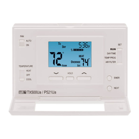
P521U LCD Display Screen Fan Mode Set Slide Switch Switch AUTO 5 : 36 ˚ DAY/TIME HEAT TEMP PROG ˚ AIR FILTER TEMPERATURE HEAT HOLD EMER COOL NEXT System Mode Switch UP, DOWN and HOLD Buttons SYSTEM COMPATIBILITY: The electrical rating for this thermostat is 1.5 Amps per terminal, with a maximum total combined load of 3.0A for all terminals combined. -
Page 3: Features
FEATURES: • 1 or 2-Heat / 1-Cool, 5/2-day programming • Universal Compatibility for all system types • Weekdays and Weekends can be programmed separately • Exclusive LUX ® Speed Slide for easy programming • User-selectable periods per day (2 or 4) •... -
Page 4: Mounting Location
MOUNTING LOCATION: On replacement installations, mount the new thermostat in place of the old one unless the conditions listed below suggest otherwise. On new installations, please follow these general guidelines: 1. Mount the thermostat on an inside wall, about 5 ft. (1.5m) above the floor. -
Page 5: Install Thermostat Base
INSTALL THERMOSTAT BASE: THERMOSTAT TOP VIEW 1. Strip wire insulation leaving only 3/8 in. (9.5mm) bare wire ends, and clean off any corrosion present. 2. Fill the wall opening with non-combustible insulation to prevent drafts from affecting the thermostat’s normal operation. 3. -
Page 6: Cautions And Warnings
CAUTIONS AND WARNINGS: • The thermostat requires batteries to operate and failure or sub-standard performance of the batteries may impair or prevent the correct operation of the thermostat. Use Duracell or Energizer alkaline batteries ONLY for all Lux thermostats requiring batteries. BE SURE TO CHANGE THE BATTERIES AT LEAST ONCE A YEAR. - Page 7 WIRING DIAGRAM NOTES: (Important, please read all notes before connecting wires) • If the information provided in the following wiring diagrams does not clearly represent or match your system, please refer to the “TECHNICAL ASSISTANCE” section of this manual, and contact us before removing any of your existing thermostat wiring.
-
Page 8: Wiring Diagrams
WIRING DIAGRAMS: DIAGRAM SYSTEM TYPE / DESCRIPTION PAGE # CONVENTIONAL: HEATING ........8 1-STAGE OR 2-STAGE 2, 3, 4, 5 WIRES CONVENTIONAL: HEATING ........9 3-WIRE ZONE VALVE 3, 4 WIRES CONVENTIONAL: COOLING ........10 1-STAGE 3, 4 WIRES CONVENTIONAL: HEATING AND COOLING ....11 1-STAGE HEAT 4, 5 WIRES CONVENTIONAL:... - Page 9 1-STAGE OR 2-STAGE, HEATING ONLY 2, 3, 4, 5 WIRES (INCLUDING MILLIVOLT) (2-WIRE HEAT USE “RH” & “W1”) Factory RH-RC Jumper Wire Installed FAN WIRE MAY NOT BE PRESENT IN ALL SYSTEMS SYSTEM COMMON STAGE STAGE SYSTEM 24V TRANSFORMER HEATER NOTE: THE BLACK TERMINAL LETTERS ARE TYPICAL, GRAY TERMINAL LETTERS ARE BRAND SPECIFIC...
- Page 10 HOT WATER HEATING ONLY 3, 4 WIRES (WITH A 3-WIRE ZONE VALVE) Factory RH-RC Jumper Wire Installed SYSTEM COMMON OPEN CLOSE SYSTEM 24V TRANSFORMER 3-WIRE ZONE VALVE OPEN = Heat On CLOSE = Heat Off NOTE: THE BLACK TERMINAL LETTERS ARE TYPICAL, GRAY TERMINAL LETTERS ARE BRAND SPECIFIC...
- Page 11 3, 4 WIRES 1-STAGE, COOLING ONLY Factory RH-RC Jumper Wire Installed SYSTEM COMMON SYSTEM 24V TRANSFORMER CONDITIONER NOTE: THE BLACK TERMINAL LETTERS ARE TYPICAL, GRAY TERMINAL LETTERS ARE BRAND SPECIFIC...
- Page 12 CONVENTIONAL (NON HEAT PUMP) 4, 5 WIRES 1-STAGE HEATING AND 1-STAGE COOLING Factory RH-RC Jumper Wire Installed SYSTEM COMMON SYSTEM 24V HEATER CONDITIONER TRANSFORMER NOTE: THE BLACK TERMINAL LETTERS ARE TYPICAL, GRAY TERMINAL LETTERS ARE BRAND SPECIFIC...
- Page 13 CONVENTIONAL (NON HEAT PUMP) 5, 6 WIRES 2-STAGE HEATING AND 1-STAGE COOLING Factory RH-RC Jumper Wire Installed SYSTEM COMMON STAGE STAGE SYSTEM 24V CONDITIONER TRANSFORMER HEATER NOTE: THE BLACK TERMINAL LETTERS ARE TYPICAL, GRAY TERMINAL LETTERS ARE BRAND SPECIFIC...
- Page 14 1-STAGE HEATING AND 1-STAGE COOLING 5, 6 WIRES WITH TWO SEPARATE 24V TRANSFORMERS Factory RH-RC Jumper Wire REMOVED SYSTEM COMMON COOL 24V HEAT 24V HEATER CONDITIONER TRANSFORMER TRANSFORMER NOTE: THE BLACK TERMINAL LETTERS ARE TYPICAL, GRAY TERMINAL LETTERS ARE BRAND SPECIFIC...
- Page 15 SINGLE-STAGE HEAT PUMP SYSTEM 4, 5 WIRES WITH NO AUX OR EMERGENCY HEAT ** Use “O” or “B” CUSTOMER INSTALLED Y-W1 Jumper Wire Terminals, Never Both Factory RH-RC Jumper Wire Installed SYSTEM COMMON REVERSING SYSTEM 24V HEAT PUMP VALVE TRANSFORMER NOTE: THE BLACK TERMINAL LETTERS ARE TYPICAL, GRAY TERMINAL LETTERS ARE BRAND SPECIFIC...
- Page 16 2-HEAT / 1-COOL, HEAT PUMP SYSTEM 5, 6 WIRES WITH AUX AND EMERGENCY HEAT ** Use “O” or “B” CUSTOMER INSTALLED Y-W1 Jumper Wire Terminals, Never Both Factory RH-RC Jumper Wire Installed SYSTEM COMMON REVERSING SYSTEM 24V AUX / EMERG. HEAT PUMP VALVE TRANSFORMER...
-
Page 17: Hardware Setup Options
HARDWARE SETUP OPTIONS: On the thermostat’s circuit board, there is a row of DIP switches, labeled #1 through #8. The position of these switches will change how the thermostat operates, and also how information is conveyed to you on the LCD display screen. - Page 18 temperature. [ON/UP = 2] The thermostat operates in the same manner as above, however there are only two temperature program periods for heating and cooling (DAY and NITE). This may be more convenient if you are typically home during the day, and only need the set temperature to be different while you are sleeping.
-
Page 19: Complete The Install
SWITCH #8 (BATTERY MONITOR): [OFF/DOWN = ON, default] This setting, regularly monitors the battery level, and shows “LOW BAT” on the screen if the batteries need to be replaced. Use this setting at all times when batteries are present in the thermostat. [ON/UP = OFF] This setting only applies if you are NOT physically using batteries in the thermostat, and are powering the thermostat entirely from the system (“C”... -
Page 20: Front Panel Items
FRONT PANEL ITEMS: These items below are all located behind the door on the front of the thermostat. To open the door, pull outwards using the small indentation in the center of the top edge of the thermostat housing. HEAT / OFF / COOL, SYSTEM MODE SWITCH: Set this switch to HEAT to control your heating system, and COOL to control your cooling system. -
Page 21: Operating Instructions
UP / DOWN BUTTONS: The UP and DOWN buttons are used to adjust any item that can be changed by the user. Examples are the set temperatures, clock times, and days of the week. In many cases, an item may be flashing if it can currently be adjusted. - Page 22 HEATING AND COOLING: Basic operation of your heating or cooling system can be obtained with the Set Slide Switch in the RUN position and choosing either HEAT or COOL on the System Mode switch. The temperature can be adjusted using the UP and DOWN buttons. When the thermostat is first powered up, it will follow a default temperature routine that is preset from the factory (shown below).
- Page 23 LCD DISPLAY BACKLIGHT: The display screen is lighted to assist viewing at nighttime, or in locations with low light levels. A press of any button on the front panel will light the display for approximately 10 seconds. Any button presses that occur while the light is on will reset the 10-second timer, causing the screen to remain illuminated for an additional 10 seconds.
-
Page 24: Temperature Programs
TEMPERATURE PROGRAMS: By default, this thermostat has 4 separate program periods for both Heat and Cool mode, they are: MORN, DAY, EVE, and NITE. Each period ends at the start time of the following period. The heat programs are set in HEAT mode, and the cool programs are set in COOL mode. -
Page 25: Advanced Features
ADVANCED FEATURES: TEMPERATURE SWING AND OFFSET SETTING: A thermostat works by turning your heating or cooling system on and off whenever the room temperature varies from the desired set-point temperature. The amount of this variation is called the swing. Generally your system should cycle on about 3 to 6 times per hour. - Page 26 Cut-In / Cut-Out Stage) 70˚F Set Temperature Swing Setting= #2 (+/- 0.5˚F) Offset ** Setting= 4˚F degrees Stage) ** Cut-In / Cut-Out DEGREES (F) ** = Only applies if a second heat stage is present...
- Page 27 TEMPERATURE CALIBRATION: The internal temperature sensor in this thermostat is accurately calibrated at the factory, and in most cases alterations to this setting should not be needed. The Temperature Calibration feature allows you to manually offset the measured temperature by as much as plus or minus 5°F (3°C) degrees from its original value.
- Page 28 TO SET THE HEAT LIMIT STOP: Place the System Mode switch in the OFF position, and the Set Slide switch in the RUN position. Press and hold the UP button while sliding the System Mode switch from OFF to HEAT. The words “STOP”...
- Page 29 IF YOU FORGET YOUR TEMPERATURE STOP CODE: The code can be reset to the factory default “00” by performing the following steps. Place the System Mode switch in the OFF position, and the Set Slide switch in the RUN position. Press and hold the NEXT and HOLD buttons together for at least 10 seconds.
- Page 30 AIR FILTER MONITOR: In most systems that use a blower fan and air ducts, there is an air filter that is either replaceable or requires cleaning. The filter is usually located in the air handler, where the blower fan is. This thermostat feature assists you with keeping track of proper maintenance and/or periodic replacement intervals for your system’s filter.
- Page 31 HARDWARE RESET: The Hardware Reset button (labeled “HW RST”) is a small round push button that is located towards the right side of HW RST the circuit board, just below the battery holder. Pressing this button will cause the LCD display screen to become fully populated, the heating and cooling load relays to cycle off, read the position of the Hardware Setup Option...
-
Page 32: Battery Replacement
COMPRESSOR PROTECTION BYPASS: This optional feature permits the installer or service technician to temporarily disable the built in compressor protection delays. This is most useful for diagnosing and testing the heating and cooling systems after installation is complete, and should not be used during normal operation. To activate this feature, press and hold both the NEXT and HOLD buttons, while also perform a single press of the Hardware Reset button (the LCD display screen will become fully populated). -
Page 33: Technical Assistance
TECHNICAL ASSISTANCE: If you have any problems installing or using this thermostat, please carefully and thoroughly review the instruction manual. If you require assistance, please contact our Technical Assistance department at 856- 234-8803 during regular business hours between 8:00AM and 4:30PM Eastern Standard Time, Monday through Friday. - Page 34 5 : 36 ˚ HEAT ˚ HOLD Mt. Laurel, New Jersey 08054, USA http://www.luxproproducts.com 856-234-8803...
Need help?
Do you have a question about the LuxPro P521U and is the answer not in the manual?
Questions and answers