Table of Contents
Advertisement
Original Instruction Manual
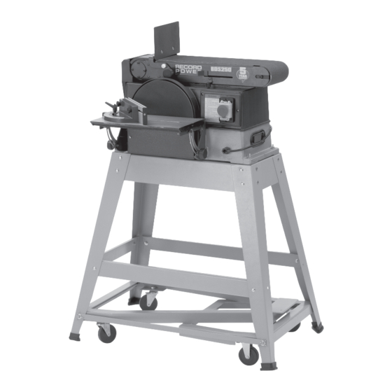
BDS250 10" x 6"
Belt & Disc Sander
Version 3.0
January 2013
Show with optional stand and wheel kit.
It is important to register your product as soon as possible in order to receive efficient after sales
support and be entitled to the full 5 year guarantee. Your statutory rights are not affected.
Kg
Always wear safety glasses when
using woodworking equipment.
To register this product please visit
www.recordpower.info
Please see back cover for contact details.
i
Always read the instructions
provided before using
woodworking equipment.
Kg
Important
For your safety read instructions carefully
before assembling or using this product.
Save this manual for future reference.
Advertisement
Table of Contents

Related Manuals for Record Power BDS250


Summary of Contents for Record Power BDS250
- Page 1 Original Instruction Manual BDS250 10" x 6" Belt & Disc Sander Version 3.0 January 2013 Show with optional stand and wheel kit. To register this product please visit www.recordpower.info It is important to register your product as soon as possible in order to receive efficient after sales support and be entitled to the full 5 year guarantee.
-
Page 2: Table Of Contents
10 Basic Operation 11 Maintenance 12 Troubleshooting 13 Dust Extraction 14 Electrical Connection & Wiring Diagram 15 Exploded Diagram & Parts List 16 Assembly of the Optional BDS250-A Stand 17 Assembly of the Optional BDS250-W Wheel Kit EU Declaration of Conformity... -
Page 3: Explanation Of Symbols
1. Explanation of Symbols THE SYMBOLS AND THEIR MEANINGS SHOWN BELOW MAY BE USED THROUGHOUT THIS MANUAL. PLEASE ENSURE THAT YOU TAKE THE APPROPRIATE ACTION WHEREVER THE WARNINGS ARE USED. Mandatory Instructions Warning Read and fully understand the instruction manual Indicates a risk of severe personal injury or before attempting to use the machine. - Page 4 2. General Health & Safety Guidance - cont. • The floor surface should be sound and level. All of the feet of the 15. Electrical supply machine should make contact with the floor surface. If they do not, either • Electrical circuits should be dedicated to each machine or large enough to re-locate the machine to a more suitable position or use packing shims handle combined motor amp loads.
-
Page 5: Additional Health & Safety For Belt & Disc Sanders
2. General Health & Safety Guidance - cont. 28. Keep cutting tools sharp and clean • Use all machines with extreme care and do not use the machine when you are tired or under the influence of drugs, alcohol or medication. •... -
Page 6: Record Power Guarantee
Guarantee should be made directly to Record Power or its Authorised Distributor Record Power guarantees that for a period of 5 years from the date (for details of the Authorised Distributor in your country please see of purchase the components of qualifying Products (see clauses 1.2.1 your Product manual or check www.recordpower.info for details). -
Page 7: Unpacking And Checking Contents
6. Unpacking and Checking Contents This machine is shipped complete in one carton. For assembly you will need (not included): Separate all parts from packing materials and check each item with illustration and bag of loose parts. Note: Make certain all items are accounted for, before discarding any packing material. -
Page 8: Assembly Instructions
7. Assembly Instructions Fig 7.1 Mounting Belt and Disc Sander to Workbench If belt and disc sander is to be used in a permanent location, it should be fastened securely to a firm supporting surface such as workbench. If mounting to a workbench, holes should be drilled through supporting surface of the workbench using dimensions shown in Fig 7.1. -
Page 9: Installing Table
7. Assembly Instructions - cont. Fig 7.5 Installing Table Fig 7.5. 1. Use 4 M6 x 16 pan head screws to fasten both table support mounts onto the front of the machine. 2. Place the support table with scale onto the table support mount. 3. - Page 10 7. Assembly Instructions - cont. Fig 7.8 Installation of the Sanding Belt, Tensioning & Tracking Warning: To avoid injury from accidental starting, make sure the machine is unplugged before aligning. On the smooth side of the sanding belt, you will find a directional arrow. The sanding belt must run in the direction of this arrow so that the spliced joint does not come apart.
-
Page 11: Getting To Know Your Belt And Disc Sander
8. Getting To Know Your Belt and Disc Sander Fig 8.1 Warning: To avoid injury from accidental start, remove the plug from power source outlet before making any adjustments. Fig 8.1 1. Hex socket head screw. Loosening screw allows belt bed to raise to the vertical position. -
Page 12: Basic Operation
10. Basic Operation Before Using the Sander In the Event of a Blockage or if the Machine Stalls If the machine stalls due to the work piece or sanding belt becoming trapped, switch the machine of immediately by pressing the red button on the switch marked ‘O’. - Page 13 10. Basic Operation - cont. Bevel Sanding Fig 10.1 Fig 10.2 The work table can be tilted from 0º to 45º for bevel sanding. Loosen the table lock knob and tilt the worktable to desired angle as shown, Fig 10.1. Re-tighten table lock knob. Warning: To avoid trapping the work or fingers between the table and sanding surface, the table should repositioned on...
-
Page 14: Sanding Curved Edges
10. Basic Operation - cont. Fig 10.7 Sanding Curved Edges Always sand inside curves on the idler drum as shown in Fig 10.7. Warning: Never attempt to sand the ends of a workpiece on the idler drum, applying the end of the workpiece to the idler drum could cause the workpiece to fly up and result in an injury. -
Page 15: Maintenance
11. Maintenance Lubrication The ball bearings in this machine are packed with grease during manufacture. They require no further lubrication. Warning: For your safety, remove the plug from power source outlet before adjusting or maintaining the belt and disc sander. Frequently blow out or vacuum out any dust that may accumulate inside the motor. -
Page 16: Dust Extraction
Record Power Extractors simultaneously giving maximum suction but in this mode the extractor must Record Power offer a range of high quality dust extractors, we offer both be switched off for 20 minutes every hour. 0.5 micron filtration drum and bag type extractors which filter down 0.5 micron providing protection from harmful fine dusts. -
Page 17: Electrical Connection & Wiring Diagram
14. Electrical Connection & Wiring Diagram Machines supplied for use in the UK are fitted with a 3 pin plug conforming machine. If replacing the original fuse, always fit a fuse of equivalent rating to BS1363, fitted with a fuse conforming to BS1362 and appropriate to the to the original. -
Page 18: Exploded Diagram & Parts List
15. Exploded Diagram & Parts List... - Page 19 15. Exploded Diagram & Parts List Sanding belt 152 x 1219 mm 40 Motor cover 41 Lower safety guard Knob 42 Pan head screw M5 x 8 Washer 43 Thread M6 x 145 Wing screw 44 Rubber sleeve Sunk head screw M6 x 16 45 Support stem Work table for belt 46 Lock base sander belt...
-
Page 20: Assembly Of The Optional Bds250-A Stand
16. Assembly of the Optional BDS250-A Stand. CAUTION! The machine is heavy. Additional help or a Fig. 16.1 suitable lifting device or support will be required for lifting the machine onto the stand. The stand comes as a self assembly unit Fig.16.1. - Page 21 16. Assembly of the Optional BDS250-A Stand. Note: When assembling this legstand do Fig.16.2 Fig.16.6 not fully tighten the nuts and bolts until the assembly is complete. LONG MID BRACE SUPPORTS When fitting the optional pedal wheel kit during initial assembly of the...
- Page 22 16. Assembly of the Optional BDS250-A Stand 1. Feed the long fixing bolts up through the Fig.16.8 stand and secure the four corners using the washers and bolts provided Fig.16.8. The whole LONG FIXING BOLTS stand can now be fully tightened ready for the machine to be fitted.
-
Page 23: Assembly Of The Optional Bds250-W Wheel Kit
17. Assembly of the Optional BDS250-W Pedal Wheel Kit Pedal Fig.17.1 Flat washer Hex nut Spring washer Washer Axle Split pin Rotating casters Hex bolt Casters Release catch Hex nut Flat washer Operating frame Brace support bar When fitting the optional pedal wheel kit during initial assembly 8. - Page 24 17. Assembly of the Optional BDS250-W Pedal Wheel Kit OPERATING FRAME Fig.17.2 Fig.17.10 Fig.17.6 FIXING PIN FLATTENED AREAS RELEASE CATCH PEDAL Fig.17.11 Fig.17.3 Fig.17.7 PEDAL AXLE RELEASE CATCH FIXING PIN Fig.17.8 Fig.17.4 REAR OF MACHINE Fig.17.5 Fig.17.9 AXLE BRACE SUPPORT BAR...
-
Page 25: Eu Declaration Of Conformity
EU Declaration of Conformity Cert No: EU / BDS250 / 1 RECORD POWER LIMITED, Centenary House, 11 Midland Way, Barlborough Links, Chesterfield, Derbyshire S43 4XA declares that the machinery described:- 1. Type: Belt & Disc Sander 2. Model No: BDS250 3. - Page 28 Woodworking Machinery & Accessories United Kingdom Eire Australia New Zealand Record Power Ltd Record Power Ltd Tools 4 Industry Tools 4 Industry Centenary House, 11 Midland Way Centenary House, 11 Midland Way Po Box 3844 Po Box 276079 Barlborough Links, Chesterfield...
Need help?
Do you have a question about the BDS250 and is the answer not in the manual?
Questions and answers