
Related Manuals for AAS Ascent X1

Summary of Contents for AAS Ascent X1
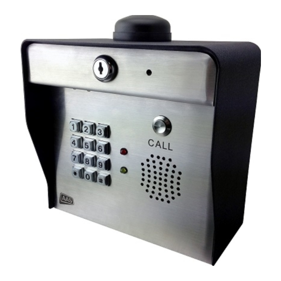
- Page 1 Installation and Operating Manual 16-X1 Cellular Telephone Entry System trol Your “Partner” in Access Con www.americanaccess.com...
-
Page 2: Table Of Contents
Contents Two-Year Limited Warranty PARTS CHECKLIST INTRODUCTION INSTALLATION WIRING CONNECTIONS THE IDLE MODE ACCESS CODES AND FUNCTION CODES GOOD TONES and ERROR TONES PROGRAMMING THE X1 UNIT Program Relay “A” Access Codes - Sub-Mode 1 Delete Individual Access Codes - Sub-Mode 2 Change the Master Code - Sub-Mode 3 Set Sleep Code -- Sub-Mode 4 Set Latch Code -- Sub-Mode 5... -
Page 3: Two-Year Limited Warranty
If your American Access System (AAS) product is defective and returned within two years of purchase, well will repair, or at our option, replace the unit at no charge to you. If we repair your AAS Product, we may use new or reconditioned parts. -
Page 4: Parts Checklist
Parts that are included in the box include the following items. If any of the items is missing, contact American Access Systems (AAS) Item Ascent X1 Control Station (w/2 keys) 12VAC Plug-in Transformer ¼”-20 X ½” carriage bolts ¼”-20 hex nuts Tools Needed For Basic Installation •... -
Page 5: Introduction
If any parts are missing from the package, contact American Access Systems immediately. Mounting the unit to an AAS gooseneck pedestal (18-001) or double height gooseneck (18-003) Locate the four carriage bolts and four hex nuts found inside the shipping box. -
Page 6: Wiring Connections
ASCENT INTERFACE BOARD- WIRING CONNECTIONS Board Input/Output • Status- Provides gate status “open or closed” to the devices administrator • Power- Power input from provided transformer • Relay A-Termination for primary device to be controlled • Relay B- Termination for secondary device to be controlled •... -
Page 7: The Idle Mode
THE IDLE MODE When the desired connections are complete and power is supplied to the unit, the unit will be in the IDLE MODE. The IDLE MODE is the normal mode of operation, meaning the unit is ready to accept input from the keypad. When in the IDLE MODE, you have approximately 4 seconds between key presses. -
Page 8: Good Tones And Error Tones
GOOD TONES and ERROR TONES The Ascent X1 unit sounds an audible tone each time a key is pressed. The star (*) key serves as the clear key and a double tone is sounded when the star (*) key is pressed. The pound (#) key is the exit key and exits the programming mode any time it is pressed. - Page 9 PROGRAMMING THE ASCENT X UNIT To access the program mode, enter the MASTER CODE. When the correct MASTER CODE is entered the yellow LED will light and a GOOD TONE will sound. You can now enter any of ten programming SUB MODES described below. SUB MODE NUMBER CODE DESCRIPTION Program an Access Code(s) (Relay A)
-
Page 10: Program Relay "A" Access Codes -- Sub-Mode 1
• To enter new codes if the memory is full, you must first delete codes some of the codes already in memory. • Contact AAS if there seems to be a problem programming additional codes. Page 10 American Access Systems / Security Brands, Inc. -
Page 11: Delete Individual Access Codes -- Sub-Mode 2
Delete Individual Access Codes -- Sub-Mode 2 To delete programmed Access Codes: • Enter the Master Code • Unit will sound a GOOD TONE • Enter the numeral 2 • Unit will sound a GOOD TONE • Enter the Access Code you want to delete •... -
Page 12: Set Sleep Code -- Sub-Mode 4
Set Sleep Code -- Sub-Mode 4 DETAILS: The Sleep Code is used to disable all Relay A and Function Codes from the keypad. This feature is most commonly used in applications where no entry is desired after hours. Relay B codes will continue to be valid from the keypad. -
Page 13: Set Latch Code -- Sub-Mode 5
Set Latch Code -- Sub-Mode 5 DETAILS: The Latch Code toggles the state of the main relay (A) of the circuit board. The red LED will remain lit while the relay is in the latched position. The latch code is useful in applications where the gate is desired to hold open. If the operator’s close circuit is controlled by loops, timers, etc., they will be overridden by the latched state of the relay and the gate will hold open. -
Page 14: Enable Or Disable The "Three Strikes
Enable or Disable the “Three Strikes … You’re Out” feature -- Sub-Mode 8 DETAILS: This “anti-tampering” feature is designed to help keep an unauthorized individual from continually entering codes until they “hit” a programmed Access Code. When the “Three Strikes …You’re Out” feature is enabled, if anyone enters 3 incorrect Access Codes within 90 seconds, the “Three Strikes …You’re Out”... -
Page 15: Event Input -- Sub-Mode 9
Event Input -- Sub-Mode 9 DETAILS: Programming Sub-Mode 9 allows a user with Master Code privileges to program the unit to connect to an external device to control a specific function. Note: Relay A codes can be turned off by an external switch. When inactive, all Relay “A” codes will be disabled. -
Page 16: Erase All Codes -- Sub-Mode 0
Erase All Codes -- Sub-Mode 0 Caution: This is a destructive Programming Mode. Completing the following steps will erase all Access Codes except for the factory default Master Code (1 2 5 1). Use with Caution. DETAILS: This Sub-Mode should rarely be used unless you want to completely erase all Access Codes entered. This action will not change the Master Code. -
Page 17: Resetting The X1 Unit
RESETTING THE ASCENT UNIT The Ascent X1 has two special reset types: Master Reset and Unit Reset. Choose the procedure that you want to use carefully. Master Reset • Should be used if the Master Code is lost or forgotten. The procedure will reset the Master Code to the 1 2 5 1. -
Page 18: Master Reset
MASTER RESET Follow these steps exactly. If you make an error, an ERROR will occur (you will hear a low ERROR tone) and you will need to start over from Step 1. 1. Open the unit face plate using the key provided. 2. -
Page 19: Troubleshooting
TROUBLESHOOTING Problem Solution 1 2 5 1 is the Master Code or programming access code. When I enter 1 2 5 1 on the keypad the gate will It will not open the gate unless the unit is in sleep mode. not open. -
Page 20: Customer Service And Tech Support
Customer Service and Tech Support Customer Service: 303-799-9757 Customer service is available free of charge. Hours are 8:00 a.m. to 4:30 p.m. MST. If you call, please have your Model and Serial Number to help our Technicians assist you. E-Mail: customerservice@securitybrandsinc.com Technical Support: 303-799-9757 Technical support is available free of charge. -
Page 21: Notes
Notes Use this space to keep a record of Access Codes and the MASTER Code Page 21 American Access Systems / Security Brands, Inc. - Page 22 Notes Use this space to keep a record of Access Codes and the MASTER Code Page 22 American Access Systems / Security Brands, Inc.
- Page 23 Notes Use this space to keep a record of Access Codes and the MASTER Code Page 23 American Access Systems / Security Brands, Inc.
- Page 24 Your “Partner” in Access Control www.securitybrandsinc.com SECURITY BRANDS...
Need help?
Do you have a question about the Ascent X1 and is the answer not in the manual?
Questions and answers