Shure ULXS4 User Manual
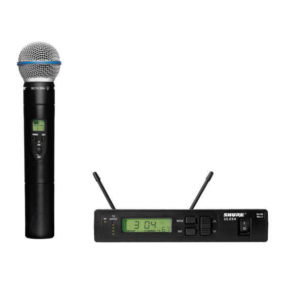
Ulx wireless system
Hide thumbs
Also See for ULXS4:
- User manual (52 pages) ,
- User manual supplement (20 pages) ,
- User manual (28 pages)

Related Manuals for Shure ULXS4


Summary of Contents for Shure ULXS4
- Page 1 ULX Wireless System Shure ULX Wireless ULX sans fil de Shure Sistema inalámbrico ULX de Shure Sistema ULX Sem Fio da Shure ©2014 Shure Incorporated 27A15788 (Rev. 4)
-
Page 3: Ulx System Components
• Mount antennas more than 40 cm (16 inches) apart. Distribution Amplifier combines antennas and power supplies for • Use Shure UA825 or UA850 low-loss coaxial antenna cable multiple receivers (or any 50 ohm, low-loss cable such as RG-8U). Visit www.shure.com for more information on wireless antenna accessories. -
Page 4: Rack Installation
• Use the lock feature to avoid accidental listed below. For detailed information on bat- Note: Remaining battery life varies with battery type. muting of the microphone during a tery performance, contact Shure Applications performance. Engineering. Recommended: • Lithium (16 hours) Battery Indicator •... -
Page 5: Single System
To reduce setup time, you can manually set up the group and channels before arriving at 4. IMPORTANT: Leave the first transmitter powered on while setting up the venue. Visit www.shure.com for a list of groups and channels that are anticipated to be free of interference in a particular city or region. -
Page 6: Audio Output
10 s Audio Output Receiver Output Level Adjusts the level of the receiver's audio outputs. Audio Output Connectors ULXP4, ULXS4 ULXP4 Balanced XLR: Connect to a mixer or other professional audio input. Use the MIC/LINE switch to adjust for microphone or line-level inputs. -
Page 7: Transmitter Gain
Transmitter Gain Locking the Receiver (ULXP4 Only) For best audio quality, adjust transmitter gain so only the green and This feature prevents accidental setting changes. yellow TX AUDIO LEDs flicker. (Occasional illumination of the red LED is okay.) ULXP4 Green = nominal Yellow = peak Red = overload ULX1... -
Page 8: Troubleshooting
Troubleshooting No power: Check battery and power supply connections and voltage. No audio: If the antenna and battery indicators do not appear on the re- Check the power switch on the transmitter. ceiver, then it is not receiving a signal from the transmitter. Make sure the transmitter and receiver are tuned to the same group and channel. -
Page 9: Important Product Information
Authorized European representative: tion, and on the selected frequency. Shure strongly urges the user to Shure Europe GmbH contact the appropriate telecommunications authority concerning proper Headquarters Europe, Middle East & Africa licensing, and before choosing and ordering frequencies. -
Page 10: Specifications
Specifications ULXS4, ULXP4 Transmitter Input RF Carrier Range 470,000–865,000 MHz varies by region Connector Dimensions 4-Pin male mini connector (TA4M) Working Range 43 x 214 x 163 mm (1.72 x 8.56 x 6.52 in.), 100 m (300 ft) typical ULXS4... - Page 11 ULX FREQUENCIES FOR EUROPEAN COUNTRIES ULX-G3E 470 - 506 MHz, max. 30 mW ULX R4 784–820 MHz max. 30 mW Country Code Frequency Range Country Code: Frequency Range Code de Pays Gamme de frequences Code de Pays: Gamme de frequences Codice di paese Gamme di frequenza Codice di paese:...
- Page 12 ULX SYSTEM COMPATIBILITY GUIDE FOR FREQUENCY BAND G3E (470–506 MHz) Group 1 Group 2 Group 3 Group 4 Group 5 Group 6 Group 7 France France France France Full Range Full Range Full Range Channel preferred: preferred: preferred: preferred: max. # of compatible max.
- Page 13 ULX SYSTEM COMPATIBILITY GUIDE FOR FREQUENCY BAND K2E (606-642 MHz) Group 1 Group 2 Group 3 Group 4 Group 5 Group 6 Group 7 Group 8 Group 9 Full Range Full Range Full Range Full Range Full Range Full Range U.K.
- Page 14 ULX SYSTEM COMPATIBILITY GUIDE FOR FREQUENCY BAND X7 (925 - 937.5 MHz) Group 1 Group 2 Group 3 Group 4 Group 5 Group 6 Group 7 Group 8 Group 9 CHANNEL more freqs. more freqs. more freqs. more freqs. more freqs. more freqs.
Need help?
Do you have a question about the ULXS4 and is the answer not in the manual?
Questions and answers