
Related Manuals for Digilock DK-ATS


Summary of Contents for Digilock DK-ATS
- Page 1 DK-ATS & DK-APS Shared & Assigned Use Functionality Manual applies to all pull handle & no-pull handle models, surface/recess mounts and wood/metal doors...
-
Page 2: Table Of Contents
Door Preparation Instructions _________________________________ 14 Installation Instructions ______________________________________ 18 Wood Recess Mount _______________________________________________ 22 Required Components __________________________________________ 23 Door Preparation Instructions _________________________________ 24 Installation Instructions ______________________________________ 28 Identifying Your Digilock Lock Function _____________________________ 32 Programming Instructions ________________________________________ 34 Lock Interface Overview ________________________________________ 35 Key Guide _____________________________________________________ 36 Initializing Locks ______________________________________________ 36 Express Registration __________________________________________ 37 Register Additional Manager Bypass Keys ________________________ 38... - Page 3 (iii) such defect has not been caused by corrosion, exposure to moisture, or ordinary wear and tear. Digilock lock products are not designed or intended for exterior use or where exposed to moisture. Any exterior use where exposed to moisture is not covered by any warranties and voids any warranties.
-
Page 5: Metal Door Installations
Metal Door Installations Required Components Metal Door Mounting Types Surface Mount Metal Door Installation Recessed Cup Metal Door Installation 3-Hole Lock Plug Removal Padlock Hasp Removal... - Page 6 Required Components Digilock Lock Parts Note: Confirm that all lock parts are present. If there are damaged or missing parts contact your Digilock Product Support Specialist. 1-Front Unit with Screw Posts 1-Motorized Rear Unit (Both body styles shown) (Both Dead Bolt & Dead Latch shown)
- Page 7 Metal Door Mounting Types Digilock is compatible with a majority of industry standard 3-hole configuration, latch and handle types. Some door types may need disassembly or modifications prior to installation. Recessed Cup with Single Point Latch Standard Lift Multi-Point Latch...
- Page 8 Surface Mount Metal Door Installation Parts Note: For demonstration purposes the standard body with pull-handle and dead bolt rear unit will be shown. 1-Front Unit With-Pull Handle 1-Plastic Ring 1-Rear Unit 2-Locking Nuts Required Tools 3/8” Socket (deep socket required) Surface Mount Metal Door Installation Steps Note: Prior to installation the door must be clear of any obstructions.
- Page 9 Step 3 Step 4 While holding the front unit (A) against the front of the Slide the front unit (A) and rear unit (C) together door, place the rear unit (C) against the rear face of making sure that the pins of the rear unit connector align the door, aligning its mounting holes with the mounting with the female connector of the front unit (A).
- Page 10 Recessed Cup Metal Door Installation Parts Note: For demonstration purposes the dead bolt rear unit will be shown. 1-Front Unit No-Pull Handle 1-Plastic Ring 1-Rear Unit 2-Locking Nuts Required Tools 3/8” Socket (deep socket required) Recessed Cup Metal Door Installation Steps Note: Prior to installation the door must be clear of any obstructions.
- Page 11 Step 3 Step 4 While holding the front unit (A) against the front of the Slide the front unit (A) and rear unit (C) together door, place the rear unit (C) against the rear face of making sure that the pins of the rear unit connector align the door, aligning its mounting holes with the mounting with the female connector of the front unit (A).
- Page 12 Door Prep - 3-Hole Lock Plug Removal Most metal lockers will come with a 3 point dial combo metal plug. This will need to be removed in order to install your Digilock Lock. Single or Standard Lift with Mounted Plug...
- Page 13 Note: Digilock manufactures an optional Back Plate to cover the padlock hasp hole. For more information please contact your Digilock Product Specialist.
-
Page 15: Wood Surface Mount
Wood Surface Mount Required Components Door Preparation Instructions Installation Instructions... -
Page 16: Required Components
Required Components Digilock Lock Parts Note: Confirm that all lock parts are present. If there are damaged or missing parts contact your Digilock Product Support Specialist. 1-Front Unit with Nut Posts 1-Motorized Rear Unit (Both body styles shown) (Both Dead Bolt & Dead Latch shown) -
Page 17: Door Preparation Instructions
Center line Door Preparation Instructions Note: Skip these steps if a Digilock compatible industry standard 3-hole configuration already exists on your door. Lock Mounting Holes Required Items: Lock Mounting Drill Template: See page 16 (print and cut out template) Pencil: To mark door and template... - Page 18 Strike Plate Installation Note: Skip these steps if a Digilock compatible strike plate is already present. Required Hardware & Tools: • Digilock Strike Plate with 3-Self-Tapping Screws • Pencil: To mark screw holes • Phillips Screwdriver: #1 or Cordless drill (with torque adjustment) and a phillips driver recommended...
- Page 19 Lock Mounting Drill Template Note: Use the corresponding side of the template for mounting the lock. All measurements in thousandths of an inch and millimeters ALIGN EDGE OF ALIGN EDGE OF STRIKE PLATE HERE STRIKE PLATE HERE LEFT RIGHT CLOSING DOOR CLOSING DOOR .300 7.62 (mm)
- Page 20 Door Prep Requirements Before installing, your door must be prepped with a Strike Plate (Figure A) and lock mounting holes (Figure B). NOTE: See Door Preparation Instructions for more information on pages 14-16. FIG. A FIG. B Strike Plate Lock Handing To change handing: 1) Disconnect the front unit from the rear unit.
-
Page 21: Installation Instructions
Installation Instructions Digilock Wood Surface Mount Lock Parts Note: For demonstration purposes the standard body with pull-handle and dead bolt rear unit will be shown. 1-Front Unit 1-Plastic Ring 1-Rear Unit 1-Pin Extender 2-Phillips Head Screws* 2-Split Lock Washers * Screws lengths vary based on door thickness. - Page 22 Step 1 Step 1 Place the plastic ring (B) onto the front unit (A). Place the pin extender (D) on the connector pins of the rear unit (C). NOTE: Do not touch the rear unit connector pins (male connector) against any metal or other conductive surfaces.
- Page 23 Step 5 Step 6 While holding the front unit (A) against the front of the Slide the front unit (A) and rear unit (C) together door, bring the rear unit (C) against the rear face of making sure that the pins of the rear unit connector the door, aligning the screws in the rear unit with the align with the pins of the front unit connector and hand mounting nut posts from the front unit.
-
Page 25: Wood Recess Mount
Wood Recess Mount Required Components Door Preparation Instructions Installation Instructions... -
Page 26: Required Components
Required Components Digilock Lock Parts Note: Confirm that all lock parts are present. If there are damaged or missing parts contact your Digilock Product Support Specialist. 1-Front Unit with Screw Posts 1-Motorized Rear Unit (Both body styles shown) (Both Dead Bolt & Dead Latch shown) -
Page 27: Door Preparation Instructions
Center line Door Preparation Instructions Note: Skip these steps if a Digilock compatible industry standard 3-hole configuration already exists on your door. Lock Mounting Holes Required Items: Lock Mounting Drill Template: See page 26 (print and cut out template) Pencil: To mark door and template... - Page 28 Strike Plate Installation Note: Skip these steps if a Digilock compatible strike plate is already present. Required Hardware & Tools: • Digilock Strike Plate with 3-Self-Tapping Screws • Pencil: To mark screw holes • Phillips Screwdriver: #1 or Cordless drill (with torque adjustment) and a phillips driver recommended...
- Page 29 Lock Mounting Drill Template Note: Use the corresponding side of the template for mounting the lock. All measurements in thousandths of an inch and millimeters ALIGN EDGE OF ALIGN EDGE OF STRIKE PLATE HERE STRIKE PLATE HERE LEFT RIGHT CLOSING DOOR CLOSING DOOR .300 7.62 (mm)
- Page 30 Door Prep Requirements Before installing, your door must be prepped with a Strike Plate (Figure A) and must be Mortised to receive recessed lock (Figure B). NOTE: See Door Preparation Instructions for more information on page 24-26. FIG. A FIG. B Strike Plate Lock Handing To change handing:...
-
Page 31: Installation Instructions
Installation Instructions Digilock Wood Recess Mount Lock Parts Note: For demonstration purposes the standard body with pull-handle and dead bolt rear unit will be shown. 1-Front Unit 1-Rear Unit 1-Pin Extender 2-Locking Nuts Required Tools 3/8” Socket (deep socket required) - Page 32 Step 1 Step 2 Place the pin extender (C) on the connector pins of the Place the mounting screw posts of the front unit (A) rear unit (B). through the lock recessed mounting holes on the front of the door. NOTE: Do not touch the rear unit connector pins (male connector) against any metal or other conductive surfaces.
- Page 33 Step 5 Step 6 Test the operation several times (as indicated below) while the door is open. Close the door and test the unit again. Make sure there is no binding between the bolt/latch and the door strike plate and/ or frame.
-
Page 35: Identifying Your Digilock Lock Function
Identifying Your Digilock Lock Function Shared Use Lock Model Assigned Use Lock Model... - Page 36 Identifying Your Digilock Lock Function Before initializing/programming your locks it is important to identify the functionality of the lock you have in order to determine which programming instructions will be applicable. Shared Use Lock Model • The rear unit has a Dead Bolt.
-
Page 37: Programming Instructions
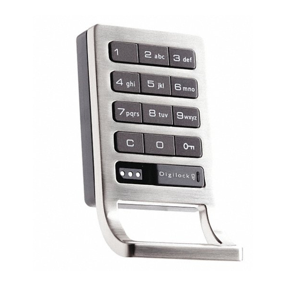
Lock Interface Overview Lock Interface Overview Key Guide Digilock DK-Series Key Guide Initializing Locks Digilock DK-Series Key Initialization Guide Express Registration EXPRESS Registration Register Additional Manager Bypass Keys How to Register Additional Manager Bypass Keys For Lost or Stolen Keys... - Page 38 Lock Interface Overview Key Insertion Digilock Logo must face up. Alpha Numeric Keypad C Button Key Symbol Button Key Insert LED light Usage Indicator Pull Handle Key Guide: Programming Key (Yellow) Manager Bypass Key (Black) • Registers Manager Bypass Key(s) •...
-
Page 39: Initializing Locks
Initializing Lock These steps will initialize and register one or more Manager Bypass Keys to one lock. Start at locker #1. Touch the Programming Key (yellow) While the LED light is solid, touch each of the to the key slot for one full second. Manager Bypass Key(s) (black) to the key slot one at a time. -
Page 40: Express Registration
Express Registration These steps help speed registration and initialization of multiple new locks. Go to the lock that was programmed in Touch the Programming Key (yellow) to the key slot. Step 1 on page 36. A two tone beep will be heard and the LED light will turn off. -
Page 41: Register Additional Manager Bypass Keys
Register Additional Manager Bypass Keys To add additional Manager Bypass Key to locks that have been previously programmed. Go to a lock that has been programmed with existing Touch the Programming Key (yellow) to the key slot of Manager Bypass Keys. the lock for one full second. -
Page 42: For Lost Or Stolen Keys
The following steps will erase registration of all Manager Bypass Keys. Collect all remaining Manager Bypass Key(s) or Go to locker #1 and press: = ` 55 ` order additional keys from your Digilock product The LED light will flash. representative. Touch the Programming Key (yellow) to the key slot Touch the Programming Key (yellow) to the key slot for one full second. -
Page 43: Shared Use Programming
Shared Use Programming USE QR CODES TO WATCH THE VIDEO VERSION Automatic Unlock Feature Shared use Setting the Automatic Unlock Feature LED Light Function Shared use Disabling the LED light... -
Page 44: Automatic Unlock Feature
Automatic Unlock Feature Automatic Unlock is an option that will only activate when it is programmed. It can be disabled at any time with a registered Manager Bypass Key. To Enable Automatic Unlock Touch a registered Manager Bypass Press the through for the Press:... -
Page 45: Led Light Function
LED light Function The purpose of the LED light is to provide a usage indicator for when the locks are being used in a shared use environment. In the event that the lock(s) are assigned to one user (converted to assigned use) it is advisable to disable the LED light with a registered Manager Bypass Key in order to extend the battery life. -
Page 47: Shared Use Instructions
Shared Use Instructions USE QR CODES TO WATCH THE VIDEO VERSION Shared Use Lock Use Instructions To Operate with a User Code To Operate with an ADA User Key To Operate with a Manager Bypass Key To Operate with a Programming Key... -
Page 48: To Operate With A User Code
To Operate with a User Code To Lock To Unlock 1) Find an available lock. 1) At same lock. 2) Press: 2) Press: _ _ _ _ _ _ _ _ (any four-digit code) (same code used to lock) Note: If an incorrect User Code is entered three consecutive times, the lock will go into “Sleep State” for one full minute or until a registered Manager Key (black) is touched to the lock. -
Page 49: To Operate With A Manager Bypass Key
To Operate with a Manager Bypass Key To Lock To Unlock Touch a registered Manager Bypass Key (black) to Touch a registered Manager Bypass Key (black) to key slot. key slot. To Operate with a Programming Key To Lock Touch the Programming Key (yellow) to key slot. Press: then To Unlock... -
Page 51: Assigned Use Programming
Assigned Use Programming USE QR CODES TO WATCH THE VIDEO VERSION Assigned Use Setting the User Credentials To Change the User Code Assign an ADA User Key... -
Page 52: To Change The User Code
To Change the User Code Assigned use locks have the default user code of once initialized. 1 2 3 4 Insert a registered Manager Bypass Key (black) to Press: then key slot. The LED light will turn solid. Press: Repeat: _ _ _ _ _ _ _ _ (key in any four-digit code) -
Page 53: Assign An Ada User Key
Assign an ADA User Key Insert a registered Manager Bypass Key (black) to Press: then key slot. Lock will emit two tone beep and the LED light will turn solid. Touch an ADA User Key (blue) to key slot. Lock will emit two tone beep and the LED light will turn off. -
Page 55: Assigned Use Instructions
Assigned Use Instructions USE QR CODES TO WATCH THE VIDEO VERSION Assigned Use Lock Use Instructions To Operate with an Assigned User Code To Operate with an Assigned ADA User Key To Operate with a Manager Bypass Key To Operate with a Programming Key... - Page 56 To Operate with an Assigned User Code To Unlock To Lock Simply close the door. 1) Press: _ _ _ _ (assigned four-digit user code) 2) Open the door. The lock will automatically relock after 6-8 seconds. Note: If an incorrect User Code is entered three consecutive times, the lock will go into “Sleep State” for one full minute or until a registered Manager Key (black) is touched to the lock.
-
Page 57: To Operate With A Manager Bypass Key
To Operate with a Manager Bypass Key To Unlock To Lock 1) Touch a registered Manager Bypass Key (black) Simply close the door. to key slot. 2) Open the door. The lock will automatically relock after 6-8 seconds. To Operate with a Programming Key To Unlock 1) Touch the Programming Key (yellow) to key slot Press:... -
Page 59: Troubleshooting
Troubleshooting USE QR CODES TO WATCH THE VIDEO VERSION Troubleshooting Common Lock Indicators Battery Replacement Overall Dimensions Contact Information... - Page 60 If you are unsuccessful, please contact Digilock Customer Support. Lock Usage Indicators The Digilock locks are designed to emit audible and visual feedback during regular use as well as when the lock might be encountering difficulties. The following are the most common lock usage indicators and their meanings.
- Page 61 Battery Replacement The batteries are located in the rear unit of the lock. Note: It is not necessary to remove the mounting hardware or remove the lock from door to change the batteries. Remove the four screws as indicated above. Remove the cover plate.
- Page 62 Standard Body Dimensions 0.23 in Standard No-Pull Nut Post Length (6 mm) 0.47 in (12 mm) 2.86 in (73 mm) 2.14 in 0.38 in (54 mm) (10 mm) 3.87 in (98 mm) 0.79 in (20 mm) Screw Post Lenght 0.91 in (23 mm) Standard Pull 1.28 in...
- Page 63 Rear Unit Dimensions Motorized Dead Bolt 2.80 in 2.64 in (71 mm) (67 mm) 0.50 in 3.73 in (13 mm) (95 mm) 1.35 in (34 mm) 0.25 in (6 mm) Motorized Dead Latch 2.64 in 2.80 in (67 mm) (71 mm) 0.50 in 3.71 in (13 mm)
- Page 64 Contacting Support For additional product information including instructional videos. Please visit us online at: www.digilock.com/us/service.html Via email: support@digilock.com Directly at: Digilock 9 Willowbrook Court Petaluma, CA 94954 Phone: (707) 766-6000 Toll-Free Phone: (800) 590-0984 (US only) Fax: (707) 766-6226 Toll-Free Fax: (800) 989-4221 (US only)
- Page 66 ™ Digilock Lockup Celáre Numeris security people 9 Willowbrook Court Petaluma • Ca 94954 • USA phone: 707. 766.6000 fax: 707. 766.6226 www.digilock.com...
Need help?
Do you have a question about the DK-ATS and is the answer not in the manual?
Questions and answers