Table of Contents
Advertisement
This publication, including photographs, illustrations and software, is under the
protection of international copyright laws, with all rights reserved. Neither this
user's guide, nor any of the material contained herein, may be reproduced without
the express written consent of the manufacturer.
The information in this document is subject to change without notice. The manu-
facturer makes no representations or warranties with respect to the contents hereof
and specifically disclaims any implied warranties of merchantability or fitness for
any particular purpose. Further, the manufacturer reserves the right to revise this
publication and to make changes from time to time in the content hereof without
obligation of the manufacturer to notify any person of such revision or changes.
Trademarks
IBM, VGA, and PS/2 are registered trademarks of International Business Ma-
chines.
Intel, Pentium/II/III, Pentium 4, Celeron and MMX are registered trademarks of
Intel Corporation.
Microsoft, MS-DOS and Windows 98/ME/NT/2000/XP are registered trademarks
of Microsoft Corporation.
AMI is a trademark of American Megatrends Inc.
It has been acknowledged that other brands or product names in this manual are
trademarks or the properties of their respective owners.
Static Electricity Precautions
1. Don't take this motherboard and components out of their original static-
proof package until you are ready to install them.
2. While installing, please wear a grounded wrist strap if possible. If you
don't have a wrist strap, discharge static electricity by touching the bare
metal of the system chassis.
3. Carefully hold this motherboard by its edges. Do not touch those compo-
nents unless it is absolutely necessary. Put this motherboard on the top of
static-protection package with component side facing up while installing.
Pre-Installation Inspection
1. Inspect this motherboard whether there are any damages to components
and connectors on the board.
2. If you suspect this motherboard has been damaged, do not connect power
to the system. Contact your motherboard vendor about those damages.
Motherboard User's Guide
P17G/1333 Series, V1.0A
i
Copyright © 2007
All Rights Reserved
August 2007
Advertisement
Table of Contents

Subscribe to Our Youtube Channel
Related Manuals for ECS P17G/1333 Series


Summary of Contents for ECS P17G/1333 Series
-
Page 1: Static Electricity Precautions
1. Inspect this motherboard whether there are any damages to components and connectors on the board. 2. If you suspect this motherboard has been damaged, do not connect power to the system. Contact your motherboard vendor about those damages. Copyright © 2007 All Rights Reserved P17G/1333 Series, V1.0A August 2007... -
Page 2: Table Of Contents
Motherboard User’s Guide Table of Contents Trademarks ......................i Static Electricity Precautions ..................i Pre-Installation Inspection ..................... i Chapter 1: Introduction ..................1 Key Features ........................1 Package Contents ......................4 Chapter 2: Motherboard Installation .............. 5 Motherboard Components .................... 6 I/O Ports .......................... - Page 3 Motherboard User’s Guide Notice: Owing to Microsoft’s certifying schedule is various to every supplier, we might have some drivers not certified yet by Microsoft. Therefore, it might happen under Windows XP that a dialogue box (shown as below) pop out warning you this software has not passed Windows Logo testing to verify its compatibility with Windows XP.
-
Page 4: Chapter 1 Introduction
Note: 1. Hyper-Threading technology enables the operating system into thinking it’s hooked up to two processors, allowing two threads to be run in parallel, both on separate ‘logical’ processors within the same physical processor. 2. Under ECS validation, this motherboard is able to support FSB 1333 MHz. Chipset... -
Page 5: Memory Support
Motherboard User’s Guide System Memory Controller Support • -Supports DDR2 SDRAM with up to maximum memory of 2 GB PCI Express Graphics Interface Support • -One PCIEX16 slot for Graphic Interface PCI Bus Interface • -Supports PCI Revision 2.3 Specification at 33 MHz Integrated Serial ATA Host Controller •... - Page 6 Chapter 1: Introduction Onboard I/O Ports • Two PS/2 ports for mouse and keyboard • One serial port • One VGA port • Four USB ports • One LAN port (optional) • Audio jacks for microphone, line-in and line-out Onboard LAN (optional) The onboard LAN controller provides the following features: •...
-
Page 7: Package Contents
Motherboard User’s Guide Dimensions Micro ATX form factor of 244 x 210 mm • Note: Hardware specifications and software items are subject to change without notification. Package Contents Your motherboard package ships with the following items: The motherboard The User’s Guide One diskette drive ribbon cable (optional) One IDE drive ribbon cable The Software support CD... -
Page 8: Chapter 2 Motherboard Installation
Chapter 2: Motherboard Installation Chapter 2 Motherboard Installation To install this motherboard in a system, please follow these instructions in this chapter: Identify the motherboard components Install a CPU Install one or more system memory modules Make sure all jumpers and switches are set correctly Install this motherboard in a system chassis (case) Connect any extension brackets or cables to headers/connectors on the motherboard... -
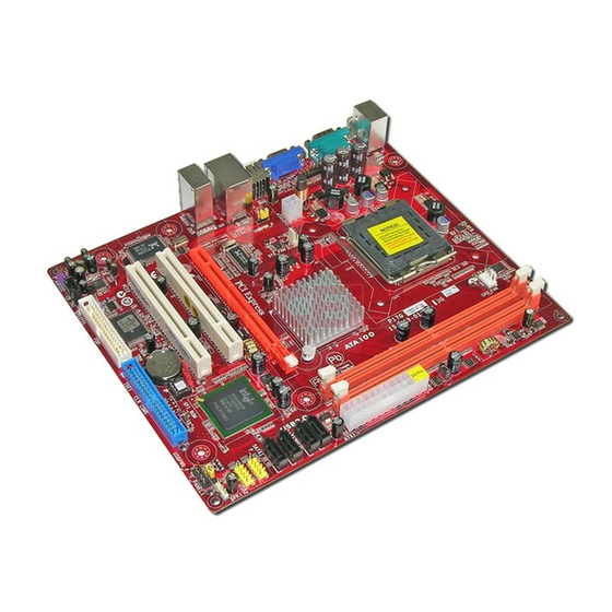
Page 9: Motherboard Components
Motherboard User’s Guide Motherboard Components... - Page 10 Chapter 2: Motherboard Installation ITEM LABEL COMPONENTS LGA775 Socket for Intel ® Core™2 Duo/ CPU Socket Celeron ® D CPUs CPU_FAN CPU cooling fan connector DIMM1/2 240-pin DDR2 SDRAM slots ATX1 Standard 24-Pin ATX Pow er connector SATA1~4 Serial ATA connectors F_USB1~2 Front Panel USB headers SPK1...
-
Page 11: I/O Ports
Motherboard User’s Guide I/O Ports The illustration below shows a side view of the built-in I/O ports on the motherboard. Use the upper PS/2 port to connect a PS/2 pointing PS2 Mouse device. Use the lower PS/2 port to connect a PS/2 PS2 Keyboard keyboard. -
Page 12: Installing The Processor
Chapter 2: Motherboard Installation Installing the Processor This motherboard has a LGA775 socket for the latest Intel® Core 2 Duo/ Celeron D processors. When choosing a processor, consider the performance ® requirements of the system. Performance is based on the processor design, the clock speed and system bus frequency of the processor, and the quantity of inter- nal cache memory and external cache memory. -
Page 13: Installing Memory Modules
Motherboard User’s Guide A. Read and follow the instructions shown on the sticker on the CPU cap. B. Unload the cap · Use thumb & forefinger to hold the lifting tab of the cap. · Lift the cap up and remove the cap completely from the socket. - Page 14 Chapter 2: Motherboard Installation Over its predecessor DDR SDRAM, DDR2 SDRAM offers greater bandwidth and density in a smaller package along with a reduction in power consumption. In addition, DDR2 SDRAM offers new features and functions that enable a higher clock rate and data rate operations of 400 MHz, 533 MHz and 667 MHz.
- Page 15 Motherboard User’s Guide Please check the table below for the CPU FSB frequency and its corresponding memory support frequency. CPU FSB Frequency Memory Support Frequency DDRII533, DDRII667* 1333 DDRII533, DDRII667 1066 DDRII400, DDRII533, DDRII667 DDRII400, DDRII533 *When you use a FSB1333-CPU on this motherboard, it will run at DDRII500 if you adopt a DDRII533 memory module;...
- Page 16 Chapter 2: Motherboard Installation Table A: DDR2 (memory module) QVL (Qualified Vendor List) The following DDR2 667/533 memory modules have been tested and qualified for use when you use a FSB 1333-CPU on this motherboard. Type Size Vendor Module Name Corsair VC256MB533D2 4PB11D9CHM Elpida...
-
Page 17: Jumper Settings
Motherboard User’s Guide Jumper Settings Connecting two pins with a jumper cap is SHORT; removing a jumper cap from these pins, OPEN. CLR_CMOS: Clear CMOS Jumper Use this jumper to clear the contents of the CMOS memory. You may need to clear the CMOS memory if the settings in the Setup Utility are incorrect and prevent your motherboard from operating. -
Page 18: Install The Motherboard
Chapter 2: Motherboard Installation Install the Motherboard Install the motherboard in a system chassis (case). The board is a Micro ATX size motherboard. You can install this motherboard in a Micro ATX case. Make sure your case has an I/O cover plate matching the ports on this motherboard. Install the motherboard in a case. -
Page 19: Connecting Optional Devices
Motherboard User’s Guide Connecting Optional Devices Refer to the following for information on connecting the motherboard’s optional devices: F_AUDIO1: Front Panel Audio Header This header allows the user to install auxiliary front-oriented microphone and line- out ports for easier access. Signal Signal PORT1L... - Page 20 Chapter 2: Motherboard Installation Here is a list of headers F_USB1/F_USB2 pin assignments. Signal Signal USBPWR USBPWR USB_FP_P0(-) USB_FP_P1(-) USB_FP_P0(+) USB_FP_P1(+) 10 USB_FP_OC0 Locate the F_USB1/F_USB2 headers on the motherboard. Plug the bracket cable onto the F_USB1/F_USB2 headers. Remove a slot cover from one of the expansion slots on the system chassis.
-
Page 21: Install Other Devices
Motherboard User’s Guide Install Other Devices Install and connect any other devices in the system following the steps below. Floppy Disk Drive The motherboard ships with a floppy disk drive cable that can support one or two drives. Drives can be 3.5" or 5.25" wide, with capacities of 360K, 720K, 1.2MB, 1.44MB, or 2.88MB. - Page 22 Chapter 2: Motherboard Installation On the motherboard, locate the Serial ATA connectors SATA1-4, which support new Serial ATA devices for the highest data transfer rates, simpler disk drive cabling and easier PC assembly. It eliminates limitations of the current Parallel ATA interface, but maintains register compatibility and software compatibility with Parallel ATA.
-
Page 23: Expansion Slots
Motherboard User’s Guide Expansion Slots This motherboard has one PCIEX16 slot and two 32-bit PCI slots. PCIEX16 The PCIEX16 is used to install an external PCI Express graphics card Slot that is fully compliant to the PCI Express Base Specification revision 1.0a. - Page 24 Chapter 2: Motherboard Installation Follow these instructions to install an add-on card: Remove a blanking plate from the system case corresponding to the slot you are going to use. Install the edge connector of the add-on card into the expansion slot. Ensure that the edge connector is correctly seated in the slot.
-
Page 25: Chapter 3 Bios Setup Utility
Motherboard User’s Guide Chapter 3 BIOS Setup Utility Introduction The BIOS Setup Utility records settings and information of your computer, such as date and time, the type of hardware installed, and various configuration settings. Your computer applies the information to initialize all the components when boot- ing up and basic functions of coordination between system components. -
Page 26: Standard Cmos Setup Page
Chapter 3: BIOS Setup Utility You can use cursor arrow keys to highlight anyone of options on the main menu page. Press Enter to select the highlighted option. Press the Escape key to leave the setup utility. Press +/-/ to modify the selected field’s values. Some options on the main menu page lead to tables of items with installed values that you can use cursor arrow keys to highlight one item, and press + + + + + and - - - - - keys to cycle through alternative values of that item. - Page 27 Motherboard User’s Guide IDE Devices Your computer has one IDE channel which can be installed with one or two devices (Master and Slave). In addition, this motherboard supports two SATA channels and each channel allows one SATA device to be installed. Use these items to configure each device on the IDE channel.
-
Page 28: Advanced Setup
Chapter 3: BIOS Setup Utility Press <Esc> to return to the Standard CMOS Setup page. Advanced Setup This page sets up more advanced information about your system. Handle this page with caution. Any changes can affect the operation of your computer. CMOS Setup Utility - Copyright (C) 1985-2005, American Megatrends, Inc. -
Page 29: Advanced Chipset Setup
Motherboard User’s Guide APIC Mode (Enabled) This item allows you to enable or disable the APCI (Advanced Programmable Interrupt Controller) mode. APIC provides symmetric multi-processing (SMP) for systems, allowing support for up to 60 processors. Boot Other Device (Enabled) When enabled, the system searches all other possible locations for an operating system if it fails to find one in the devices specified under the First, Second and Third boot devices. -
Page 30: Integrated Peripherals
Chapter 3: BIOS Setup Utility Share Memory Size (Enabled, 8MB) This item lets you allocate a portion of the main memory for the onboard VGA display application. Press <Esc> to return to the main menu setting page. Integrated Peripherals This page sets up some parameters for peripheral devices connected to the system. CMOS Setup Utility - Copyright (C) 1985-2005, American Megatrends, Inc. -
Page 31: Power Management Setup
Motherboard User’s Guide Serial Port1 Address (3F8&IRQ4) Use this item to enable or disable the onboard COM1/2 serial port, and to assign a port address. Parallel Port Address (378) Use this item to enable or disable the onboard Parallel port, and to assign a port address. Parallel Port Mode (ECP) Use this item to select the parallel port mode. - Page 32 Chapter 3: BIOS Setup Utility PWRON After PWR-Fail (Power Off) This item enables your computer to automatically restart or return to its operating status. Resume On LAN (Disabled) This item allows users to enable or disable LAN activity to wake up the system from a power saving mode.
-
Page 33: Pc Health Status
Motherboard User’s Guide Init Display First (PCI Card) Use this item to select which graphics controller to use as the primary boot devices. Allocate IRQ to PCI VGA (Yes) If this item is enabled, an IRQ will be assigned to the PCI VGA graphics system. You set this value to No to free up an IRQ. -
Page 34: Frequency/Voltage Control
Chapter 3: BIOS Setup Utility SMART Fan Control (Disabled) This item allows you to enable/disable the control of the system fan speed by changing the fan voltage. Press <Esc> to return to the PC Health Status page. Shutdown Temperature (Disabled) Enable you to set the maximum temperature the system can reach before powering down. -
Page 35: Load Optimal Defaults
Motherboard User’s Guide CPU Frequency Setting (266MHz) This item allows you to set CPU frequency. And the CPU frequency will be 333MHz when the FSB reaches 1333MHz. DRAM Frequency (Auto) This item shows the frequency of the DRAM in your computer. When it is FSB 1333MHz CPU, the select options will be Auto, 533MHz, and 667MHz, and when it is not FSB 1333MHz CPU, the select options will be Auto, 400MHz, 533MHz and 667MHz. -
Page 36: User Password
Chapter 3: BIOS Setup Utility Supervisor Password (Not Installed) This item indicates whether a supervisor password has been set. If the password has been installed, Installed displays. If not, Not Installed displays. Change Supervisor Password (Press Enter) You can select this option and press <Enter> to access the sub menu. You can use the sub menu to change the supervisor password. -
Page 37: Save & Exit Setup
Motherboard User’s Guide Save & Exit Setup Highlight this item and press <Enter> to save the changes that you have made in the Setup Utility and exit the Setup Utility. When the Save and Exit dialog box appears, select [OK] to save and exit, or select [Cancel] to return to the main menu. Exit Without Saving Highlight this item and press <Enter>... -
Page 38: Chapter 4 Software & Applications
Chapter 4: Software & Applications Chapter 4 Software & Applications Introduction This chapter describes the contents of the support CD-ROM that comes with the motherboard package. The support CD-ROM contains all useful software, necessary drivers and utility programs to properly run our products. More program information is available in a README file, located in the same directory as the software. - Page 39 Motherboard User’s Guide The Browse CD button is a standard Windows command that you can check the contents of the disc with the Windows 98 file browsing interface. The Exit button closes the Auto Setup window. To run the program again, reinsert the CD-ROM disc in the drive;...
-
Page 40: Bundled Software Installation
Chapter 4: Software & Applications The support software will automatically install. Once any of the installation procedures start, software is automatically installed in sequence. You need to follow the onscreen instructions, confirm commands and allow the computer to restart as few times as needed to complete installing what- ever software you selected. - Page 41 Motherboard User’s Guide Hyper-Threading CPU While you are in Windows Task Manager, please push down ctrl+Alt Del keys. A dual CPU appears in the CPU Usage History&Device Manager under WinXP. Note: Hyper-Threading Function only works under WINXP Operating System; therefore, disable it under other Operating System.
Need help?
Do you have a question about the P17G/1333 Series and is the answer not in the manual?
Questions and answers