Table of Contents
Advertisement
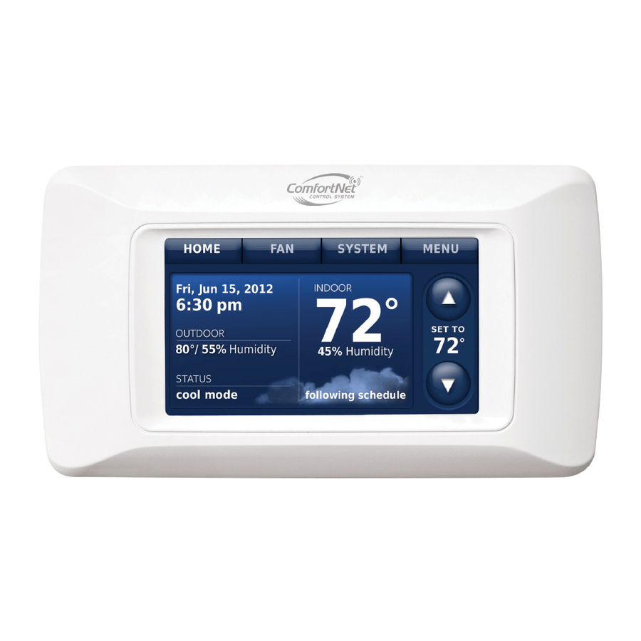
ComfortNet™ CTK04 Communicating Thermostat
With wireless accessories
Modulating control for up to 4 Heat/2 Cool communicating heat pump systems or up to
3 Heat/2 Cool communicating gas heat, electric cooling systems for residential and
commercial applications.
Installation guide for:
• ComfortNet CTK04
Communicating Thermostat
• Portable Comfort Control
• Wireless Outdoor Sensor
Quick start guide
1
2
Power optional accessories ................................................... 7
3
Setup thermostat ................................................................... 8
4
Link optional accessories ...................................................... 9
5
Mount optional accessories ................................................. 11
6
Installer options ................................................................... 12
ComfortNet™ User Menu .................................................... 13
Device replacement and specifications ..........................21-23
DISCONNECT POWER BEFORE INSTALLATION. Can cause electrical shock or equipment damage.
MERCURY NOTICE: If this product is replacing a control that contains mercury in a sealed tube, do not place the old control in
the trash. Contact the Thermostat Recycling Corporation at www.thermostat-recycle.org or 800-238-8192 for information on how and
where to properly and safely dispose of your old thermostat.
Must be installed by a trained, experienced technician. Read these instructions carefully. Failure to follow these
instructions can damage the product or cause a hazardous condition.
System
Installation
Guide
• Wireless Indoor Sensor
• RedLINK
Internet Gateway
™
• Entry/Exit Remote
• Vent Boost Remote
69-2688-07
I/O-CHTSTAT03
Advertisement
Table of Contents

Related Manuals for ComfortNET CTK04


Summary of Contents for ComfortNET CTK04
-
Page 1: Table Of Contents
System Installation Guide ComfortNet™ CTK04 Communicating Thermostat With wireless accessories Modulating control for up to 4 Heat/2 Cool communicating heat pump systems or up to 3 Heat/2 Cool communicating gas heat, electric cooling systems for residential and commercial applications. Installation guide for: • ComfortNet CTK04... -
Page 2: Usb Port
System Installation Guide The ComfortNet advantage The premium Honeywell ComfortNet™ control system is easy to use, energy- efficient, reliable and ensures the system is set up properly. Advanced operating algorithms built into the control delivers efficient equipment operation while providing optimal comfort. The Honeywell ComfortNet Communicating thermostat is designed to regulate and communicate with the central heating and cooling equipment and has the ability to share information so the user will enjoy efficient, economical comfort throughout the home. RedLINK™ Compatible RedLINK accessories include the Wireless Outdoor Sensor, Portable Comfort Control (PCC), RedLINK Internet Gateway, Wireless Indoor Sensor, TrueSTEAM™ humidifier with Wireless Adapter, Vent Boost Remote and Entry/Exit Remote. Customizable Service Reminders Set up to 10 service reminders. Choose from pre-set options or customize your own. Pre-set reminder options include filter replacement, humidifier maintenance, dehu- midifier filter, ventilator filter, UV bulb replacement, annual service, spring service, fall service and warranty expiring soon. Reminders based on the date or outdoor temperature will be displayed on the thermostat's main screen along with pre-set or custom instructions. User Interactions Log The interaction log stores history of thermostat setting changes including tempera- ture, system and installer setup. You can use the interaction log to save time by determining if the issue is a system error or an accidental user error. - Page 3 AIR CONDITIONER NEVER BE CONNECTED OR HEAT PUMP OR HEAT PUMP TO THE 24 VAC R&C NOTE: THE CTK04 CONTAINS THE THERMOSTAT, LITHIUM COIN CELL BATTERY, P/N F0430679005 POWER SUPPLY WALL MOUNTING SCREWS AND ANCHORS, SYSTEM INSTALLATION GUIDE, TERMINALS. OPERATING MANUAL, TRANSFORMER AND A WIRING SET THAT INCLUDES TWO TERMINAL BLOCKS AND WIRES.
-
Page 4: Install Thermostat
Thermostat Mounting Mount the thermostat approximately 5 feet from the floor on an interior wall using the included screws and anchors. Drill 3/16" holes for drywall and 7/32" holes for plaster. Do not install the thermostat where it can be affected by: • Drafts or dead spots behind doors and in corners. • Hot or cold air from ducts. • Radiant heat from sun or appliances. • Concealed pipes and chimneys. • Unheated (uncooled) areas such as an outside wall. Terminal Functions: 1 - Data 1 2 - Data 2 R - 24 volt power C - 24 volt common Wire Gauge: 18 gauge wire is recommended. Maximum wire distance between the ComfortNet thermostat and the IFC should not exceed 100 feet using 18 gauge wire. MCR29241 MCR33171 MCR33170 69-2688—07 I/O-CHTSTAT03... - Page 5 CTK04 ComfortNet™ Communicating Thermostat Install thermostat Wiring Thermostat, Indoor Unit and Outdoor Unit Wire Thermostat to Indoor Unit Connect 1, 2, R and C from the thermostat to 1, 2, R and C at the Indoor Unit. Wire Outdoor Unit Connect wires 1 and 2 from the Indoor Unit to 1 and 2 at the Outdoor Unit. Install the transformer provided and connect to R and C at the Outdoor Unit. (NOTE: installing the additional transformer is NOT required for inverter/variable speed outdoor com- municating units. Additional transformer IS required for 2-stage outdoor communicat- ing units.) Do NOT connect R and C between the Indoor Unit and Outdoor Unit. See below. INDOOR OUTDOOR BOARD TERMINAL BOARD TERMINAL CTK04 CONNECTIONS CONNECTIONS DATA 1 OUTDOOR...
- Page 6 System Installation Guide Power optional accessories [If no wireless accessories are used, skip to Section 3.] Outdoor air sensor Indoor air sensor Portable Comfort Control MCR32938 MCR32937 MCR32939 Install 2 fresh AA lithium batteries Install 2 fresh AAA alkaline batteries Install 3 fresh AA alkaline batteries RedLINK Internet Gateway...
-
Page 7: Power Optional Accessories
CTK04 ComfortNet™ Communicating Thermostat Power optional accessories TrueSTEAM Connect the ABCD terminals between TrueSTEAM and the THM4000 Wireless Adapter. Adjust the DIP Switches on TrueSTEAM as follows when using the Wireless Adapter: DIP3: UP DIP4: UP TrueSTEAM DIP5: DOWN THM4000R1000 MCR31476 Entry/Exit Remote or Vent Boost Remote 1 Remove the cover. 2 Insert the CR2450 coin cell battery (included) into the slot at the bottom of the remote. See polarity marking on the remote. 3 The LED will briefly flash green. If it flashes red, battery is not good. MCR33269 I/O-CHTSTAT03 69-2688—07... -
Page 8: Setup Thermostat
System Installation Guide Setup thermostat Initial Power Up 1 Turn on AC power to the system. 2 Select Language. Press Next. 3 Select Application (Residential or Commercial). Press Next. 4 Enter a Device Name. Press Next. The thermostat will automatically iden- tify the ComfortNet communicating equipment installed and then you will be prompted to add RedLINK accessories (page 9) and setup the Installer Options (page 12). 69-2688—07 I/O-CHTSTAT03... -
Page 9: Link Optional Accessories
CTK04 ComfortNet™ Communicating Thermostat Link optional accessories to wireless network If you need to return to the "Add Device" screen to add devices later, press MENU and scroll down to press INSTALLER OPTIONS. Enter the date code (password) when prompted. The date code is printed on the back of the thermostat; or press MENU > EQUIPMENT STATUS to find the date code. After you enter the password, scroll down to press WIRELESS DEVICE MANAGER and then select ADD DEVICE. While the Add Device screen is displayed on the thermostat, press and release the CONNECT button on each wireless device, as described below. Accessories need to be at least 2 feet away from the thermostat during the linking process. Press DONE after all devices have been linked... - Page 10 System Installation Guide Link optional accessories to wireless network Portable Comfort Control Press CONNECT on the Portable Comfort Control display screen. Press DONE when the screen displays "Connected." Press NO at the next screen to save and exit. (Or press YES to link another thermostat.) CONNECT Error messages:...
-
Page 11: Mount Optional Accessories
CTK04 ComfortNet™ Communicating Thermostat Mount optional accessories [If no sensors are used, skip to Section 6.] To install outdoor air sensor 1 Mount the sensor on a vertical exterior wall, at least 6 inches below any overhang. Choose a location protected from direct sunlight. 2 Place sensor securely in bracket, facing away from wall. M28491 To install indoor air sensor... -
Page 12: Installer Options
System Installation Guide Installer options (ISU) To setup the thermostat, press MENU and scroll down to press INSTALLER OPTIONS. Enter the date code (password) when prompted. The date code is printed on the back of the thermostat; or press MENU > EQUIPMENT STATUS to find the date code. After you enter the password, press CREATE SETUP to setup the thermostat. A brief summary of installer options follows. You can download a complete list of all options at http://customer.honeywell.com. Create Setup: Press CREATE SETUP to set all system settings one by one. View/Edit Current Setup: Press VIEW/EDIT CURRENT SETUP to select a specific function and make quick changes. -
Page 13: Comfortnet User Menu
CTK04 ComfortNet™ Communicating Thermostat Installer options (ISU) Function Function 4130 Entry/Exit Remote - 9100 High Humidity Comfort Reset Setting Away/Unoccupied Heat Setpoint 9180 Dehumidification Away Mode 4140 Entry/Exit Remote - 9190 Dehumidification Away Mode - Fan Control Vacation/Holiday Cool Setpoint... - Page 14 1. WIRE THERMOSTAT AND TrueSTEAM AS SHOWN. 2. SET THERMOSTAT ISU 8000 TO “STEAM”. 3. SET TrueSTEAM DIP SWITCHES AS SHOWN (3 DOWN, 4 UP, 5 DOWN). NOTE FAN INTERLOCK IS HANDLED BY THE COMFORTNET COMMUNICATION. TrueSTEAM DIP SWITCHES MCR33172 AFS MONITOR RECOMMENDED...
- Page 15 CTK04 ComfortNet™ Communicating Thermostat Heat pump with outdoor temperature lockouts Outdoor temperature lockouts are optional. See Installer Setup options (ISU 3120). Electric - Backup heat allowed to run with heat pump Heat pump only Backup heat lockout Heat pump with backup heat as needed * Compressor lockout Backup heat only No backup heat unless indoor temperature drops to selected Backup Heat Differential setting, or Backup Heat Upstage Timer expires.
-
Page 16: Normal Operation
System Installation Guide Basic and Advanced Temperature Control Options (ISU 3010) Basic Options: The Installer Setup displays basic temperature control options which include Backup Heat Differential, Backup Heat Upstage Timer and Outdoor Temperature Lockouts. Note: Outdoor Temperature Lockouts only apply to Heat Pump applications. Advanced Options: The Installer Setup displays both Basic and Advanced Options. Advanced temperature control options include Finish With High Cool Stage, Finish With High Heat Stage, Temperature Differential settings between all stages and Cycle Rate settings per stage. Finish With High Heat or Cool Stage - When a multi-stage heating or cooling system is used, this feature keeps the high stage of the heating or cooling equipment running until the desired setpoint is reached. - Page 17 CTK04 ComfortNet™ Communicating Thermostat Humidification The thermostat reads the indoor humidity level and allows the user to set a humidifi- cation setting with or without window protection. Window Protection Window Protection limits the amount of humidity to prevent frost or condensation on windows. Window Protection (ISU 8050) requires an outdoor sensor. The maximum humidity level that is allowed ("Window Limit") is displayed on the Humidification Settings screen. The thermostat prevents frost or condensation on windows by not allowing the humidity to go above the Window Limit when it is con- trolling the humidifier. This helps inform the user as to why their humidity setting might not be reached at times. The Window Limit is based on the current outdoor tempera- ture and the user's window protection setting. If Window Protection is turned Off, the ther- mostat controls the humidity level to the user's desired humidity setting. Frost or condensation may appear on windows. To see all humidification options, press MENU > INSTALLER OPTIONS > VIEW/EDIT CURRENT SETUP > HUMIDIFICATION. Dehumidification - Residential The thermostat reads the indoor humidity level and allows the user to set a dehu- midification setting.
- Page 18 System Installation Guide Dehumidification - Commercial The thermostat reads the indoor humidity level and allows the user to set a dehumidification setting. Dehumidification using the cooling system has the following methods of dehumidification control (ISU 9080): Basic: This option uses the cooling system to reach the desired humidity level. Minimum On Time and High Humidity Comfort Reset are not used with this method. This option should only be used if the equipment can lower the fan speed in a call for dehumidification. Minimum on Time (ISU 9090): This option ensures that the compressor runs long enough to effectively reduce humidity when the cooling equipment is cycled on. The compressor will run for the minimum "on time" you set until the desired humidity level is reached. High Humidity Comfort Reset (ISU 9100): This option uses the cooling system to lower the temperature up to 5 F below the current cool setpoint until the desired humidity is reached. The high humidity comfort range is from 1 to 5 F. High Humidity Comfort Reset with Minimum On Time (ISU 9090 and ISU 9100): This method uses both options above to reduce humidity while maintaining a comfortable temperature.
- Page 19 CTK04 ComfortNet™ Communicating Thermostat Dehumidification Away Mode Dehumidification Away Mode protects the home when unoccupied for long periods of time during hot and humid weather by maintaining the desired humidity and temperature settings. To start Dehumidification Away Mode, press Menu, then press Dehumidification Away Mode. The thermostat automatically follows settings that are set by the dealer during installer setup. Press Cancel to end Dehumidification Away Mode. Southern Dehumidification Away Mode Options: (ISU 9180 to 9200) • Fan: Auto, On or Circulate • Low Limit Temperature Setting: The thermostat allows the cooling system to lower the indoor air to the Low Limit Temperature Setting to control humidity. • Temperature Setting: The temperature maintained while Dehumidification Away Mode is active and the desired humidity level is satisfied.
- Page 20 System Installation Guide Indoor sensor operation Temperature control The thermostat can be set to respond to its internal temperature sensor, or to an optional remote indoor sensor. If multiple sensors are used, the thermostat will respond to an aver- age of temperatures detected at each sensor. Humidification control If optional remote indoor sensors are installed, you can choose which sensor you want to use for humidification control. You can use a differ- ent sensor for dehumidification. Dehumidification control If optional remote indoor sensors are installed, you can choose which sensor you want to use...
-
Page 21: Device Replacement And Specifications
CTK04 ComfortNet™ Communicating Thermostat Alerts Log MENU > INSTALLER OPTIONS > DATA LOGS > ALERTS LOG The thermostat saves the most recent 25 alerts. It records the date, time, alert status (snoozed, dismissed, recovered), and diagnostic information to help you identify and correct problems. User Interactions Log MENU > INSTALLER OPTIONS > DATA LOGS > USER INTERACTIONS LOG Check this log to find out if a problem was caused by an accidental user error. The log shows most changes made to thermostat settings, by time and date, and describes what change was made. The thermostat records the most recent 250 changes. You can quickly search them by date and time, or by function. This feature can be turned off if necessary, so that no user interactions are recorded. - Page 22 System Installation Guide Replacing system components To remove accessories from a thermostat At the thermostat 1 Press MENU and scroll down to press INSTALLER OPTIONS. Enter the date code (password) when prompted. The date code is printed on the back of the thermostat; or press MENU > EQUIPMENT STATUS to find the date code. 2 After you enter the password, scroll down to select WIRELESS DEVICE MANAGER. 3 Press REMOVE DEVICE, then select the device you want to remove. Specifications & replacement parts Operating Ambient Temperature Thermostat: 32 to 120° F (0 to 48.9° C) Portable Comfort Control: 32 to 120° F (0 to 48.9° C) Wireless Outdoor Sensor: -40 to 140° F (-40 to 60° C)
-
Page 23: Regulatory Information
CTK04 ComfortNet™ Communicating Thermostat Regulatory information FCC Compliance Statement (Part 15.19) (USA only) This device complies with Part 15 of the FCC Rules. Operation is subject to the following two conditions: This device may not cause harmful interference, and This device must accept any interference received, including interference that may cause undesired operation. - Page 24 Need Help? For assistance please visit www.ComfortNet1.com, or call toll-free: (888) 593-9988 Honeywell International Inc. Goodman Manufacturing Co., LP 1985 Douglas Drive North Suite 500 Golden Valley, MN 55422 5151 San Felipe http://customer.honeywell.com Houston, TX 77056 ® U.S. Registered Trademark. © 2014 Honeywell International Inc. 69-2688—07 M.S. Rev. 01-14 I/O-CHTSTAT03 Printed in U.S.A.
Need help?
Do you have a question about the CTK04 and is the answer not in the manual?
Questions and answers