Advertisement
Quick Links
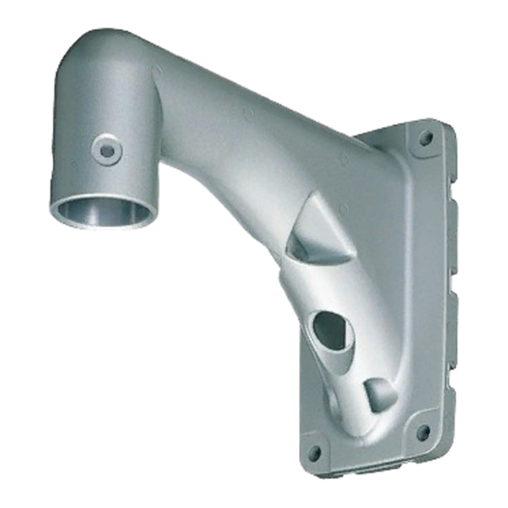
Wall Mount Bracket
Operating Instructions
WV-Q122E
Model No.
The camera in the illustration is separately sold.
Before attempting to connect or operate this product,
please read these instructions carefully and save this manual for future use.
The model number is abbreviated in some descriptions in this manual.
Advertisement

Related Manuals for Panasonic WV-Q122E


Summary of Contents for Panasonic WV-Q122E
-
Page 1: Operating Instructions
Wall Mount Bracket Operating Instructions WV-Q122E Model No. The camera in the illustration is separately sold. Before attempting to connect or operate this product, please read these instructions carefully and save this manual for future use. The model number is abbreviated in some descriptions in this manual. - Page 2 Precautions • Make sure that the place you are installing the camera is strong enough to support it. If it is not strong enough, then the cam- era may fall and hurt someone. • The following steps of installation and connection work should be done by qualified service personnel or system installers and should conform to all local codes.
- Page 3 5. Disassembly of Camera (1) Remove the upper base from the camera by loosening 3 screws. The screws that are removed need to be used during reassembly. Upper Base Be careful to not lose them. Turn the upper base and separate it. * Special screw (mounting screw): Use a hexa- gon wrench for the hexagon screw (M6).
- Page 4 (2) Be sure to hook the fall prevention wire to the bracket. Fall Prevention Wire (3) Fix the camera to the upper base. • Move the camera up so that its guide pins fit into the guide holes of the upper base. •...
- Page 5 Rear Cable Exit Mark hole positions 1. Preparations Specify the bracket fixing location, and then put in four anchor bolts (not supplied), or drill four bolt holes on the surface. Cable Access Hole Remember that a cable access hole is necessary on on the wall the wall in this case.
- Page 6 6. Disassembly of Camera (1) Remove the upper base from the camera by loosening 3 screws. The screws that are removed need to be used during reassembly. Be Upper Base careful to not lose them. Turn the upper base and separate it. * Special screw (mounting screw): Use a hexa- gon wrench for the hexagon screw (M6).
-
Page 7: Specifications
■ Dimensions Ø58 Fall Prevention Wire Hook Camera Fixing Screw Hole x4 4-Ø10 Ø25.4 Front Cable Exit Rear Cable Exit 111.5 (Punch out the hole when using) Unit: mm ■ Specifications Dimensions: 111.5(W) x 210.5(H) x 269(D) mm Weight: 2 kg approx. Weight and dimensions indicated are approximate. - Page 8 AM1105-2010 3TR004263CAA Printed in Japan...