Table of Contents
Advertisement
Quick Links
Advertisement
Table of Contents

Related Manuals for Audionet PRE1 G3


Summary of Contents for Audionet PRE1 G3
- Page 1 PRE1 G3 Stereo Pre-Amplifier User's Manual...
-
Page 3: Table Of Contents
Usage ............... 15 Powering up ................15 Switching on and off ..............15 Mains phase detection .............. 16 Using Audionet Link ..............16 Control elements on the front panel ........17 Volume control................17 Display ..................18 Input selection ................19 Muting .................. - Page 4 Set DC Servo for By-Pass M............ 33 7.12 Overview factory defaults ............34 Audionet Metal Remote Control ......35 Key assignment PRE1 G3 ............36 Changing the batteries ............. 36 Settings for Audionet preamplifier ......... 37 Technical information ..........39 Design ..................
-
Page 5: Preface
Preface The Audionet Team congratulates you on your purchase of this unit. But before you start listening to your new Audionet PRE1 G3, please read this manual carefully so you are able to use and enjoy all functions of this unit without drawback on music quality. -
Page 6: Included
· Always use the cloth bag to prevent scratches on the casing. · Please allow the PRE1 G3 to adapt to the climatic conditions in your listening room before you switch on the unit for the first time after transport. -
Page 7: Overview Front Panel
Overview front panel... -
Page 8: Overview Back Panel
Overview back panel... -
Page 9: Installation And Power Supply
Important · During connecting and removing of sources or amplifiers to the PRE1 G3 all units of your audio system have to be switched off to prevent damage of the PRE1 G3 or any of the other connected units. ·... -
Page 10: Orientation Of Mains Plug
· The PRE1 G3 is a Class I unit and must be earthed. Please ensure a stable earth connection. Phase ('hot' pin) is marked on the back panel ('phase') 21 . · If you connect the mains cord please make sure that mains switch 1 at the back panel is switched off. -
Page 11: Inputs And Outputs
5.1 Inputs The PRE1 G3 is equipped with 5 Cinch inputs 11 to 15 and one bal- anced (XLR) input 16 for connecting signal sources at line level. Addi- tionally, the monitor input 17 can used as another line level input. -
Page 12: Recording Devices
REC OUT 9 of the PRE1 G3. For playback please con- nect your recording devices only to input no. 5 IN 5 12 of the PRE1 G3. if they are also connected to the output REC OUT 9 of your PRE1 G3. -
Page 13: Audionet Link
You only need a simple optical 'Toslink' cable. Connect the 'Audionet Link' output OUT 1 18 or OUT 2 19 of your PRE1 G3 to the 'Audio- net Link' input of unit to be controlled. -
Page 14: Trigger Output
Use the power key on the front panel or the key PRE of the Audionet Metal Remote Control RC 1 or RC 2 to switch on the PRE1 G3. The PRE1 G3 is now ready to use and gets its power from the external power supply EPS / EPX. -
Page 15: Usage
'Installation and power supply' on page 9 and 'Inputs and outputs' on page 11). The PRE1 G3 is a stand-by unit. Please operate the mains switch 1 on the back panel. The display shows a welcome message for a brief mo- ment. -
Page 16: Mains Phase Detection
(e.g. power amplifiers, CD player or tuner) connected via 'Audionet Link' (also see section 'Audionet Link' on page 13). If the rest of your Audionet system is connected to your PRE1 G3 via 'Audionet Link', all linked units will be automatically switched on /off as soon as you switch on/off your PRE1 G3 using the power key on the front panel or the Audionet Metal Remote Control RC 1 or RC 2. -
Page 17: Control Elements On The Front Panel
The volume control of the PRE1 G3 runs in a range from –80 dB to +6 dB in real 1 dB steps relatively to the level of the input signal. Differ- ences in input levels can be adjusted for each input channel of the PRE1 G3 separately (see section 'Offset Adjust' on page 26. -
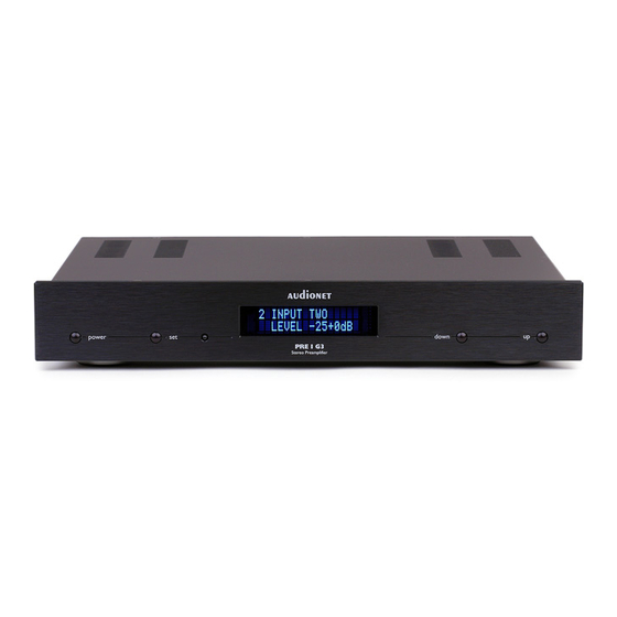
Page 18: Display
Display The display provides in the normal operating mode the following infor- mation: 5 INPUT FIVE LEVEL –46+0dB number of currently selected input channel, corresponds to the num- ber printed above the input jack on the back panel (see section 'Overview back panel' on page 8). -
Page 19: Input Selection
(for less than 2 seconds) to actually switch to the selected input channel. The PRE1 G3 features a 'soft' input selection. During the switching of inputs, first the volume is stepped down to –80 dB, followed by switching off the outputs. Now the input section switches to the new input channel. -
Page 20: Muting
Audionet Metal Remote Control RC 1 or RC 2 to mute or un-mute your PRE1 G3. Just as well as the input selection, the PRE1 G3 uses 'soft' muting, i.e. volume is stepped down gently to -80 dB, then the outputs are switched off. -
Page 21: Setup Menu
After the last menu item you will leave the setup menu automatically. Of course, you may leave the setup menu from each menu item by holding the set key down for longer than two seconds. The PRE1 G3 will return to the normal operating mode. -
Page 22: Set Monitor
Change any setting of a menu item by using the keys up and down on the front panel. Note · If you make no adjustments for longer than 12 seconds the PRE1 G3 will automatically leave the setup menu and return to normal operat- ing mode. ·... -
Page 23: Set Headphones
Headphones output HEADPHONES 4 is active, HP on & Link off but the 'Audionet Link' output OUT 2 19 is al- ways switched off. Use this option if you would like to switch off amplifiers, that are connected to the 'Audionet Link' output OUT 2 19 , automatically while you are using the headphones output. -
Page 24: Set Dim Level
· If you connect your power amplifier to the 'Audionet Link' output OUT 2 19 of the PRE1 G3, it will be switched off automatically as soon as you select the headphones option HP on & Link off. Thus, you are able to enjoy music with your headphones and need not to worry about the amplifier. -
Page 25: Balance Adjust
It switches off automatically several seconds af- ter the last user entry. · The PRE1 G3 activates the 'display saver' automatically after 10 minutes without any user entry. · During active 'display saver', the display shows only the number of the selected input channel and current volume level in the form of In 4 -47dB. -
Page 26: Offset Adjust
Use the down key to shift the balance to the left. The value in the display is now negative. The PRE1 G3 allows the user to shift the balance up to 9 dB to the left or the right in steps of 1 dB. -
Page 27: Set Dc Servo
For each of the six input channels and for the monitor loop of the PRE1 G3 you can define the adjustment of the input level in the range of –9 dB to +9 dB in steps of 1 dB to match the different output levels of sources connected to the PRE1 G3. -
Page 28: Channel Name
Note · In normal operating mode the display indicates an active DC Servo for the currently selected input channel by a symbol right beside the volume level in the 2 display line. Thus you can see at any time if the DC Servo is active: DC Servo is active 5 INPUT FIVE... -
Page 29: Set Out 2 (Sub)
· If the monitor loop is active, you are able only to edit the name of the monitor loop. You have to deactivate the monitor loop first, before you are able to edit the input channel names again. Set Out 2 (Sub) Press and hold the set key for longer than 2 seconds to enter the setup menu. -
Page 30: Set Autostart
The Autostart function is active. As soon as you connect active the PRE1 G3 to mains (i.e. use the mains switch 1 on the back panel) the unit starts up automatically to normal operating mode. Use this setting for timer controlled op- erations. - Page 31 MODE: - -). The By-Pass Mode was primarily intended to integrate the overwhelming sound quality of the PRE1 G3 into an existing home cinema setup or to expand an existing excellent stereophonic system based on the PRE1 G3 to a complete home cinema setup without missing out on the qualities of the PRE1 G3.
- Page 32 Mode in the setup menu item Set Channel for By-Pass Mode. The sig- nal at the input channel selected for By-Pass Mode operations is passed through the PRE1 G3 at a level of 0 dB (i.e. no change in volume level) to the outputs.
-
Page 33: Set Dc Servo For By-Pass M
The DC Servo for the By-Pass Mode is switched on. Activate the DC Servo only in cases where the source connected to the PRE1 G3 holds a high DC component in its output signal. The DC Servo eliminates the DC component. The input channel dedicated to the By- Pass mode is now AC-coupled. -
Page 34: Overview Factory Defaults
7.12 Overview factory defaults Option Setting SELECT INPUT INPUT TWO SET MONITOR disabled SET HEADPHONES HP off & Link on SET DIM LEVEL BALANCE ADJ. OFFSET ADJUST 0 dB (for all input channels) In 1-5: disabled SET DC SERVO In 6: active 1: BALANCED 2: INPUT TWO 3: INPUT THREE... -
Page 35: Audionet Metal Remote Control
Audionet Metal Remote Control The optional Audionet Metal Remote Control RC 1 or RC 2 controls all the important function of everyday use of your PRE1 G3. The following explains all these commands in detail. POWER < ä < •... -
Page 36: Key Assignment Pre1 G3
8.1 Key assignment PRE1 G3 Power key PRE use the key PRE to switch on / off your PRE1 G3. This key has the function as key power on the front panel. If the PRE1 G3 is in stand- by mode, press key PRE to switch on this unit. If the PRE1 G3 is al- ready switched on, then pressing PRE powers the unit down to stand- by mode. -
Page 37: Settings For Audionet Preamplifier
Settings for Audionet preamplifier The Audionet Metal Remote Control RC 1 or RC 2 has 6 keys to control an Audionet (pre-) amplifier like the PRE1 G3. The previous section 'Key assignment PRE1 G3' explains the function of these keys. - Page 38 For Audionet Metal Remote Control RC 2 the DIP switch for selecting the system address is located here: DIP switch for system address on RC 2 (the upper slider is for configuring a preamplifier) Put the DIP switch labelled 'SYS ADDRESS' in position '19' or '16' ac-...
-
Page 39: Technical Information
A microprocessor controls and monitors all functions. A two line, 16- digit display informs the user about all operating modes and makes it easy to adjust the PRE1 G3 to the user's preferences. The unit also fea- tures user-definable channel names and input level adjustment for each channel. -
Page 40: Security Advice
· During connecting or removing the PRE1 G3 to/from sources and/or power amplifiers all units have to be switched off to prevent damage of the PRE1 G3 or any of the other connected units. · Use dry cloth for cleaning! We would like to wish you many exciting listening experiences with your new Audionet product. -
Page 41: Technical Data
1 pair XLR balanced, gold plated 1 pair Cinch Rec Out, gold plated Outputs 1 pair Cinch Monitor, gold plated 2 Audionet Link, optical 1 connector, gold plated, for additional earth connection 1 trigger output, 12 Volts DC, 3.5mm telephone jack line and balanced out... - Page 42 Audionet Link outputs for remote control of other Audionet components (e.g. power amplifiers) selectable headphones output Audionet Metal Remote Control RC 1 or RC 2 Phono module for MM and MC pickups Options external precision power supply Audionet EPS or EPX Errors and omissions excepted.
Need help?
Do you have a question about the PRE1 G3 and is the answer not in the manual?
Questions and answers