GeoVision Surveillance system Installation Manual
Hide thumbs
Also See for Surveillance system:
- Quick start manual (131 pages) ,
- Quick start manual (111 pages)
Table of Contents
Advertisement
Quick Links
Advertisement
Table of Contents

Related Manuals for GeoVision Surveillance system


Summary of Contents for GeoVision Surveillance system
-
Page 2: Table Of Contents
Table of Contents Chapter 1 Video Capture Cards............1 GV-2004, 2008 .......................2 GV-1120, 1240, 1480 .....................8 GV-650, 800 ......................15 GV-600 .........................19 GV-250 .........................23 Installing Drivers ....................27 Connecting Hardware Watchdog................29 Comparison Chart....................30 Chapter 2 Hardware Accessories.............33 GV-Multi Quad Card .....................34 GV-Hybrid DVR Card....................37 GV-Loop Through Card ..................40 GV-DSP Card .......................43 GV-A16 Card ......................46... - Page 3 Chapter 3 Software Installation ............77 Before You Start ....................78 Installing the System.....................79 Program List ......................81 Chapter 4 Screen Overview ..............83 Main System ......................84 ViewLog ........................86 Remote Playback Client ..................90 SingleView MPEG4 Encoder Viewer ..............92 MultiView MPEG4 Encoder Viewer ..............93 Remote Playback on WebCam................95 Center V2......................96 Control Center Toolbar ..................98 Troubleshooting .................99...
-
Page 4: Chapter 1 Video Capture Cards
Chapter 1 Video Capture Cards This chapter includes the following information: • Minimum system requirements • Packing list • Connection diagrams • Specifications • Driver installation • Comparison chart... -
Page 5: Minimum System Requirements
1.1 GV-2004, 2008 The GV-2004 and GV-2008, as four-in-one combo cards, include the features of previous GV-Video Capture Card (recording of up to 16 video channels), GV-DSP Card (real-time display), GV-A16 Card (recording of up to 16 audio channels), and GV-Hybrid DVR Card (hardware compression). - Page 6 Video Capture Cards Connections (GV-2004) • Connect the D-Type video and audio cable to the GV-2004 Card. • Connect the TV Monitor to the GV-2004 Card if needed. 1-4 D-Type Video TV Monitor and Audio Cable Video 1~4 Audio 1~4 GV-2004 Card Figure 1-1 GV-2004 Card connections...
- Page 7 Connections (GV-2008) For the GV-2008 Card, you can choose to install one or two GV-2008 Cards to meet your different needs. Connect the D-Type video and audio cable to the GV-2008 Card. If needed, connect the TV monitor to the GV-2008 Card. When you install two GV-2008 Cards in a computer, you need to classify them as a master and a slave card.
- Page 8 Video Capture Cards Connecting Slave Card to Master Card • The card attached to the lower PCI slot number will act as Master, and the card attached to the higher PCI slot number will act as Slave. • Connect both cards’ inner pins with the 6-Pin Cable. See (A) connection in the Figure below.
- Page 9 Adjusting the Video Settings in the Main System One distinct feature of the GV-2004 and GV-2008 Cards is their ability of hardware compression, providing you with higher system performance and DVD recording quality. To take full advantage of the GV-2004 and GV-2008 Cards, you can adjust the video settings, including the codec, video resolution, frame rate, before running the GV-System.
-
Page 10: Specifications
Video Capture Cards 3. Use the drop-down list to select the camera for configuration. 4. In the fields of Video Resolution and Frame Rate Control, use the drop-down list to select your changes. If you want to apply the same settings to all selected cameras, click the finger button in each field. - Page 11 1.2 GV-1120, 1240, 1480 GV-1120, GV-1240 and GV-1480 are the three-in-one combo cards, providing one single card solution for 16 video / audio recording, real-time display and TV-out display. To meet different needs, there are three types of GV-Combo cards: D-Type, DVI Type and PCI-E.
- Page 12 Video Capture Cards Packing List (DVI Type) 1. GV-1120/1240/1480 Combo Card x 1 5. Software CD x 1 2. 1-16 DVI Video plus TV Out Cable x 1 Feature Guide x 1 3. 1-16 DVI Audio Cable x 1 Installation Guide x1 4.
- Page 13 Specifications (D-Type) GV-1120 GV-1240 GV-1480 Input Type DB15 x 2 (Video), DB9 x 2 (Audio) Video Input 8, 12, 16 Cams 8, 16 Cams 16 Cams Audio Input 8, 12, 16 Channels 8, 16 Channels 16 Channels TV Output RCA Connector x 1 NTSC 120 fps 240 fps...
- Page 14 Video Capture Cards Connections (PCI-E) • Plug the Audio Extension Card in the assigned connectors on the GV-Combo Card. • Connect D-Type video and audio cables to the GV-Combo Card and Audio Extension Card respectively. • Plug the power cable connector in the GV-Combo Card’s power connector. •...
- Page 15 Specifications (PCI-E) GV-1120 GV-1240 GV-1480 Input Type DB15 x 2 (Video), DB9 x 2 (Audio) Video Input 8, 12, 16 Cams 8, 16 Cams 16 Cams Audio Input 8, 12, 16 Channels 8, 16 Channels 16 Channels TV Output RCA Connector x 1 NTSC 120 fps 240 fps...
- Page 16 Video Capture Cards Connections (DVI Type) • Connect the DVI video and audio cables to the GV-Combo Card. • Connect the DVI TV Out cable to the TV monitor if needed. 1-16 DVI Video Cable TV Monitor DVI TV Out Cable GV-Combo Card 1-16 DVI Audio Cable Figure 1-8 GV-Combo Card (DVI Type) connections...
- Page 17 Specifications (DVI-Type) GV-1120 GV-1240 GV-1480 Input Type DVI x 1 (for Video), DVI x 1 (for Audio) Video Input 8, 12, 16 Cams 8, 16 Cams 16 Cams Audio Input 8, 12, 16 Channels 8, 16 Channels 16 Channels TV Output RCA Connector x 1 NTSC 120 fps...
- Page 18 Video Capture Cards 1.3 GV-650, 800 The GV-650 and GV-800 Card have the same appearance, system requirements and packing list so that we introduce both together in this section. However, you may choose between the two according to your need for recording rate and audio channels. Minimum System Requirements Windows 2000 / Windows XP / Windows Server 2003 Pentium 4-2.0 GHz...
- Page 19 Connections There are two types of GV-800 and GV-650 Cards: BNC and D-Type. BNC type only provides four video channels; video and audio extension cards are required for extension. D-Type can provide up to 16 video channels and four audio channels together. For the D-Type video capture card, plug the black video/audio cable into the black connector on the GV-650/800 Card;...
- Page 20 Video Capture Cards For the BNC-type video capture card, plug the Audio Extension Card into No. 1 or No. 2 connector on the GV-650/800 Card, as illustrated below. Both connectors are okay for connection. GV-800/650 Card Audio Extension Card Figure 1-10 BNC-type GV-650 or GV-800 Card connections...
- Page 21 Specifications GV-650 GV-800 BNC x 4 Input Type D-Type DB15 x 2 Video Input 4, 8, 12, 16 Cams Audio Input 2 Channels 4 Channels NTSC 60 fps 120 fps Recording Rate (At 320 x 240 Resolution) 50 fps 100 fps NTSC 60 fps 120 fps...
- Page 22 Video Capture Cards 1.4 GV-600 There are two types of GV-600 Cards: BNC and D-Type. BNC type only provides four video channels; video and audio extension cards are required for extension. D-Type can provide up to 16 video channels and one audio channel together. Minimum System Requirements Windows 2000 / Windows XP / Windows Server 2003 Pentium 4-2.0 GHz...
- Page 23 Connections For the D-Type video capture card, plug the black video/audio cable into the black connector on the GV-600 Card; the blue video cable into the blue connector, as illustrated below. Note: The GV-600 Card only supports one audio channel so that only one audio port can work in the supplied 1-8 Cams with 4-Port Audio D-Type cable.
- Page 24 Video Capture Cards For the BNC-Type video capture card, plug the Audio Extension Card into No. 1 or No. 2 connector on the GV-600 Card, as illustrated below. Both connectors are okay for connection. GV-600 Card Audio Extension Card Figure 1-12 BNC-type GV-600 Card connections...
- Page 25 Specifications GV-600 GV-600 BNC: BNC x 4 Input Type GV-600 D-Type: DB15 x 2 Video Input 4, 6, 8, 10, 12, 14, 16 Cams Audio Input 1 Channel NTSC 30 fps Recording Rate (At 320 x 240 Resolution) 25 fps NTSC 30 fps Display Rate...
- Page 26 Video Capture Cards 1.5 GV-250 There are two types of GV-250 Cards: BNC and D-Type. BNC type only provides four video channels; video and audio extension cards are required for extension. D-Type can provide up to 16 video channels and one audio channel together. Minimum System Requirements Windows 2000 / Windows XP / Windows Server 2003 Pentium 4-2.0 GHz...
- Page 27 Connections For the D-Type video capture card, plug the black video/audio cable into the black connector on the GV-250 Card; the blue video cable into the blue connector, as illustrated below. Note: The GV-250 Card only supports one audio channel so that only one audio port can work in the supplied 1-8 Cams with 4-Port Audio D-Type cable.
- Page 28 Video Capture Cards For the BNC-type video capture card, plug the Audio Extension Card into the connector on the GV-250 Card, as illustrated below. GV-250 Card Audio Extension Card Figure 1-14 BNC-type GV-250 Card connections...
- Page 29 Specifications GV-250 GV-250 BNC: BNC x 4 Input Type GV-250 D-Type: DB15 x 2 Video Input 1, 2, 4, 6, 8,12,16 Cams Audio Input 1 Channel NTSC 15 fps Recording Rate (At 320 x 240 Resolution) 12 fps NTSC 15 fps Display Rate 12 fps 720 x 480, 720 x 480 De-interlace,...
-
Page 30: Installing Drivers
Video Capture Cards 1.6 Installing Drivers After you install the GV-Video Capture Card on the computer, the Found New Hardware Wizard will automatically detect the device. Ignore the wizard and follow these steps to install drivers: 1. Insert the software CD. It will run automatically and pop up a window. 2. - Page 31 To verify the drivers are installed correctly, go to Device Manager and see if the following entries are listed. Expand the Sound, video and game controller field, you can see: Model Entry GV250 Audio GV-250 GV250 Video Capture GV600_4 or GV604(S) Video Capture #A GV-600-4 GV600_4 or GV604(S) Audio # A GV600V2, GV600V3 or GV600(S) Audio #A...
-
Page 32: Connecting Hardware Watchdog
1. Using the supplied jumper wire, connect the reset jumper pins on the card and on the motherboard. PC Reset Switch PWSW GeoVision GV-600v2 GV-600 v2 Motherboard Front Panel Jumper Figure 1-15 Watchdog connections 2. -
Page 33: Comparison Chart
1.8 Comparison Chart GV-250 GV-600 GV-650 GV-800 Input Type BNC / D-Type BNC / D-Type BNC / D-Type BNC / D-Type Video Input 1, 2, 4, 6, 8, 12, 16 4, 6, 8, 10, 12, 14, 16 4, 8, 12, 16 4, 8, 12, 16 NTSC 15 fps... - Page 34 Video Capture Cards GV-1120 GV-1240 GV-1480 GV-2004 GV-2008 GV-2008 x 2 D-Type / PCI-E / DVI-Type D-Type 8, 12, 16 8, 16 120 fps 240 fps 480 fps 120 fps 240 fps 480 fps 100 fps 200 fps 400 fps 100 fps 200 fps 400 fps...
-
Page 36: Chapter 2 Hardware Accessories
Chapter 2 Hardware Accessories This chapter includes the following information: • System requirements • Packing list • Connection diagrams • Specifications • Driver installation... -
Page 37: System Requirement
For further operations on GV-System, see “Quad Spot Monitors Controller”, Chapter 1, User’s Manual on the Surveillance System Software CD. System Requirement • Version 8.1 or above Packing List 1. - Page 38 Hardware Accessories Connections • Use the supplied Ribbon Cable to connect the GV-Multi Quad Card to the GV-Video Capture Card as illustrated below. • For the connection to the GV-2004 and GV-2008 Card, the supplied Ribbon Cable splits at one end with four 10-pin headers. Plug the corresponding cable headers into the connectors of GV-2004 or GV-2008 Card by the numbers marked on the headers and connectors.
- Page 39 Installing Drivers After you install the GV-Multi Quad Card to the computer, the Hardware Wizard will automatically detect the device. Ignore the wizard, and follow the steps in 1.5 Installing Drivers to install drivers. To verify the drivers are installed correctly, go to Device Manager. Expanding the Sound, video and game controllers field, you should see the entries for GVTVOUT Audio #A and GVTVOUT Video Capture #A.
-
Page 40: Gv-Hybrid Dvr Card
The GV-Hybrid DVR Card supported-channels do not work with the Pre-Rec Motion feature. For further operations on GV-System, see Configuring Hybrid Cameras, Chapter 1, User’s Manual on the Surveillance System Software CD. System Requirements • GV-600, 650, 750, 800, 1000, 1120, 1240 and 1480 Cards •... - Page 41 Connections Connect the GV-Hybrid DVR Card to the GV-Video Capture Card as illustrated below. Note: Make sure the Ribbon Cables are connected to the correct input and output on the GV-Hybrid DVR Card. 40-Pin Ribbon Cable Connects to the input of the 2 GV-Hybrid DVR Card or GV-DSP Card...
- Page 42 Hardware Accessories Installing Drivers After you install the GV-Hybrid DVR Card to the computer, the Hardware Wizard will automatically detect the device. Ignore the wizard, and follow the steps in 1.5 Installing Drivers, Chapter 1 to install drivers. To verify the drivers are installed correctly, go to Device Manager. In the DVR-Devices field, you should see 4 entries for GVMP2 and 11 entries for GVMP2 Null, as shown below.
-
Page 43: Gv-Loop Through Card
2.3 GV-Loop Through Card The GV-Loop Through Card is designed to take the video signal directly from the GV- Video Capture Card, without internal device processes, and then split it into 16 signals while maintaining video quality. With the duplicate 16 signals, the card can meet your need for multiple monitors. - Page 44 Hardware Accessories Connections • Connect D-type cables and the GV-Video Capture Card to the GV-Loop Through Card as illustrated below. • For the connection to the GV-2004 and GV-2008 Card, the supplied Ribbon Cable splits at one end with four 10-pin headers. Plug the corresponding cable headers into the connectors of GV-2004 or GV-2008 Card by the numbers marked on the headers and connectors.
- Page 45 Specifications Interface for GV-Video Capture Card 40-Pin Connector x 2 DB15 Connector x 2 Output Interface 40-Pin Connector x 1 Input Signal 16 Channels Dimensions 130 mm x 98 mm...
-
Page 46: Gv-Dsp Card
TV output, allowing for the simultaneous display on computer and a TV monitor (spot monitor). For further operations on GV-System, see DSP Spot Monitor Controller, Chapter 1, User’s Manual on the Surveillance System Software CD. System Requirements •... - Page 47 Connections Use the supplied Ribbon Cable to connect the GV-DSP Card to the GV-Video Capture Card as illustrated below. GV Video Capture Card 40-Pin Ribbon Cable TV Monitor GV-DSP Card Figure 2-7 GV-DSP Card connections...
- Page 48 Hardware Accessories Installing Drivers After you install the GV-DSP Card to the computer, the Hardware Wizard will automatically detect the device. Ignore the wizard, and follow the steps in 1.5 Installing Drivers to install drivers. To verify the drivers are installed correctly, go to Device Manager. Expanding the Sound, video and game controllers field, you can see: Figure 2-8 Verifying GV-DSP 16-port Card drivers Model...
-
Page 49: Gv-A16 Card
2.5 GV-A16 Card The GV-A16 Card can work with the GV-Video Capture Card to record audio for 16 channels, and to provide full duplex audio communication between local and remote users. Packing List 1. GV-A16 Card x 1 3. 9-16 D-Type Audio Cable x 1 2. - Page 50 Hardware Accessories Installing Drivers After you install the GV-A16 Card to the computer, the Hardware Wizard will automatically detect the device. Ignore the wizard, and follow the steps in 1.5 Installing Drivers, Chapter 1 to install drivers. To verify the drivers are installed correctly, go to Device Manager. Expanding the Sound, video and game controllers field, you should see the entries for GVA16 Audio and GVA16 Video.
-
Page 51: Gv-Net Card
2.6 GV-NET Card The GV-NET Card is a RS-485 to RS-232 interface converter. This Card connects to the RS-232 port on your computer, and allows RS-485 devices, such as PTZ domes, to be connected through the Card. Packing List 1. GV-NET Card x 1 3. - Page 52 Hardware Accessories RS-485 Device Connections Following provides three examples of connecting RS-485 devices to your computer through the GV-NET Card. Connecting PTZ Domes The GV-NET Card can connect up to 16 PTZ domes. RS-485+ RS-485- PTZ Dome 1 PTZ Dome 2 PTZ Dome 16 Figure 2-12 Connecting PTZ domes Connecting the POS System...
- Page 53 DI 8 DO 4-2 DO 5-2 DO 6-2 RS-485- DO 7-2 DI 1 RS-485+ DO 8-2 DI 2 GeoVision GV-IO DO 1-1 DO 2-1 DI 3 DO 3-1 DO 4-1 DI 4 DO 5-1 DO 6-1 Module 1 DI 5...
-
Page 54: Gv-Net/Io Card
Hardware Accessories 2.7 GV-NET/IO Card The GV-NET/IO Card not only is a RS-485 / RS-232 interface converter, but also supports four digital inputs and four relay outputs, meeting your need for external alarms and sensors. Packing List 1. GV-NET/IO Card x 1 2. - Page 55 Connections • Use the Ribbon Cable to connect the GV-NET/IO Card to the GV-Video Capture Card. • Use the RJ-11 to DB9 Cable to connect the GV-NET/IO Card to the PC’s COM port. • Use the 4-Pin Mini Power Cable to connect the GV-NET/IO Card to the PC’s power supply.
- Page 56 Hardware Accessories Connecting Output Devices Out 1 Out 4 FIRE Electronic Door Locks Alarms Figure 2-16 Connecting output devices Connecting Input Devices IN 1 IN 4 Magnetic Contact Motion Sensors Dry Contact Wet Contact Figure 2-17 Connecting input devices Connecting RS-485 Devices The connections of RS-485 devices to the GV-NET/IO Card are the same as the GV-NET Card.
- Page 57 Specifications Input Input Signal 5V DC (Floating) / TTL Input High State Low State Relay Output Relay Status Normal Open Output Relay Capacitance 2A / 30V DC; 0.25A / 250V AC Relay On/Off Time 4ms / 4ms RS-232 Interface RJ-11 to DB9 Cable Communication RS-485, 1,200-19,200 bps DC IN...
-
Page 58: Gv-Io 12-In Card
Hardware Accessories 2.8 GV-IO 12-In Card The GV-IO 12-In Card is designed to work with the GV-NET/IO Card. With 12 digital inputs, the GV-IO 12-In Card can expand the GV-System’s capacity up to 16 digital inputs. System Requirements • GV-NET/IO Card Packing List 1. - Page 59 Connections Use the four-connector Ribbon Cable to connect the GV-IO 12-In Card, GV-Video Capture Card, GV-NET/IO Card and GV-IO 12-Out Card together, as illustrated below. 20-Pin Ribbon Cable GV Video Capture Card Input 5 Input 6 Input 7 Input 8 Input 9 Input 10 Input 11...
- Page 60 Hardware Accessories Note: 1. Use the switch for Dry Contact and 5V Wet Contact. 2. The GV-IO 12-In Card accepts either all dry-contact or all wet-contact devices. Don’t mix two type devices in the same card. (Default: Dry Contact) 3. To prevent noise interference in I/O operation, tightly screw the GV-IO 12-In Card to the computer case.
-
Page 61: Gv-Io 12-Out Card
2.9 GV-IO 12-Out Card The GV-IO 12-Out Card is designed to work with the GV-NET/IO Card. With 12 replay outputs, the GV-IO 12-Out Card can expand the GV-System’s capacity up to 16 relay outputs. System Requirements • GV-NET/IO Card Packing List 1. - Page 62 Hardware Accessories Connections Use the four-connector Ribbon Cable to connect the GV-IO 12-Out Card, GV- Video Capture Card, GV-NET/IO Card and GV-IO 12-In Card together, as illustrated below. 20-Pin Ribbon Cable Relay Out 5 Relay Out 6 GV Video Capture Card Relay Out 7 Relay Out 8 Relay Out 9...
- Page 63 Specifications Relay Output Relay Status Normal Open Output 2A / 30V DC; Relay Capacitance 0.25A / 250V AC Relay On/Off Time 4ms / 4ms DC IN DC 5V, 1A Environmental Condition 0~50 Degree C, 5%~95% (Non-Condensing) GV-600 V3, GV-650 V3, GV-800 V3, GV-900 V1.11, Compatible Model GV-1000 V1.21, GV-1120, GV-1240, GV-1480, GV-2004 and GV-2008...
-
Page 64: Gv-Net Box
Hardware Accessories 2.10 GV-NET Box The GV-Net Box is a RS-485 / RS-232 interface converter, the same function as the GV- Net Card. The differences are that the GV-NET Card is fixed within the computer and receives the power supply from your computer, while the GV-NET Box is an independent box and has its own power supply adaptor. - Page 65 Specifications RS-232 to PC DB9 Male to DB9 Female Cable RS-485 Interface Two Wires Communication RS-485, 1,200-19,200 bps DC IN Power Adapter DC 5V, IA Inner Positive Environmental Condition 0 to 50 Degree C, 5%-95% (Non-Condensing) Compatible Model All GV-Video Capture Card Models Dimensions 103 (W) x 32 (H) x 64 (D) mm...
-
Page 66: Gv-Io And Gv-Relay Module
Hardware Accessories 2.11 GV-IO and GV-Relay Module The GV-IO and GV-Relay module includes one GV-IO Box and two GV-Relay Boxes, providing eight digital inputs and 16 relay outputs. The GV-IO and GV-Relay modules connect to the GV-System through the RS-232 / RS- 485 interface converter, including GV-NET Card, GV-NET/IO Card and GV-NET Box. - Page 67 Connections This illustration uses the GV-NET Box to bridge computer and the GV-IO Box. Instead, you can use the GV-NET Card or the GV-NET I/O Card as the bridge. GV-NET Box RS-232 to PC RS-485 RS-232 RS-485+ RS-485- GV-IO GV-RELAY GV-RELAY Input Devices 1-8 Output Devices 1~16...
- Page 68 Hardware Accessories Specifications GV-IO Box Input Input Signal 0-5V DC (Floating) Input High State Low State Wiring Label GND, DI 1~ DI 8 Output Output Circuit TTL Open Collect Output +5V-1, DO 1-1~DO 8-1 Wiring Label +5V-2, DO 1-2~DO 8-2 Communication RS-485, 9600 bps DC IN...
-
Page 69: Gv-Hub Box
3. DB9 RS-232 Cable (1.8 meters) x 4 Overview RS-485-C G RS-485-D - LEDs RS-485-C + RS-485-D + RS-232-C RS-485-D G RS-485-C - RS-232-D LEDs GeoVision GV-HUB LEDs RS-232-A LEDs RS-485-B - RS-485-A G RS-485-B + RS-485-A + RS-232-B RS-485-B G RS-485-A - Figure 2-22 GV-Hub DIP Switches To change the DIP switches, you must open the GV-Hub Box. - Page 70 DO 1-2 DI 7 DO 2-2 DO 3-2 DI 8 DO 4-2 DO 5-2 DO 6-2 DO 7-2 DO 8-2 GeoVision GV-IO PTZ Dome 1 GV-IO Box PTZ Dome 2 GeoVision GV-HUB PTZ Dome 16 GV-System Figure 2-24 Connecting RS-485 devices...
- Page 71 Installing Drivers When you connect the GV-Hub Box to the computer, the Found New Hardware Wizard will automatically detect the device. Ignore the wizard, and follow these steps to install the drivers. 1. Insert the installation CD to your computer. 2.
- Page 72 Hardware Accessories Specifications Signal: DCD, RxD, TxD, DTR, GND, DSR, RTS, CTS RS-232 Connecter: 4 x DB9 Male (A, B, C, D) Serial Interface Signal: D+, D-, GND RS-485 Connector: 4 x Terminal Block (A, B, C, D) Serial Line Protection 16 KV ESD for All Signals USB 1.1, 1.0 Compliance...
-
Page 73: Gv-Com Box
2. A to B USB Cable (1.2 meters) x 1 5. Installation CD x 1 3. DB9 RS-232 Cable (1.8 meters) x 1 6. Installation Guide x1 Overview GeoVision GV-COM RS-232 RS-485 - RXD TXD PWR RS-485 + Figure 2-27 GV-COM... - Page 74 The diagram below illustrates how to use Terminal Resistor on Terminal Block attached to the RS-485 device: RS-485- RS-485- Terminal Resistor GeoVision GV-COM GeoVision GV-DATA CAPTURE RS-485+ RS-485+ GV-COM PTZ, GV-Data Capture, etc. Figure 2-28 Terminal Resistor connections Installing Drivers When you coonect GV-COM to the computer, the Found New Hardware Wizard will automatically detect the device.
- Page 75 Specifications Signal: DCD, RxD, TxD, DTR, GND, DSR, RTS, CTS RS-232 Connecter: DB9 Male Serial Interface Signal: D+, D- RS-485 Connector: Terminal Block Serial Line 16 KV ESD for All Signals Protection USB 1.1, 1.0 Compliance USB 2.0 Backward Compatible Speed Full speed 12 Mbps Parity...
-
Page 76: Gv-Data Capture V2 Box
Hardware Accessories 2.14 GV-Data Capture V2 Box The GV-Data Catpure V2 can integrate your POS system (cash register) with the GV- System. Through the intergration, you can investigate a transaction with transaction data overlaying on video footage. System Requirements • Version 6.0.2.0 or above For details on GV-Data Capture V2 Box, see GV-Data Capture V2 User’s Manual attached with the product. -
Page 77: Gv-Keyboard
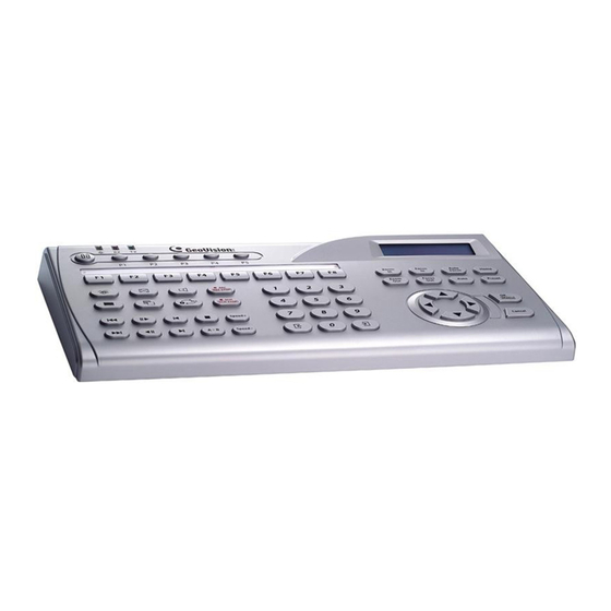
System Requirements • GV-Data Capture V3: GV-System version 6.0.2.0 or above • GV-Data Capture V3E: GV-System version 8.0.4.0 or above For details on GV-Data Capture V3 Series, see GV-Data Capture V3 Series User’s Manual attached with the product. 2.17 GV-Keyboard The GV-Keyboard is designed to program and operate GV-Systems. -
Page 78: Gv-Wiegand Catpure Box
IP cameras do. With the GV-Video Server attached to analog cameras, you can see camera images through a web browser anywhere and anytime. With the GV- Video Server connected to the GV-System, your existing surveillance system can be upgraded and networked into a new IP surveillance system. -
Page 80: Chapter 3 Software Installation
Chapter 3 Software Installation This chapter includes the following information: • Important notice • Installing a program • Program list... -
Page 81: Before You Start
3.1 Before You Start For optimal performance of your system, it is important to follow these recommendations before installing the system software: • It is strongly recommended to divide your hard disk into two partitions. One partition is for installing Windows OS and System Software, and the other for storing audio/video files and system logs. -
Page 82: Software Installation
Software Installation 3.2 Installing the System When you insert the Surveillance System Software CD, the Install Program window will pop up automatically: Figure 3-1 The Install Program Window Before installing the system software, make sure DirectX 9.0c is already installed on your computer. - Page 83 1. In the Install Program window, click Install GeoVision xxx System (ex. Install GeoVision V8.1.0.0 System). 2. To install the Main System, select GeoVision Main System, and follow the on-screen instructions. 3. Follow the above steps to install other programs one by one.
-
Page 84: Program List
Software Installation 3.3 Program List The Surveillance System Software CD includes the following programs: First Page: Main System Remote View IP Multicast Center V2 Fast Backup and Restore Multicam System LocalDDNS Server Authentication Server Dynamic DNS Service Remote Playback Client site Figure 3-2 First page of program installation 10. -
Page 86: Chapter 4 Screen Overview
Chapter 4 Screen Overview The GV-System provides two skin types: Silver and Conventional. The factory default is Silver. Each skin type has its own interface design. Therefore, this chapter gives you an overview of the following major screens: • Main System •... -
Page 87: Main System
4.1 Main System Silver Conventional... -
Page 88: Screen Overview
Screen Overview The controls in the main screen: No Name Description Indicates the camera number matching the port number in the GV Camera Number video capture card. Camera Name Indicates the given camera name. Date/Time Indicates the current date and time. Storage Space Indicates the remaining disk space. -
Page 89: Viewlog
4.2 ViewLog Silver Conventional... - Page 90 Screen Overview The controls in the ViewLog window: No Name Description Camera Name Indicates the given camera name. Camera View Displays the playback video. Date Tree Displays date folders. Video Event List Displays video events within a certain date folder. View Mode Sets screen divisions: Single, Thumbnail, Quad or Multi View.
- Page 91 Silver Functional Panel The controls in the Functional Panel: No Name Description Adds effects to the images. The effect options include: Sample, Contrast/Brightness, Light Enhancement, Effects Equalization, Sharpen, Smooth, Grayscale, Copy, Undo to Prev. Action and Undo All Effects. Save As AVI Saves a video file as avi or exe format.
- Page 92 Screen Overview Conventional Functional Panel The controls in the Function Panel: No Name Description Gives the examples of “Before” and “After” effects of contrast, Sample brightness, light enhancement, equalization, sharpness, smoothness and Gray. Contrast/Brightness Modifies color contrast and brightness of the video image. Light Enhancement/ Modifies light enhancement and equalization of the video image.
-
Page 93: Remote Playback Client
4.3 Remote Playback Client Silver Conventional... - Page 94 Screen Overview The controls in the RPB Client window: Name Description Camera Name Indicates the given camera name. Camera View Displays the playback video. Connect Sets the connection to the RPB servers. Disconnect Closes all or selected connections to the RPB servers. Download (Play) Downloads and plays the remote video.
-
Page 95: Singleview Mpeg4 Encoder Viewer
4.4 SingleView MPEG4 Encoder Viewer The controls in the SingleView Viewer: No Name Description Brings up these options: Alarm Notify, Data Rate Configure, Change Server Remote Config, Change Server, Show Camera Name and Enalbe DirectDraw. Change Camera Sets the desired camera for display. PTZ Control Displays the PTZ control panel. -
Page 96: Multiview Mpeg4 Encoder Viewer
Screen Overview 4.5 MultiView MPEG4 Encoder Viewer 14 13 The controls in the MultiView Viewer: No Name Description Monitoring Window Displays live video. Host Server Window Displays connected GV-Systems and their available cameras. UPnP Device Displays all hosts on the same LAN. PTZ Control Displays the PTZ control panel. - Page 97 Add/Remove Channel Adds or deletes the channels for video polling. Click the Add or Remove Channel button and then click the desired channel to add to or remove from the video polling. Full Screen Switches to a full screen view. Video Polling Rotates through the selected channels.
-
Page 98: Remote Playback On Webcam
Screen Overview 4.6 Remote Playback on WebCam The controls in the Remote Playback on WebCam: No Name Description File Tree Displays date folders. Event List Displays the video events Channel Select Tab Selects different channels. Option Includes the Enable DirectDraw option. Object Search Searches Object Index. -
Page 99: Center V2
4.7 Center V2 Silver Conventional... - Page 100 Screen Overview The controls in the Center V2 window: No Name Description Monitoring Window Displays live video. Indicates the date, time, remaining disk space and the total Status Panel number of online channels versus available channels. Type the desired ID in the Current Subscriber field and click this Find A Subscriber button to search.
-
Page 101: Control Center Toolbar
4.8 Control Center Toolbar Silver Conventional The controls on the Control Center Toolbar: Name Description Host List Opens the Host List to create and edit DVRs. Group List Opens the Group List to group cameras from different DVRs. Opens the Edit toolbar to display these buttons: Edit Search DVR, Configure, Save, and Delete. -
Page 102: Troubleshooting
Troubleshooting... - Page 103 GV-System is designed to provide you with trouble-free performance. If it does not appear to be functioning correctly, please make sure all connectors are properly attached and follow these troubleshooting steps: GV-System has video and/or audio lost. If your GV-System fails to show video, audio or both, try these steps: 1.
- Page 104 Panel”, in Chapter 1, User’s Manual, Software CD. 2. If multiple PTZ cameras are installed, make sure to activate each PTZ camera individually. How can I find more help? 1. Visit our website at http://www.geovision.com.tw/english/4_1.asp 2. Write us at support@geovision.com.tw...
Need help?
Do you have a question about the Surveillance system and is the answer not in the manual?
Questions and answers