d&b audiotechnik D12 Hardware Manual
Hide thumbs
Also See for D12:
- Software manual (36 pages) ,
- Hardware manual (32 pages) ,
- Manual (36 pages)
Table of Contents
Advertisement
Quick Links
Advertisement
Table of Contents

Related Manuals for d&b audiotechnik D12


Summary of Contents for d&b audiotechnik D12
- Page 1 D12 Amplifier Hardware manual (2.0E)
- Page 2 Please refer to the information in the operating manual. WARNING! Dangerous voltage! General Information D12 Amplifier Hardware manual Version (2.0E), 08/2004, D2012.E.02 © by d&b audiotechnik AG 2004; all rights reserved. The information contained in this manual has been carefully checked for accuracy, at the time of going to press, however no guarantee is given with respect to the correctness.
-
Page 3: Table Of Contents
Contents 1. Safety precautions............5 1.1. Information regarding use of the D12 Amplifier.......5 2. Introduction..............7 2.1. Scope of supply..................7 3. D12 Amplifier..............8 3.1. D12 based systems..................8 3.2. D12 block diagram..................8 3.3. Digital signal processing................9 3.4. D12 power amplifiers................10 3.5. SenseDrive....................10 3.6. Power supply.....................11 3.6.1. - Page 4 7.2. Technical drawings..................28 8. EU declaration of conformity (CE symbol)....29 8.1. EU conformity D12..................29 Index...................30 Figures used in the manual................30 Tables used in the manual................30 D12 Amplifier, Hardware manual (2.0E) Contents - 2...
-
Page 5: Safety Precautions
The following information is intended to prevent fires and possible electric shocks: The D12 is a protective class 1 unit. Make sure that the earth (ground) contact is attached when the unit is in operation. A missing earth (ground) contact may lead to dangerous voltages in the housing and controls. - Page 6 Damage to the unit is unlikely, but cannot be excluded. To meet the EMC requirements, use only shielded cables with properly connected plugs for all input signal terminals. D12 Amplifier, Hardware manual (2.0E) Safety precautions - 2/Page 6 of 32...
-
Page 7: Introduction
This manual describes the facilities and functions of the hardware of the d&b D12 amplifier. A detailed description of the D12 Software and remote control is given in the D12 Amplifier Software manual, which is also provided with the D12 Amplifier. -
Page 8: D12 Amplifier
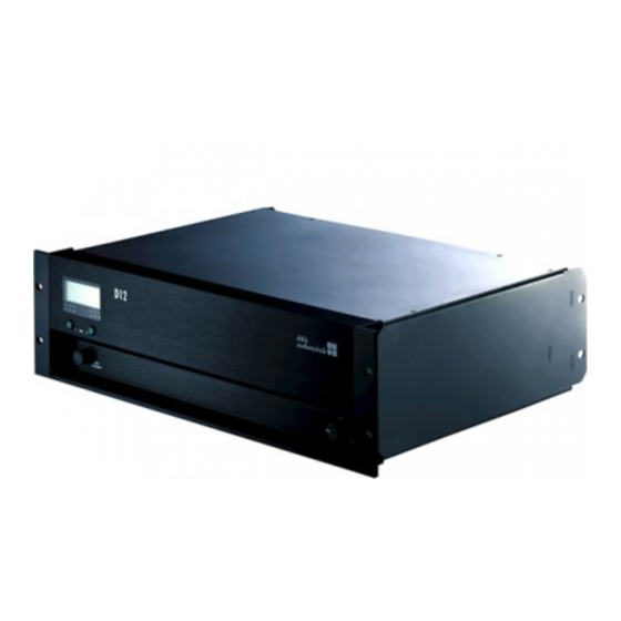
REMOTE and SERVICE interface, all connectors and status indicators. The D12 is housed in a 19" x 353 mm (13.9") 3 rack unit enclosure made from stainless steel with an extruded aluminium front panel. -
Page 9: Digital Signal Processing
0.3 msec. into the signal path. If two identical loudspeakers are driven by different controllers the respective delays of the units used have to be considered (D12 = 0.3 msec., E-PAC = 1.0 msec. and A1/P1200A no delay). The D12 effectively positions its respective loudspeaker at a distance of 24 cm (0.79 ft) in front of a loudspeaker driven by the E-PAC... -
Page 10: D12 Power Amplifiers
3.4. D12 power amplifiers The two power amplifiers fitted to the D12 can deliver 2 x 750 W continuous sine wave power into an 8 ohms load, increasing to 2 x 1200 W continuous sine wave power into a 4 ohms load. These maximum output ratings measured with sine wave are valid for minutes only until the unit will switch into thermal protect. -
Page 11: Power Supply
265 - 400 V Overvoltage Tab. 2: Voltage ranges 115/230 V To prevent the D12 from cycling on and off with fluctuating mains power supply voltages, the switching thresholds are delayed and about 4% apart from the border of the voltage range (hysteresis). -
Page 12: Inrush Current Limiter
The fan speed is consequently reduced during quieter passages preventing background noise interference. If the D12 heats up a "Temp. Warning" is given out and the fan will give full cooling power permanently. For further information please refer to section 6.1. Installation on page 3.8. -
Page 13: Controls And Indicators
The power consumption is very low (2 W typical). POWER - ON: the D12 is switched on. Via remote or the MUTE A or B switchl the D12 can be switched to standby mode. To indicate standby mode the display remains active. -
Page 14: Level/Push Menu (Digital Rotary Encoder) [3]
D12 may also be powered back on by remote control from standby mode. IMPORTANT! When the D12 is set to STANDBY (or the mains power is turned off) the movement of the loudspeaker cones in the cabinets connected is no longer damped by the power amplifier output. This removal of the damping makes them susceptible to excitation by other loudspeakers in the surroundings. -
Page 15: Indicators
The display is illuminated and can be set to "on/off/timeout 10s." A detailed description of the menu structure and access is given in the D12 Software manual, which is also provided with the D12. [5][6][7] [5][6][7] CH A CH B Fig. -
Page 16: Ovl Led (A/B) - Overload (Red) [7]
4.2.4. OVL LED (A/B) - Overload (red) [7]: - Illuminates depending on the input signal ⇒ Overload: either the input signal level is too high or the D12 is trying to deliver too high an output current. If in doubt reduce the input gain at the D12 level control. -
Page 17: Connections
Only use a fuse of the correct type and nominal current value. Before restoring power to the D12 all cabling should be checked for faults. If in any doubt disconnect all signal and loudspeaker connections. The mains fuses are located above the PowerCon socket and fullfill a purely protective function in case of a device fault. -
Page 18: Remote [10]
5.1.3. REMOTE [10] 1..8 1..8 Pin 1 n.c. The D12 is fitted with a 2-wire serial remote control interface, (2 x RJ 45) Pin 2 n.c. carrying both the RIB and CAN-Bus signals. All pins of both connectors Pin 3 n.c. -
Page 19: Connector Panel (I/O Panel)
We strongly recomend the use of standard AES/EBU cable with a characteristic impedance of 110 ohms. 5.1.8. OUT A/B [15 (a/b)] The D12 amplifier is supplied with EP5 or NL4 output connectors. OUT A OUT A The pin assignment for the loudspeaker output connectors is... -
Page 20: Dual Channel Mode
SUB TOP or SUB cabinets independently. selected In "Dual channel mode" the D12 acts as an two channel amplifier – stereo amplifier - the amplifier channels are connected to their OUT B respective output connectors (AMP Ch A to OUT A and AMP Ch B to... -
Page 21: Pin Assignments/Pin Equivalents
These pin assignments allow full range cabinets and subwoofers to be linked together and connected to the amplifier in mixed configuration (Mix-TOP/SUB) using a single 4 or 5-wire cable. SenseDrive is only available when using 5-wire cables. D12 Amplifier, Hardware manual (2.0E) Page 21 of 32... -
Page 22: D12 I/O Modes
5.3. D12 I/O modes (Default input routing) Fig. 18: D12 I/O Configurations D12 Amplifier, Hardware manual (2.0E) Page 22 of 32... -
Page 23: Installation And Operation
This advice is particularly important if amplifiers are being racked up for touring use. IMPORTANT! Since the D12 amplifier can generate a lot of heat, please ensure, whatever the mounting or racking arrangement, that adequate cool airflow is provided to avoid a build-up of hot air inside the rack leading to overheating. -
Page 24: Operation
The table gives power figures for various types of signal waveforms. They were measured on a D12 driving a 4 ohm load (both channels) to the clipping point of both channels using a sine wave burst signal of 24 dBu with a variable duty cycle. -
Page 25: Operating Conditions
When using the D12 at its upper temperature limit of 45°C (113°F), the maximum continous output power is 500 watts total or 250 watts per channel. Again referring to section 6.2.1 - (Tab. 7) - the unit will work properly with e.g. -
Page 26: Technical Documentation
Sampling...................48 kHz / 96 kHz / 2 Ch/n Synchronisation........Word-Sync: PLL-locked to source (slave mode) OUT A/B........................EP5 / NL4 dependent on the loudspeaker input version or type REMOTE....................2 x RJ 45 parallel SERVICE.......................D-SUB-9 female D12 Amplifier, Hardware manual (2.0E) Page 26 of 32... - Page 27 **reduced output power or short term operation Humidity (rel.), average....................70 % Dimensions and weight Height x width x depth..............3 RU x 19" x 353 mm .........................3 RU x 19" x 13.9 " Weight......................13 kg / 28.7 lb D12 Amplifier, Hardware manual (2.0E) Page 27 of 32...
-
Page 28: Technical Drawings
MUTE LEVEL POWER PUSH MENU 483 [19.00"] 338 [13.31"] 443 [17.44"] 5 [0.20" ] Fig. 23: D12 enclosure dimensions in mm [inch] OUT A LINK INPUT OUT A LINK INPUT C AU TION R ISK O F ELECT RIC SHOCK... -
Page 29: Eu Declaration Of Conformity (Ce Symbol)
AG consisting of the amplifier unit. - D12, Z2600.000/001 - D12, Z2600.300/301 All products of type D12 starting from variant Z2600.000 are included, provided they correspond to the original technical version and have not been subject to any later design or electromechanical modifications. -
Page 30: Index
Figures used in the manual Fig.# Titel Page Fig. 1: D12 Amplifier..............8 Fig. 15: D12 Input/Output routing Dual channel mode Fig. 2: D12 amplifier block diagram........8 with standard input routing............20 Fig. 3: D12 Controls and indicators........13 Fig. 16: D12 Input/Output routing Mix TOP/SUB mode Fig. - Page 32 d&b audiotechnik AG, Eugen-Adolff-Str. 134, D-71522 Backnang, Germany, Phone +49-7191-9669-0, Fax +49-7191-95 00 00_______...
Need help?
Do you have a question about the D12 and is the answer not in the manual?
Questions and answers