Table of Contents
Advertisement
Quick Links
Advertisement
Table of Contents

Related Manuals for VIA Technologies EPIA-M910


Summary of Contents for VIA Technologies EPIA-M910
- Page 1 USER MANUAL EPIA-M910 Mini-ITX embedded board 1.02-06252012-100000...
-
Page 2: Regulatory Compliance
The information and product specifications within this document are subject to change at any time, without notice and without obligation to notify any person of such change. VIA Technologies, Inc. reserves the right the make changes to the products described in this manual at any time without prior notice. -
Page 3: Safety Precautions
Battery Recycling and Disposal Only use the appropriate battery specified for this product. Do not re-use, recharge, or reheat an old battery. Do not attempt to force open the battery. Do not discard used batteries with regular trash. Discard used batteries according to local regulations. Safety Precautions Always read the safety instructions carefully. - Page 4 M910 M910 User Manual User Manual Box Contents and Ordering Information Model Number CPU Frequency Description EPIA-M910-16 1.6GHz Nano™ X2 Standard kit 1 x SATA cable 1 x I/O bracket EPIA-M910-16P 1.6GHz Nano™ X2 Standard kit 1 x SATA cable...
-
Page 5: Table Of Contents
EPIA EPIA- - - - M910 M910 User Manual User Manual EPIA EPIA M910 M910 User Manual User Manual Table of Contents 1. 1. 1. 1. Product Overview Product Overview ........ Product Overview Product Overview .................................................... - Page 6 EPIA EPIA- - - - M910 M910 User Manual User Manual EPIA EPIA M910 M910 User Manual User Manual 2.2.11. SATA Connectors ................. 32 2.2.12. USB 2.0 Pin Headers................33 2.2.13. COM Pin Header for COM3~COM8 ..........34 2.2.14. PS/2 Keyboard and Mouse Pin Header ..........35 2.2.15.
- Page 7 EPIA EPIA- - - - M910 M910 User Manual User Manual EPIA EPIA M910 M910 User Manual User Manual 6. 6. 6. 6. BIOS Setup Utility ........ BIOS Setup Utility ................................61 BIOS Setup Utility BIOS Setup Utility ........
- Page 8 ..........................95 95 A.1. EPIA-M910-16 ..................... 95 A.1.1. Playing DVD – Power DVD 5.0 ............... 95 A.1.2. Playing MP3-Media Player ................ 96 A.1.3. Running Network Application ..............96 A.1.4. IDLE........................ 97 A.1.5. RUN Burn-in Test ..................97 A.1.6.
- Page 9 M910 User Manual User Manual A.3.8. EuP/ErP Enable S3 ..................108 A.3.9. EuP/ErP Enable Power OFF..............108 A.4. EPIA-M910-10PE ....................109 A.4.1. Playing DVD – Power DVD 5.0 .............109 A.4.2. Playing MP3 – Media Player ..............109 A.4.3. Running Network Application ...............110 A.4.4. IDLE......................110 A.4.5.
- Page 10 User Manual Lists of Figures Figure 1: Layout diagram of the EPIA-M910 mainboard (top view) ...... 7 Figure 2: Mounting holes and dimensions of the EPIA-M910 mainboard.... 9 Figure 3: External I/O port dimensions of the EPIA-M910 mainboard ....10 Figure 4: Height distribution of the EPIA-M910 mainboard (for EPIA-M910-16, EPIA-M910-16P, EPIA-M910-12Q &...
- Page 11 EPIA EPIA- - - - M910 M910 User Manual User Manual EPIA EPIA M910 M910 User Manual User Manual Figure 30: SPI pin header ....................38 Figure 31: LPC pin header....................39 Figure 32: CLEAR CMOS jumper ................. 40 Figure 33: SATA DOM voltage select jumper............42 Figure 34: COM1 and COM2 voltage select jumper ..........
- Page 12 EPIA EPIA- - - - M910 M910 User Manual User Manual EPIA EPIA M910 M910 User Manual User Manual Figure 63: Illustration of Boot Settings Configuration..........81 Figure 64: Illustration of Security Settings screen............ 83 Figure 65: Illustration of Advanced Chipset Settings screen......... 85 Figure 66: Illustration of North Bridge VIA VX900 Configuration screen ..
- Page 13 EPIA EPIA- - - - M910 M910 User Manual User Manual EPIA EPIA M910 M910 User Manual User Manual Lists of Tables Table 1: PS/2 port pinout ....................14 Table 2: VGA port pinout ..................... 15 Table 3: COM port pinout .................... 16 Table 4: Gigabit Ethernet port pinout ................
- Page 14 EPIA EPIA- - - - M910 M910 User Manual User Manual EPIA EPIA M910 M910 User Manual User Manual Table 32: COM5 and COM6 voltage select jumper settings ....... 45 Table 33: COM7 and COM8 voltage select jumper settings ....... 46 Table 34: LVDS jumper settings...................
-
Page 15: Product Overview Product Overview
Technology Suite, and VIA TwinTurbo technology. The VIA EPIA-M910 has two 1066 MHz DDR3 DIMM slots that support up to 8 GB memory size. The VIA EPIA-M910 provides support for high fidelity audio with its included VIA VT2021 High Definition Audio Codec. In addition it supports two SATA 3Gb/s storage devices. -
Page 16: Key Features And Benefits
EPIA EPIA- - - - M910 M910 User Manual User Manual EPIA EPIA M910 M910 User Manual User Manual 1.1. Key Features and Benefits ™ ™ 1.1.1. VIA Nano X2 / Eden X2 Processor/VIA QuadCore The VIA Nano X2 / Eden X2 is a dual-core processor and 64-bit superscalar x86 processor based on a 40 nanometer process technology. -
Page 17: Via Vx900 Msp Chipset
EPIA-M910 obtain the maximum benefits from its past investments in PCI expansion cards. The VIA EPIA-M910 also includes a 1-Lane PCI Express 2.0 expansion slot that provides protection against obsolescence. The VIA EPIA-M910 further proves its versatility with its included Mini PCI Express slot. -
Page 18: Product Specifications
EPIA EPIA- - - - M910 M910 User Manual User Manual EPIA EPIA M910 M910 User Manual User Manual 1.2. Product Specifications Processor Processor Processor Processor VIA Nano™ X2 1.6GHz with heatsink and fan VIA Eden™ X2 1.0GHz with heatsink ... - Page 19 EPIA EPIA- - - - M910 M910 User Manual User Manual EPIA EPIA M910 M910 User Manual User Manual 1 x Front audio pin header 1 x PS/2 keyboard/mouse pin header 6 x RS232 pin headers (powered with selectable 5V/12V) ...
- Page 20 EPIA EPIA- - - - M910 M910 User Manual User Manual EPIA EPIA M910 M910 User Manual User Manual System Monitoring & Management System Monitoring & Management System Monitoring & Management System Monitoring & Management Wake-on-LAN Keyboard Power-on Timer Power-on ...
-
Page 21: Layout Diagram
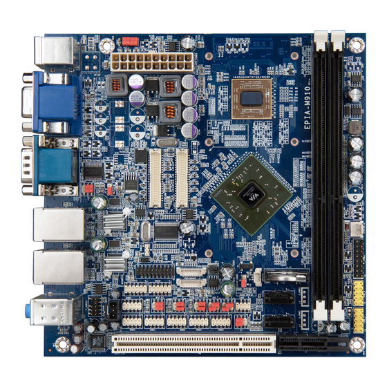
EPIA EPIA- - - - M910 M910 User Manual User Manual EPIA EPIA M910 M910 User Manual User Manual 1.3. Layout Diagram Figure Figure 1 1 1 1 : Layout diagram of the : Layout diagram of the EPIA EPIA- - - - M M M M 91 910 0 0 0 mainb mainboard oard (top view) - Page 22 EPIA EPIA- - - - M910 M910 User Manual User Manual EPIA EPIA M910 M910 User Manual User Manual Memory slots (DIMM1, DIMM2) AT/ATX mode select jumper (J6) LVDS connectors (LVDS1, LVDS2) COM voltage selector jumper for external COM1 and COM2 (J10) SMBus pin header (SMBUS1) LPC pin header (LPC1) LVDS inverter connectors (INVERTER1, INVERTER2)
-
Page 23: Product Dimensions
EPIA EPIA- - - - M910 M910 User Manual User Manual EPIA EPIA M910 M910 User Manual User Manual 1.4. Product Dimensions Unit: mm Figure Figure Figure Figure 2 2 2 2 : Mounting holes and dimensions of the : Mounting holes and dimensions of the : Mounting holes and dimensions of the : Mounting holes and dimensions of the EPIA EPIA... - Page 24 EPIA EPIA- - - - M910 M910 User Manual User Manual EPIA EPIA M910 M910 User Manual User Manual Unit: mm Figure Figure 3 3 3 3 : : : : External External I/O I/O port port dimensions of the dimensions of the EPIA EPIA- - - - M910 M910 mainboard...
-
Page 25: Height Distribution
EPIA EPIA- - - - M910 M910 User Manual User Manual EPIA EPIA M910 M910 User Manual User Manual 1.5. Height Distribution Height: 33 Height: 33 Height: 33 Height: 33 Height: 3 Height: 32.4 Height: 3 Height: 34.6 Height: 3 Height: 3 Height: 3 Height: 3... - Page 26 EPIA EPIA- - - - M910 M910 User Manual User Manual EPIA EPIA M910 M910 User Manual User Manual Height: 33 Height: 33 Height: 35 5 5 5 Height: 3 Height: 3 Height: 34.6 Height: 33 Height: 33 Height: 3 Height: 3 Height: 3 Height: 3...
-
Page 27: I/O Interface
2. 2. 2. 2. I/O Interface I/O Interface I/O Interface I/O Interface The VIA EPIA-M910 has a wide selection of interfaces integrated into the board. It includes a selection of frequently used ports as part of the external I/O coastline. 2.1. External I/O Ports... -
Page 28: Ps/2 Port
EPIA EPIA- - - - M910 M910 User Manual User Manual EPIA EPIA M910 M910 User Manual User Manual 2.1.1. PS/2 Port The mainboard has two integrated PS/2 ports for keyboard and mouse. Each port is using the 6-pin Mini-DIN connector. The color purple is used for a PS/2 keyboard while the color green is used for a PS/2 mouse. -
Page 29: Vga Port
EPIA EPIA- - - - M910 M910 User Manual User Manual EPIA EPIA M910 M910 User Manual User Manual 2.1.2. VGA Port The integrated 15-pin VGA port uses a female DE-15 connector. The VGA port is for connecting to analog displays. The pinout of the VGA port is shown below. -
Page 30: Com Port
EPIA EPIA- - - - M910 M910 User Manual User Manual EPIA EPIA M910 M910 User Manual User Manual 2.1.3. COM Port The integrated 9-pin COM port uses a male DE-9 connector. The COM (COM1) port supports the RS-232 standard. The pinout of the COM port is shown below. -
Page 31: Rj45 Lan Port: Gigabit Ethernet
EPIA EPIA- - - - M910 M910 User Manual User Manual EPIA EPIA M910 M910 User Manual User Manual 2.1.4. RJ45 LAN port: Gigabit Ethernet The integrated 8-pin Gigabit Ethernet port is using an 8 Position 8 Contact (8P8C) receptacle connector (commonly referred to as RJ45). The pinout of the Gigabit Ethernet port is shown below. -
Page 32: Audio Ports
EPIA EPIA- - - - M910 M910 User Manual User Manual EPIA EPIA M910 M910 User Manual User Manual 2.1.5. Audio Ports There are three audio jack receptacles integrated into a single stack on the I/O coastline. Each receptacle can fit a 3.5 mm Tip Ring Sleeve (TRS) connector to enable connections to Line-in, Line-out, and MIC-in. -
Page 33: Hdmi Port
EPIA EPIA- - - - M910 M910 User Manual User Manual EPIA EPIA M910 M910 User Manual User Manual 2.1.6. HDMI Port The integrated 19-pin HDMI port uses an HDMI Type A receptacle connector as defined in the HDMI 1.2 specification. The HDMI (High Definition Multimedia Interface) port is for connecting the high definition video and digital audio. -
Page 34: Usb 2.0 Port
User Manual 2.1.7. USB 2.0 Port There are two integrated USB 2.0 ports in EPIA-M910 mainboard. The USB- interface port gives complete Plug and Play and hot swap capability for external devices and it complies with USB UHCI, rev. 2.0. Each USB port is using the USB Type A receptacle connector. -
Page 35: Onboard Connectors
EPIA EPIA- - - - M910 M910 User Manual User Manual EPIA EPIA M910 M910 User Manual User Manual 2.2. Onboard Connectors 2.2.1. ATX Power Connector The mainboard has a 20-pin ATX power connector onboard. The ATX power connector is labeled as “ATX_POWER1”. The pinout of the ATX power connector is shown below. -
Page 36: Lvds Panel Connectors
EPIA EPIA- - - - M910 M910 User Manual User Manual EPIA EPIA M910 M910 User Manual User Manual 2.2.2. LVDS panel connectors The mainboard has two LVDS panel connectors: LVDS1 and LVDS2. LVDS1 connector is controlled by VIA VX900 chipset while the LVDS2 connector is controlled by VT1636 LVDS transmitter. - Page 37 EPIA EPIA- - - - M910 M910 User Manual User Manual EPIA EPIA M910 M910 User Manual User Manual +LD1C1 -LD1C2 + LD1C2 -LCLK1 + LCLK1 -LD1C3 + LD1C3 DVP1_SPCLK DVP1_SPD Table Table Table Table 10 10 10 10: LVDS1 : LVDS1 : LVDS1 panel pinout : LVDS1...
-
Page 38: Lvds Inverter Connector
EPIA EPIA- - - - M910 M910 User Manual User Manual EPIA EPIA M910 M910 User Manual User Manual 2.2.3. LVDS Inverter Connector The mainboard has two inverters for controlling the LVDS panel backlight and brightness. INVERTER1 corresponds to the LVDS1 panel connector. INVERTER2 corresponds to the LVDS2 panel connector. -
Page 39: Digital I/O Pin Headers
EPIA EPIA- - - - M910 M910 User Manual User Manual EPIA EPIA M910 M910 User Manual User Manual 2.2.4. Digital I/O pin headers The mainboard includes two Digital I/O pin headers that support eight GPO and eight GPI pins. Figure Figure 17 17: Digital I/O pin headers... -
Page 40: Dc-In Power Connector
EPIA EPIA- - - - M910 M910 User Manual User Manual EPIA EPIA M910 M910 User Manual User Manual 2.2.5. DC-in Power Connector For the DC version of the mainboard, there is a DC-in power connecter in addition to the DC-in coaxial power connector. This enables two methods for delivering +12V to the mainboard. -
Page 41: Sata Power Connector
EPIA EPIA- - - - M910 M910 User Manual User Manual EPIA EPIA M910 M910 User Manual User Manual 2.2.6. SATA Power Connector For the DC version of the mainboard, there are two built-in SATA power connectors. These connectors are required to power SATA hard drives. The SATA power connectors are labeled as “S_PWR1”... -
Page 42: Cmos Battery Slot
EPIA EPIA- - - - M910 M910 User Manual User Manual EPIA EPIA M910 M910 User Manual User Manual 2.2.7. CMOS Battery Slot The mainboard is equipped with a CMOS battery slot, which is compatible with CR2032 coin batteries. The CMOS battery slot is labeled as “BAT2”. When inserting a CR2032 coin battery, be sure that the positive side is facing the locking clip. -
Page 43: Front Panel Pin Header
EPIA EPIA- - - - M910 M910 User Manual User Manual EPIA EPIA M910 M910 User Manual User Manual 2.2.8. Front Panel Pin Header The front panel pin header consists of 15 pins in a 16-pin block. Pin 15 is keyed. -
Page 44: Smbus Pin Header
EPIA EPIA- - - - M910 M910 User Manual User Manual EPIA EPIA M910 M910 User Manual User Manual 2.2.9. SMBus Pin Header The SMBus pin header consists of three pins that allow connecting the SMBus devices. Devices communicate with a SMBus host and/or other SMBus devices using the SMBus interface. -
Page 45: Cpu And System Fan Connectors
EPIA EPIA- - - - M910 M910 User Manual User Manual EPIA EPIA M910 M910 User Manual User Manual 2.2.10. CPU and System Fan Connectors There are two fan connectors on board: one for the CPU and one for the chassis. -
Page 46: Sata Connectors
EPIA EPIA- - - - M910 M910 User Manual User Manual EPIA EPIA M910 M910 User Manual User Manual 2.2.11. SATA Connectors The two SATA connectors on board can support up to 3 Gb/s transfer speeds. The SATA connectors are labeled as “SATA1” and “SATA2”. The pinout of the SATA connectors are shown below. -
Page 47: Usb 2.0 Pin Headers
EPIA EPIA- - - - M910 M910 User Manual User Manual EPIA EPIA M910 M910 User Manual User Manual 2.2.12. USB 2.0 Pin Headers The mainboard has three USB 2.0 pin header blocks that support up to six USB 2.0 ports. The pin header blocks are labeled as “USB_2”, USB_3, and “USB_4”. The pinout of the USB pin headers are shown below. -
Page 48: Com Pin Header For Com3~Com8
EPIA EPIA- - - - M910 M910 User Manual User Manual EPIA EPIA M910 M910 User Manual User Manual 2.2.13. COM Pin Header for COM3~COM8 There are a total of three COM pin headers on the mainboard. Each COM pin header supports the RS-232 standard. -
Page 49: Ps/2 Keyboard And Mouse Pin Header
EPIA EPIA- - - - M910 M910 User Manual User Manual EPIA EPIA M910 M910 User Manual User Manual 2.2.14. PS/2 Keyboard and Mouse Pin Header The mainboard has a pin header for a PS/2 keyboard and mouse. The pin header is labeled as “KBMS1”. -
Page 50: Front Audio Pin Header
EPIA EPIA- - - - M910 M910 User Manual User Manual EPIA EPIA M910 M910 User Manual User Manual 2.2.15. Front Audio Pin Header In addition to the TRS audio jacks on the external I/O coastline, the mainboard has a pin header for Line-Out and MIC-In. The pin header is labeled as “F_AUDIO1”. -
Page 51: Spdif Connector
EPIA EPIA- - - - M910 M910 User Manual User Manual EPIA EPIA M910 M910 User Manual User Manual 2.2.16. SPDIF Connector The mainboard has one 3-pin SPDIF (Sony Philips Digital Interface) connector. The SPDIF output provides digital audio to external speakers or compressed AC3 data to an external Dolby Digital Decoder. -
Page 52: Spi Pin Header
EPIA EPIA- - - - M910 M910 User Manual User Manual EPIA EPIA M910 M910 User Manual User Manual 2.2.17. SPI Pin Header The mainboard has one 8-pin SPI pin header. The SPI (Serial Peripheral Interface) pin-header is used to connect to the SPI BIOS programming fixture. The pin header is labeled as “SPI1”. -
Page 53: Lpc Pin Header
EPIA EPIA- - - - M910 M910 User Manual User Manual EPIA EPIA M910 M910 User Manual User Manual 2.2.18. LPC Pin Header The mainboard has one LPC pin header for connecting LPC devices. The pin header is labeled as “LPC”. The pinout of the pin header is shown below. Figure Figure 31 31: LPC pin header... -
Page 54: Jumpers
EPIA EPIA- - - - M910 M910 User Manual User Manual EPIA EPIA M910 M910 User Manual User Manual 3. 3. 3. 3. Jumpers Jumpers Jumpers Jumpers 3.1. Clear CMOS Jumper The onboard CMOS RAM stores system configuration data and has an onboard battery power supply. - Page 55 EPIA EPIA- - - - M910 M910 User Manual User Manual EPIA EPIA M910 M910 User Manual User Manual Note: Note: Note: Note: Except when clearing the RTC RAM, never remove the cap from the CLEAR_CMOS jumper default position. Removing the cap will cause system boot failure. Avoid clearing the CMOS while the system is on;...
-
Page 56: Sata Dom Power Select Jumper
EPIA EPIA- - - - M910 M910 User Manual User Manual EPIA EPIA M910 M910 User Manual User Manual 3.2. SATA DOM Power Select Jumper The SATA connectors can be used to support Disk-on-Module flash drives. The power for SATA DOM is controlled by the jumper labeled as “J1”.When the jumpers are set, +5V will be delivered to the 7 pin of the SATA connectors. -
Page 57: Com1 And Com2 Voltage Select Jumper
EPIA EPIA- - - - M910 M910 User Manual User Manual EPIA EPIA M910 M910 User Manual User Manual 3.3. COM1 and COM2 Voltage Select Jumper The voltage for COM1 and COM2 is controlled by the jumper labeled as “J10”. The voltage can be either +5V or +12V. +5V is the default setting. The odd pin numbers correspond to COM1. -
Page 58: Com3 And Com4 Voltage Select Jumper
EPIA EPIA- - - - M910 M910 User Manual User Manual EPIA EPIA M910 M910 User Manual User Manual 3.4. COM3 and COM4 Voltage Select Jumper The voltage for COM3 and COM4 is controlled by the jumper labeled as “J13”. The voltage can be either +5V or +12V. +5V is the default setting. The odd pin numbers correspond to COM3. -
Page 59: Com5 And Com6 Voltage Select Jumper
EPIA EPIA- - - - M910 M910 User Manual User Manual EPIA EPIA M910 M910 User Manual User Manual 3.5. COM5 and COM6 Voltage Select Jumper The voltage for COM5 and COM6 is controlled by the jumper labeled as “J14”. The voltage can be either +5V or +12V. +5V is the default setting. The odd pin numbers correspond to COM5. -
Page 60: Com7 And Com8 Voltage Select Jumper
EPIA EPIA- - - - M910 M910 User Manual User Manual EPIA EPIA M910 M910 User Manual User Manual 3.6. COM7 and COM8 Voltage Select Jumper The voltage for COM7 and COM8 is controlled by the jumper labeled as “J15”. The voltage can be either +5V or +12V. +5V is the default setting. The odd pin numbers correspond to COM7. -
Page 61: Lvds Jumper Settings
EPIA EPIA- - - - M910 M910 User Manual User Manual EPIA EPIA M910 M910 User Manual User Manual 3.7. LVDS Jumper Settings The LVDS connectors and LVDS inverters can operate on different input voltages. The mainboard has one jumper (J12) that controls the voltage delivered to the LVDS1 panel connector and input voltage delivered to the INVERTER1 connector. -
Page 62: At/Atx Mode Jumper (1-2: Atx/2-3:At)
EPIA EPIA- - - - M910 M910 User Manual User Manual EPIA EPIA M910 M910 User Manual User Manual 3.8. AT/ATX Mode Jumper (1-2: ATX/2-3:AT) The AT/ATX jumper enables the user to specify AT or ATX power mode support. To enable support for +3.3V, the jumper must be set to ATX mode. Figure Figure 39 39: : : : AT/ATX mode jumper... -
Page 63: Jatx_On Mode Jumper
EPIA EPIA- - - - M910 M910 User Manual User Manual EPIA EPIA M910 M910 User Manual User Manual 3.9. JATX_on Mode Jumper The JATX_on jumper enables the user to boot AT mode without battery. Figure Figure 40 40: JATX_on : JATX_on mode jumper mode jumper Figure... -
Page 65: Expansion Slots
EPIA EPIA- - - - M910 M910 User Manual User Manual EPIA EPIA M910 M910 User Manual User Manual 4. 4. 4. 4. Expansion Slots Expansion Slots Expansion Slots Expansion Slots 4.1. DDR3 Memory Slots The mainboard provide one DDR3 DIMM memory slot. The memory slot can accommodate up to 4 GB of 1066 MHz memory. -
Page 66: Installing A Memory Module
EPIA EPIA- - - - M910 M910 User Manual User Manual EPIA EPIA M910 M910 User Manual User Manual 4.1.1. Installing a Memory Module Step 1 Step 1 Step 1 Step 1 Disengage the locking mechanism at both ends of the DIMM slot by pressing the retaining clips outward. - Page 67 EPIA EPIA- - - - M910 M910 User Manual User Manual EPIA EPIA M910 M910 User Manual User Manual Step Step 3 3 3 3 Step Step Insert the DIMM memory module into the slot and push down at both ends until the locking clips lock the DIMM memory module into place.
-
Page 68: Removing A Memory Module
EPIA EPIA- - - - M910 M910 User Manual User Manual EPIA EPIA M910 M910 User Manual User Manual 4.1.2. Removing a Memory Module Step 1 Step 1 Step 1 Step 1 To disengage the locking clips, push outward the locking clips on both ends of memory slot. -
Page 69: Pci Slot
EPIA EPIA- - - - M910 M910 User Manual User Manual EPIA EPIA M910 M910 User Manual User Manual 4.1.3. PCI Slot The onboard PCI slot, labeled as “PCI_SLOT1”, supports 5V 32-bit PCI cards. It is not compatible with PCI cards requiring 3.3V signaling. The location of the PCI slot is shown below. -
Page 70: Pci Express Slot
EPIA EPIA- - - - M910 M910 User Manual User Manual EPIA EPIA M910 M910 User Manual User Manual 4.1.4. PCI Express Slot The onboard PCI Express slot is located adjacent to the PCI slot. The PCI Express slot provides support for 1-lane cards. Due to the orientation of the slot, a riser card module must be used. -
Page 71: Hardware Installation Hardware Installation
Hardware Installation 5.1. Installing into a Chassis The EPIA-M910 can be fitted into any chassis that has the mounting holes for compatible with the standard Mini-ITX mounting hole locations. Additionally, the chassis must meet the minimum height requirements for specified areas of the mainboard. -
Page 72: Suggested Minimum Chassis Height
EPIA EPIA- - - - M910 M910 User Manual User Manual EPIA EPIA M910 M910 User Manual User Manual Each side of the mainboard should have a buffer zone from the internal wall of the chassis. The side of the mainboard that accommodates the I/O coastline should have a buffer of 1.00 mm. -
Page 73: Suggested Keepout Areas
EPIA EPIA- - - - M910 M910 User Manual User Manual EPIA EPIA M910 M910 User Manual User Manual 5.1.3. Suggested keepout areas The figure below shows the areas of the mainboard that is highly suggested to leave unobstructed. Figure Figure 50 50: Suggested keepout areas : Suggested keepout areas... -
Page 75: Bios Setup Utility
EPIA EPIA- - - - M910 M910 User Manual User Manual EPIA EPIA M910 M910 User Manual User Manual 6. 6. 6. 6. BIOS Setup Utility BIOS Setup Utility BIOS Setup Utility BIOS Setup Utility 6.1. Entering the BIOS Setup Utility Power on the computer and press Delete Delete during the beginning of the boot Delete... -
Page 76: Navigating The Bios Menus
EPIA EPIA- - - - M910 M910 User Manual User Manual EPIA EPIA M910 M910 User Manual User Manual 6.3. Navigating the BIOS Menus Left>/<Right Right> The main menu displays all the BIOS setup categories. Use the <Left Left Left Right Right and <Up... -
Page 77: Main Menu
EPIA EPIA- - - - M910 M910 User Manual User Manual EPIA EPIA M910 M910 User Manual User Manual 6.5. Main Menu The System Overview screen is the default screen that is shown when the BIOS Setup Utility is launched. This screen can be accessed by traversing the navigation bar to the “Main”... -
Page 78: System Time
EPIA EPIA- - - - M910 M910 User Manual User Manual EPIA EPIA M910 M910 User Manual User Manual 6.5.4. System Time This section shows the current system time. Press Tab Tab to traverse right and Shift+Tab Shift+Tab Shift+Tab Shift+Tab to traverse left through the hour, minute, and second segments. The + + + + and - - - - keys on the number pad can be used to change the values. -
Page 79: Advanced Settings
EPIA EPIA- - - - M910 M910 User Manual User Manual EPIA EPIA M910 M910 User Manual User Manual 6.6. Advanced Settings The Advanced Settings screen shows a list of categories that can provide access to a sub-screen. Sub-screen links can be identified by the preceding right-facing arrowhead. -
Page 80: Cpu Configuration
EPIA EPIA- - - - M910 M910 User Manual User Manual EPIA EPIA M910 M910 User Manual User Manual 6.6.1. CPU Configuration The CPU Configuration screen shows detailed information about the built-in processor. In addition to the processor information, the thermal controls can be set. -
Page 81: Ide Configuration
EPIA EPIA- - - - M910 M910 User Manual User Manual EPIA EPIA M910 M910 User Manual User Manual 6.6.2. IDE Configuration The IDE Configuration screen shows links to the primary master and slave IDE hard drive information screens. Figure Figure 54 54: Illustration of SATA Configuration screen : Illustration of SATA Configuration screen... -
Page 82: Superio Configuration
EPIA EPIA- - - - M910 M910 User Manual User Manual EPIA EPIA M910 M910 User Manual User Manual 6.6.3. SuperIO Configuration The SuperIO Configuration screen shows the specific addresses and IRQs of the onboard serial ports. Figure Figure 55 55: Illustration of SuperIO Configuration screen : Illustration of SuperIO Configuration screen Figure... -
Page 83: Hardware Health Configuration
EPIA EPIA- - - - M910 M910 User Manual User Manual EPIA EPIA M910 M910 User Manual User Manual 6.6.4. Hardware Health Configuration The Hardware Health Configuration screen has no editable fields. The system temperature is taken from an optional sensor that is connected to the J5 pin header. -
Page 84: Acpi Settings
EPIA EPIA- - - - M910 M910 User Manual User Manual EPIA EPIA M910 M910 User Manual User Manual 6.6.5. ACPI Settings ACPI grants the operating system direct control over system power management. The ACPI Configuration screen can be used to set a number of power management related functions. -
Page 85: Acpi Version Features
EPIA EPIA- - - - M910 M910 User Manual User Manual EPIA EPIA M910 M910 User Manual User Manual Auto Auto Auto Auto When the Suspend Mode is set to Auto, the operating system will control the power state. 6.6.5.2. 6.6.5.2. -
Page 86: Apm Settings
EPIA EPIA- - - - M910 M910 User Manual User Manual EPIA EPIA M910 M910 User Manual User Manual 6.6.6. APM Settings APM enables the operating system to co-work with the BIOS to control the system power management. The APM Configuration screen can be used to set a number of power management functions. - Page 87 EPIA EPIA- - - - M910 M910 User Manual User Manual EPIA EPIA M910 M910 User Manual User Manual 6.6.6.2. 6.6.6.2. 6.6.6.2. 6.6.6.2. Restore on AC/Power Loss Restore on AC/Power Loss Restore on AC/Power Loss Restore on AC/Power Loss Restore on AC/Power Loss defines how the system will respond after AC power has been interrupted while the system is on.
- Page 88 EPIA EPIA- - - - M910 M910 User Manual User Manual EPIA EPIA M910 M910 User Manual User Manual Specific Key Specific Key Specific Key Specific Key The Specific Key option unlocks the Wake Wake Wake Wake- - - - Up Password Up Password Up Password Up Password feature.
-
Page 89: Resume On Rtc Alarm
EPIA EPIA- - - - M910 M910 User Manual User Manual EPIA EPIA M910 M910 User Manual User Manual 6.6.6.8. 6.6.6.8. 6.6.6.8. 6.6.6.8. Resume on RTC Alarm Resume on RTC Alarm Resume on RTC Alarm Resume on RTC Alarm Resume on RTC Alarm can only be used if Resume on Software RTC Alarm Resume on Software RTC Alarm Resume on Software RTC Alarm is Resume on Software RTC Alarm... -
Page 90: Spread Spectrum Configuration
EPIA EPIA- - - - M910 M910 User Manual User Manual EPIA EPIA M910 M910 User Manual User Manual 6.6.7. Spread Spectrum Configuration The Spread Spectrum Configuration screen enables access to the Spread Spectrum Setting feature. Figure Figure 59 59: Illustration of Spread Spectrum Configuration screen : Illustration of Spread Spectrum Configuration screen Figure Figure... -
Page 91: Usb Configuration
EPIA EPIA- - - - M910 M910 User Manual User Manual EPIA EPIA M910 M910 User Manual User Manual 6.6.8. USB Configuration The USB Configuration screen shows the number of connected USB devices. Figure Figure Figure Figure 60 60 60 60: Illustration of USB Configuration screen : Illustration of USB Configuration screen : Illustration of USB Configuration screen... - Page 92 EPIA EPIA- - - - M910 M910 User Manual User Manual EPIA EPIA M910 M910 User Manual User Manual 6.6.8.2. 6.6.8.2. 6.6.8.2. 6.6.8.2. USB2.0 Controller Mode USB2.0 Controller Mode USB2.0 Controller Mode USB2.0 Controller Mode The USB 2.0 Controller Mode feature enables the user to set the USB 2.0 controller in HiSpeed (480Mbps) or FullSpeed (12Mbps) mode.
-
Page 93: Crb Configuration
EPIA EPIA- - - - M910 M910 User Manual User Manual EPIA EPIA M910 M910 User Manual User Manual 6.6.9. CRB Configuration The CRB Configuration screen shows the available BIOS-controlled DRAM clock, graphics adapter, display device and LAN control features. Figure Figure 61 61: Illustration of CRB Configuration screen... -
Page 94: Boot Settings
EPIA EPIA- - - - M910 M910 User Manual User Manual EPIA EPIA M910 M910 User Manual User Manual 6.7. Boot Settings The Boot Settings screen has a single link that goes to the Boot Settings Boot Settings Boot Settings Boot Settings Configuration Configuration and Boot Device Priority... -
Page 95: Boot Settings Configuration
EPIA EPIA- - - - M910 M910 User Manual User Manual EPIA EPIA M910 M910 User Manual User Manual 6.7.1. Boot Settings Configuration The Boot Settings Configuration screen has several features that can be run during the system boot sequence. Figure Figure 63 63: Illustration of Boot Settings... - Page 96 EPIA EPIA- - - - M910 M910 User Manual User Manual EPIA EPIA M910 M910 User Manual User Manual 6.7.1.4. 6.7.1.4. 6.7.1.4. 6.7.1.4. Wait for ‘F1’ if Error Wait for ‘F1’ if Error Wait for ‘F1’ if Error Wait for ‘F1’ if Error This feature determines how the system will respond if an error is detected during the boot sequence.
-
Page 97: Security Settings
EPIA EPIA- - - - M910 M910 User Manual User Manual EPIA EPIA M910 M910 User Manual User Manual 6.8. Security Settings The Security Settings screen provides a way to restrict access to the BIOS or even the entire system. Figure Figure 64 64: Illustration of Security Settings screen... - Page 98 EPIA EPIA- - - - M910 M910 User Manual User Manual EPIA EPIA M910 M910 User Manual User Manual correct password, the keyboard will also lock up. The only way to get past this is to do a hard reboot (i.e., use the system reset button or cut off the power to the system).
-
Page 99: Advanced Chipset Settings
EPIA EPIA- - - - M910 M910 User Manual User Manual EPIA EPIA M910 M910 User Manual User Manual 6.9. Advanced Chipset Settings The Advanced Chipset Settings screen has two links for accessing North and South bridge functions. Though the VX900 is a single chip solution, the North and South bridge categories are still for grouping features. -
Page 100: North Bridge Via Vx900 Configuration
EPIA EPIA- - - - M910 M910 User Manual User Manual EPIA EPIA M910 M910 User Manual User Manual 6.9.1. North Bridge VIA VX900 Configuration The North Bridge VIA VX900 Configuration screen contains two links to sub- screen. Figure Figure Figure Figure 66 66 66... - Page 101 EPIA EPIA- - - - M910 M910 User Manual User Manual EPIA EPIA M910 M910 User Manual User Manual 6.9.1.1. 6.9.1.1. 6.9.1.1. 6.9.1.1. DRAM Clock/Timing Configuration DRAM Clock/Timing Configuration DRAM Clock/Timing Configuration DRAM Clock/Timing Configuration The DRAM Clock/Timing Configuration screen has one feature for controlling the system DRAM.
- Page 102 EPIA EPIA- - - - M910 M910 User Manual User Manual EPIA EPIA M910 M910 User Manual User Manual 533 MHz 533 MHz 533 MHz 533 MHz The 533 MHz option forces the BIOS to be fixed at 1066 MHz for DDR3 memory modules.
- Page 103 EPIA EPIA- - - - M910 M910 User Manual User Manual EPIA EPIA M910 M910 User Manual User Manual 6.9.1.2.2. 6.9.1.2.2. Panel Type Panel Type 6.9.1.2.2. 6.9.1.2.2. Panel Type Panel Type The Panel Type feature enables the user to specify the resolution of the display being used with the system.
-
Page 104: South Bridge Via Vx900 Configuration
EPIA EPIA- - - - M910 M910 User Manual User Manual EPIA EPIA M910 M910 User Manual User Manual 6.9.2. South Bridge VIA VX900 Configuration The South Bridge VIA VX900 Configuration screen has the following features. Figure Figure 69 69: Illustration of South Bridge VIA VX900 Configuration screen : Illustration of South Bridge VIA VX900 Configuration screen Figure Figure... -
Page 105: Exit Options
EPIA EPIA- - - - M910 M910 User Manual User Manual EPIA EPIA M910 M910 User Manual User Manual 6.10. Exit Options Figure Figure 70 70: Illustration of Exit Options screen : Illustration of Exit Options screen Figure Figure 70 70 : Illustration of Exit Options screen : Illustration of Exit Options screen 6.10.1. -
Page 106: Load Optimal Defaults
EPIA EPIA- - - - M910 M910 User Manual User Manual EPIA EPIA M910 M910 User Manual User Manual 6.10.4. Load Optimal Defaults Load optimal default values for all the setup items. The default optimized values are defined by the mainboard manufacturer to provide optimized environment for a basic system. -
Page 107: Driver Installation
Driver Installation Driver Installation 7.1. Microsoft Driver Support The VIA EPIA-M910 mainboard is compatible with Microsoft operating systems. The latest Windows drivers can be downloaded from the VEPD website at www.viaembedded.com. For embedded operating systems, the related drivers can be found in the VIA Embedded website at www.viaembedded.com. - Page 108 EPIA EPIA- - - - M910 M910 User Manual User Manual EPIA EPIA M910 M910 User Manual User Manual...
-
Page 109: Appendix A. Power Consumption Report Appendix A. Power Consumption Report
Power consumption tests were performed on the VIA EPIA-M720. The following tables represent the breakdown of the voltage, amp and wattage values while running common system applications. A.1. EPIA-M910-16 The tests were performed based on the following additional components: Memory:... -
Page 110: Playing Mp3-Media Player
EPIA EPIA- - - - M910 M910 User Manual User Manual EPIA EPIA M910 M910 User Manual User Manual A.1.2. Playing MP3-Media Player Measured Voltage Measured Voltage Measured Amp. Measured Amp. Watts Watts Measured Voltage Measured Voltage Measured Amp. Measured Amp. Watts Watts Main Board +3.3V... -
Page 111: Idle
EPIA EPIA- - - - M910 M910 User Manual User Manual EPIA EPIA M910 M910 User Manual User Manual A.1.4. IDLE Measured Voltage Measured Voltage Measured Voltage Measured Voltage Measured Amp. Measured Amp. Measured Amp. Measured Amp. Watts Watts Watts Watts Main Board +3.3V 2.998... - Page 112 EPIA EPIA- - - - M910 M910 User Manual User Manual EPIA EPIA M910 M910 User Manual User Manual A.1.6. S3 Measured Voltage Measured Voltage Measured Voltage Measured Voltage Measured Amp. Measured Amp. Measured Amp. Measured Amp. Watts Watts Watts Watts Main Board +3.3V 0.000...
-
Page 113: Eup/Erp Enable S3
EPIA EPIA- - - - M910 M910 User Manual User Manual EPIA EPIA M910 M910 User Manual User Manual A.1.8. EuP/ErP Enable S3 Measured Voltage Measured Voltage Measured Voltage Measured Voltage Measured Amp. sured Amp. sured Amp. sured Amp. Watts Watts Watts Watts... -
Page 114: Epia-M910-16P
EPIA- - - - M910 M910 User Manual User Manual EPIA EPIA M910 M910 User Manual User Manual A.2. EPIA-M910-16P The tests were performed based on the following additional components: Memory: Memory: Kingston DDR3-1333 4GB Memory: Memory: HDD: HDD: SATA 80G Samsung HDD:... -
Page 115: Running Network Application
EPIA EPIA- - - - M910 M910 User Manual User Manual EPIA EPIA M910 M910 User Manual User Manual A.2.3. Running Network Application Measured Voltage Measured Voltage Measured Voltage Measured Voltage Measured Amp. Measured Amp. Measured Amp. Measured Amp. Watts Watts Watts Watts... -
Page 116: Eup/Erp Enable S3
EPIA EPIA- - - - M910 M910 User Manual User Manual EPIA EPIA M910 M910 User Manual User Manual A.2.6. S3 Measured Voltage Measured Voltage Measured Voltage Measured Voltage Measured Amp. Measured Amp. Measured Amp. Measured Amp. Watts Watts Watts Watts Main Board +12V 12.040... -
Page 117: Eup/Erp Enable S5
EPIA EPIA- - - - M910 M910 User Manual User Manual EPIA EPIA M910 M910 User Manual User Manual A.2.9. EuP/ErP Enable S5 Measured Volt Measured Voltage Measured Volt Measured Volt Measured Amp. Measured Amp. Measured Amp. Measured Amp. Watts Watts Watts Watts... -
Page 118: Epia-M910-10E
EPIA- - - - M910 M910 User Manual User Manual EPIA EPIA M910 M910 User Manual User Manual A.3. EPIA-M910-10E The tests were performed based on the following additional components: Memory: Memory: Kingston DDR3-1333 4GB Memory: Memory: HDD: HDD: SATA 80G Samsung HDD:... -
Page 119: Playing Mp3 - Media Player
EPIA EPIA- - - - M910 M910 User Manual User Manual EPIA EPIA M910 M910 User Manual User Manual A.3.2. Playing MP3 – Media Player Measured Voltage Measured Voltage Measured Voltage Measured Voltage Measured Amp. Measured Amp. Measured Amp. Measured Amp. Watts Watts Watts... -
Page 120: Idle
EPIA EPIA- - - - M910 M910 User Manual User Manual EPIA EPIA M910 M910 User Manual User Manual A.3.4. IDLE Measured Voltage Measured Voltage Measured Voltage Measured Voltage Measured Amp. Measured Amp. Measured Amp. Measured Amp. Watts Watts Watts Watts Main Board +3.3V 3.111... - Page 121 EPIA EPIA- - - - M910 M910 User Manual User Manual EPIA EPIA M910 M910 User Manual User Manual A.3.6. S3 Measured Voltage Measured Voltage Measured Voltage Measured Voltage Measured Amp. Measured Amp. Measured Amp. Measured Amp. Watts Watts Watts Watts Main Board +3.3V 0.000...
-
Page 122: Eup/Erp Enable S3
EPIA EPIA- - - - M910 M910 User Manual User Manual EPIA EPIA M910 M910 User Manual User Manual A.3.8. EuP/ErP Enable S3 Measured Voltage Measured Voltage Measured Voltage Measured Voltage Measured Amp. Measured Amp. Measured Amp. Measured Amp. Watts Watts Watts Watts... -
Page 123: Epia-M910-10Pe
EPIA- - - - M910 M910 User Manual User Manual EPIA EPIA M910 M910 User Manual User Manual A.4. EPIA-M910-10PE The tests were performed based on the following additional components: Memory: Memory: Kingston DDR3-1333 4GB Memory: Memory: HDD: HDD: SATA 80G Samsung HDD:... -
Page 124: Running Network Application
EPIA EPIA- - - - M910 M910 User Manual User Manual EPIA EPIA M910 M910 User Manual User Manual A.4.3. Running Network Application Measured Voltage Measured Voltage Measured Voltage Measured Voltage Measured Amp. Measured Amp. Measured Amp. Measured Amp. Watts Watts Watts Watts... -
Page 125: Eup/Erp Enable S3
EPIA EPIA- - - - M910 M910 User Manual User Manual EPIA EPIA M910 M910 User Manual User Manual A.4.6. S3 Measured Voltage Measured Voltage Measured Voltage Measured Voltage Measured Amp. Measured Amp. Measured Amp. Measured Amp. Watts Watts Watts Watts Main Board +12V 12.060... -
Page 126: Eup/Erp Enable S5
EPIA EPIA- - - - M910 M910 User Manual User Manual EPIA EPIA M910 M910 User Manual User Manual A.4.9. EuP/ErP Enable S5 Measured Voltage Measured Voltage Measured Voltage Measured Voltage Measured Amp. Measured Amp. Measured Amp. Measured Amp. Watts Watts Watts Watts... -
Page 127: Epia-M910-12Pq
EPIA- - - - M910 M910 User Manual User Manual EPIA EPIA M910 M910 User Manual User Manual A.5. EPIA-M910-12PQ The tests were performed based on the following additional components: Memory: Memory: Memory: Memory: Kingston DDR3-1333 2GB HDD: HDD: SATA 80G Samsung HDD:... -
Page 128: Running Network Application
EPIA EPIA- - - - M910 M910 User Manual User Manual EPIA EPIA M910 M910 User Manual User Manual A.5.3. Running Network Application Meas Measured Voltage Meas Meas ured Voltage ured Voltage ured Voltage Measured Amp. Measured Amp. Measured Amp. Measured Amp. -
Page 129: Eup/Erp Enable S3
EPIA EPIA- - - - M910 M910 User Manual User Manual EPIA EPIA M910 M910 User Manual User Manual A.5.6. S3 Measured Voltage Measured Voltage Measured Voltage Measured Voltage Measured Amp. Measured Amp. Measured Amp. Measured Amp. Watts Watts Watts Watts Main Board +12V 12.141... -
Page 130: Eup/Erp Enable S5
EPIA EPIA- - - - M910 M910 User Manual User Manual EPIA EPIA M910 M910 User Manual User Manual A.5.9. EuP/ErP Enable S5 Measured Voltage Measured Voltage Measured Voltage Measured Voltage Measured Amp. Measured Amp. Measured Amp. Measured Amp. Watts Watts Watts Watts... -
Page 131: Epia-M910-12Q
EPIA- - - - M910 M910 User Manual User Manual EPIA EPIA M910 M910 User Manual User Manual A.6. EPIA-M910-12Q The tests were performed based on the following additional components: Memory: Memory: Memory: Memory: Kingston DDR3-1333 2GB HDD: HDD: SATA 80G Samsung HDD:... -
Page 132: Playing Mp3 - Media Player
EPIA EPIA- - - - M910 M910 User Manual User Manual EPIA EPIA M910 M910 User Manual User Manual A.6.2. Playing MP3 – Media Player Measured Voltage Measured Voltage Measured Voltage Measured Voltage Measured Amp. Measured Amp. Measured Amp. Measured Amp. Watts Watts Watts... -
Page 133: Idle
EPIA EPIA- - - - M910 M910 User Manual User Manual EPIA EPIA M910 M910 User Manual User Manual A.6.4. IDLE Measured Voltage Measured Voltage Measured Voltage Measured Voltage Measured Amp. Measured Amp. Measured Amp. Measured Amp. Watts Watts Watts Watts Main Board +3.3V 3.238... - Page 134 EPIA EPIA- - - - M910 M910 User Manual User Manual EPIA EPIA M910 M910 User Manual User Manual A.6.6. S3 Measured Voltage Measured Voltage Measured Voltage Measured Voltage Measured Amp. Measured Amp. Measured Amp. Measured Amp. Watts Watts Watts Watts Main Board +3.3V 0.000...
-
Page 135: Eup/Erp Enable S3
EPIA EPIA- - - - M910 M910 User Manual User Manual EPIA EPIA M910 M910 User Manual User Manual A.6.8. EuP/ErP Enable S3 Measured Measured Voltage Measured Measured Voltage Voltage Voltage Measured Amp. Measured Amp. Measured Amp. Measured Amp. Watts Watts Watts Watts... - Page 136 Taiwan Headquarters Europe 1F, 531 Zhong-Zheng Road 940 Mission Court In den Dauen 6 Xindian District, New Taipei City 231, Fremont, CA 94539 53117 Bonn Taiwan Germany TEL: 886.2.2218.5452 TEL: 1.510.683.3300 TEL: 49.228.688565.0 FAX: 886.2.2218.5453 FAX: 1.510.687.4654 FAX: 49.228.688565.19 Email: embedded@via.com.tw Email: embedded@viatech.com Email: embedded@via-tech.de China...
Need help?
Do you have a question about the EPIA-M910 and is the answer not in the manual?
Questions and answers