Table of Contents
Advertisement
Advertisement
Table of Contents

Related Manuals for VIA Technologies EPIA-M Mini-ITX


Summary of Contents for VIA Technologies EPIA-M Mini-ITX
- Page 1 User’s Manual VIA EPIA-M Mini-ITX Mainboard Version 1.3 January 23, 2003...
- Page 2 All data should be backed-up prior to the installation of any drive unit or storage peripheral. VIA will not be responsible for any loss of data resulting from the use, disuse or misuse of this or any other VIA product. No Warranty VIA has made every effort to ensure the accuracy of the content of this manual.
- Page 3 Shielded interface cables and A.C. power cord, if any, must be used in order to comply with the emission limits. VOIR LA NOTICE D’INSTALLATION AVANT DE RACCORDER AU RESEAU. VIA EPIA-M Mini-ITX Mainboard Tested to comply with FCC Standard For Home or Office Use...
-
Page 4: Copyright Notice
Copyright Notice We take every care in the preparation of this document, but no guaran- tee is given as to the correctness of its contents. Our products are under continual improvement and we reserve the right to make changes without notice. Trademarks All trademarks used in this manual are the property of their respective owners. -
Page 5: Safety Instructions
Safety Instructions NOTE 1. Always read the safety instructions carefully. 2. Keep this User’s Manual for future reference. 3. Keep this equipment away from humidity. 4. Lay this equipment on a reliable flat surface before setting it up. 5. The openings on the enclosure are for air convection hence pro- tects the equipment from overheating. - Page 6 Box Contents This VIA EPIA-M Mini-ITX Mainboard package should contain the follow- ing items: • 1 x VIA EPIA-M Mini-ITX Mainboard • 1 x User’s manual • 1 x ATA-33/66/100 Hard drive ribbon cable • 1 x Floppy ribbon cable •...
-
Page 7: Table Of Contents
Mainboard Layout............1-4 Connectors Guide ............1-5 Installation ............. 2-1 CPU ................. 2-2 The VIA C3™ E-Series Processor ........2-2 The VIA Eden Processor ..........2-3 Memory Installation ............2-4 DDR SDRAM Module Installation Procedures ....2-4 Available DDR SDRAM Configurations ......2-5 Power Supply .............. - Page 8 COM2: The Second Serial Port ........2-14 Chassis Intrusion Connector: CI........2-15 CD-In Connector: CD_IN ..........2-16 C Connector: I C ............2-16 Front Audio Connector: F_Audio ........2-17 LVDS Module Connector: LVDS (Optional) ....2-17 Jumpers................2-18 Clear CMOS Jumper: CLEAR_CMOS ......2-18 RCA Video or S/PDIF Select: SPDIF_SEL ....
- Page 9 Software Setup ............4-1 Driver Utilities CD Content ..........4-2 Getting Started ..............4-2 Running the Driver Utilities CD ........4-2 CD Content ..............4-2 Appendix ..............5-1 Smart 5.1 - Intelligent 6 Channel Audio......5-2 viii...
-
Page 10: Specifications
The ultra-compact and highly intergrated VIA EPIA-M Mini-ITX Mainboard is the smallest form factor mainboard specification available today, developed by VIA Technologies, Inc as part of the company’s open industry-wide total connectivity initiative. The mainboard enables the creation of an exciting new generation of small, ergonomic, innovative and affordable embedded systems. -
Page 11: Main Memory
Chapter 1 Specifications • VIA C3 / EDEN EBGA Processor (on board) • Enhanced Ball Grid Array Package (EBGA) • Internal L1 128KB and L2 64KB cache memory Chipset • VIA CLE266 North Bridge • VT8235 South Bridge Graphics •... -
Page 12: Form Factor
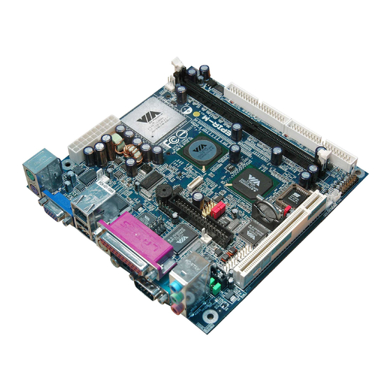
Specifications TV-Out • VIA VT1622/M (Macrovision) TV-Out Controller • Supports 640 x 480, 800 x 600, and 1024 x 768 NTSC/PAL TV Onboard I/O Connectors • Two 1394 connectors for two 1394 ports • Front-panel audio connectors (Mic and Line Out) •... - Page 13 Top: Mouse Bottom: S-Video / Middle: Line-Out Bottom: USB ports Bottom: Keyboard Composite COM1 Bottom: Mic CRT (VGA) SPDIF_SEL F_Audio CD_IN COM2 1394_1 SYSFAN 1394_2 USB 3/4 ATXPWR LVDS CLEAR_CMOS FAN3 CPUFAN DIMM F_PANEL IDE2 IDE1 VIA EPIA-M Mini-ITX Mainboard...
-
Page 14: Connectors Guide
Specifications Connectors Guide Component Function Reference SYSFAN/CPUFAN/FAN3 Fan power connectors See p. 2-2 DIMM DIMM slot See p. 2-4 ATX Power Connector Connecting ATX power supply See p. 2-6 PS/2 Mouse Mouse connector See p. 2-7 PS/2 Keyboard Keyboard connector See p. -
Page 15: Installation
Hardware Setup Installation This chapter provides you with the information about hard- ware setup procedures. While installing, be careful in holding the components and follow the installation procedures. Some components can be damaged if installed incorrectly. If possible, use a grounded wrist strap before handling computer components. -
Page 16: Cpu
Chapter 2 The VIA EPIA-M Mini-ITX Mainboard includes an embedded VIA Eden Proc- essor or VIA C3™ E-Series Processor. The CPUFAN (CPU fan) and SYSFAN (system fan) run on +12V and maintain system cooling. When connecting the wire to the connectors, always be aware that the red wire is the Positive and should be connected to the +12V. -
Page 17: The Via Eden Processor
Hardware Setup The VIA Eden Processor Providing ultra-low power consumption and advanced thermal dissipation properties, the VIA Eden Processor features a fanless design. The VIA Eden Processor requires only a heatsink, as shown below. CPU Heatsink Overclocking This motherboard is not designed to support overclocking. -
Page 18: Memory Installation
Chapter 2 Memory Installation The VIA EPIA-M Mini-ITX Mainboard provides one 184-pin DIMM slot for DDR266 SDRAM memory modules. DIMM DDR SDRAM Module Installation Procedures 1.) Push the white retaining latches at either end of the DIMM slot outwards. 2.) Align the DDR SDRAM module with the corresponding notches on the DIMM slot. -
Page 19: Available Ddr Sdram Configurations
Hardware Setup Available DDR SDRAM Configurations Refer to the table below for available DDR SDRAM configurations on the mainboard. Socket Memory Module Total Memory DIMM 64MB, 128MB, 64MB~1GB 256MB, 512MB, 1GB Maximum System Memory Supported... -
Page 20: Power Supply
Chapter 2 Power Supply The VIA EPIA-M Mini-ITX Mainboard requires an ATX power supply to be connected. Before inserting the power supply connector, always make sure that all components are installed correctly to ensure that no damage will be caused. -
Page 21: Back Panel
Hardware Setup Back Panel The back panel of the VIA EPIA-M Mini-ITX Mainboard contains the following connectors: LPT Connector RJ-45 Port PS/2 Mouse Line In Line Out Mic In COM Port PS/2 Keyboard S-Video Port RCA Video CRT Connector USB Ports... -
Page 22: Usb Port Connectors
Chapter 2 USB Port Connectors The mainboard provides 2 USB 2.0/1.1 ports (plus 1 pin-headers for up to 2 additional USB 2.0 connections). USB-compatible devices can be plugged directly into these ports. Pin Definition 5 6 7 8 SIGNAL DESCRIPTION -Data 0 Negative Data Channel 0 +Data 0... -
Page 23: Serial Port Connector: Com 1
Hardware Setup Serial Port Connectors: COM 1 The mainboard offers one 9-pin male Serial Port connector (COM 1) . You can attach a serial mouse or other serial devices directly to this port. Pin Definition 1 2 3 4 5 SIGNAL DESCRIPTION Data Carry Detect... -
Page 24: Connectors
Chapter 2 Connectors The VIA EPIA-M Mini-ITX Mainboard provides the following connectors: Hard Disk Connectors: IDE1 & IDE2 The mainboard has a 32-bit Enhanced PCI IDE and Ultra DMA 33/66/100/ 133 controller that provides PIO mode 0~4, Bus Master, and Ultra DMA 33/66/100/133 functions. -
Page 25: Case Connectors: F_Panel
Hardware Setup Case Connectors: F_PANEL The connector block F_PANEL allow you to connect to the Power Switch, Reset Switch, Power LED, HDD LED and SLED on the case. SIGNAL SIGNAL PW_LED+ HD_LED+ PW_LED+ HD_LED- PW_LED- PW_BN+ SPEAKER+ PW_BN- RST_SW+ RST_SW- SPEAKER- SLP_LED+ SLP_LED-... - Page 26 Chapter 2 Fast IrDA Infrared Module Connector: IR This connector allows you to connect an IrDA Infrared module. You must configure the setting through the BIOS setup to activate the IR function. Pin Definition SIGNAL IRRX 1 IRRX IRTX Consumer Infrared Module / PS2 Header: CIR / EXT_KBMS When the header is not in use, please short pin 3&5, pin 4&6, pin 7&9, and pin 8&10.
-
Page 27: Usb Pin-Header: Usb3/4
Hardware Setup USB pin-header: USB3/4 The mainboard provides 1 front USB pin-header connector, allowing up to 2 additional USB ports. Please plug the USB 2-port module onto this pin- header. USB 3/4 Pin Definition SIGNAL SIGNAL USB2- USB3- USB2+ USB3+ USB 3/4 Wake-On LAN Connector: WOL This connector allows you to connect a network card with the Wake-On LAN... -
Page 28: Firewire: Ieee1394
Chapter 2 FireWire: IEEE1394 FireWire is a serial I/O interface that provides you fast data transfer rates. There are 2 FireWire ports available. 1394_X Definition SIGNAL SIGNAL TPA0+ TPA0- TPB0+ TPB0- 1394_VDD 1394_VDD COM2: The Second Serial Port COM2 is a pin header for second serial port. Pin Definition SIGNAL DESCRIPTION... -
Page 29: Chassis Intrusion Connector: Ci
Hardware Setup Chassis Intrusion Connector: CI This connector is for a chassis designed with intrusion detection feature. It requires a chassis intrusion sensor or on a chassis. If any chassis component is moved, the sensor triggers and sends a high-level signal to this connector to record a chassis intrusion event. -
Page 30: Cd-In Connector: Cd_In
Chapter 2 CD-In Connector: CD_IN This connector is for the CD-ROM audio connector. CD_IN CD_GND CD_L CD_R C Connector: I This is for connecting a I C device. SIGNAL +3.3V +3.3V EL-ON SMBCK SMBDT 2-16... -
Page 31: Hardware Setup
Hardware Setup Front Audio Connector: F_Audio This connector allows you to connect audio jacks on front panel for convenient connection and control of audio devices. Note: 1. When the front audio board is not in use, use the mini jumper to connect pin 5&6 and pin 9&10 (default). -
Page 32: Jumpers
Chapter 2 Jumpers The mainboard provides jumpers for setting the mainboard’s functions. This section will explain how to change settings for your mainboard’s functions through the use of the jumpers. Clear CMOS Jumper: CLEAR_CMOS The onboard CMOS RAM stores system configuration data and has an onboard battery power supply. -
Page 33: Slots
Hardware Setup Slots PCI Slot The PCI slot allows you to insert PCI expansion card. When adding or re- moving expansion cards, make sure that you unplug the power supply first. Meanwhile, read the documentation for the expansion card to make any nec- essary hardware or software settings for the expansion card, such as jumpers, switches or BIOS configuration. -
Page 34: Bios Setup
BIOS Setup BIOS Setup This chapter gives you detailed explaination of BIOS setup functions. It consists of the following topics: Entering Setup Control Keys Getting Help The Main Menu Standard CMOS Features Advanced BIOS Features Advanced Chipset Features 3-11 Integrated Peripherals 3-13 Power Management Setup 3-17... -
Page 35: Entering Setup
Chapter 3 Entering Setup Power on the computer and press DEL straight away to enter the BIOS setup menu. If you missed the BIOS setup entry point, you may restart the system and try again. Control Keys < ↑ > Move to the previous item <... -
Page 36: Getting Help
BIOS Setup Getting Help After entering the BIOS setup menu, the Main Menu appears. Main Menu The main menu displays all BIOS setup categories. Use the control keys ( ) to select any item/sub-menu. Description of the selected/highlighted category is displayed at the bottom of the screen. -
Page 37: The Main Menu
Chapter 3 The Main Menu The Main Menu contains twelve setup functions and two exit choices. Use arrow keys to select the items and press <Enter> to accept or enter the sub- menu. Standard CMOS Features Use this menu to set basic system configurations. Advanced BIOS Features Use this menu to set the advanced features available on your system. - Page 38 BIOS Setup PC Health Status This menu shows the PC health status. Frequency/Voltage Control Use this menu to set the system frequency and voltage control. Load Fail-Safe Defaults Use this menu to load the BIOS default settings for minimal and stable system operations.
-
Page 39: Standard Cmos Features
Chapter 3 Standard CMOS Features Use the arrow keys to highlight the item and use the <PgUp> or <PgDn> keys to select the value you desire for each item. Date The date format is <Day><Month><Date><Year>. Day - day of the week, for example Friday. Read-only. Month - the month from Jan to Dec. - Page 40 BIOS Setup No Errors System does not halt for any error. All, But Keyboard System halts for all errors (except keyboard error). All, But Diskette System halts for all errors (except diskette error). All, But Disk/Key System halts for all errors (except disk/keyboard error) IDE Primary Master/Slave and Secondary Master/Slave Press <Enter>...
-
Page 41: Advanced Bios Features
Chapter 3 Advanced BIOS Features Virus Warning Set the Virus Warning feature for IDE Hard Disk boot sector protection. If the function is enabled, any attempt to write data into this area will cause a beep and a warning message will be displayed. Settings: Disabled and Enabled. CPU L2 Cache ECC Checking Set the ECC (Error-Correcting Code) feature for Level 2 cache. - Page 42 BIOS Setup SCSI The system will boot from SCSI. CD-ROM The system will boot from CD-ROM. HDD-1 The system will boot from second HDD. HDD-2 The system will boot from third HDD. HDD-3 The system will boot from fourth HDD. ZIP100 The system will boot from ATAPI ZIP drive.
-
Page 43: Security Option
Chapter 3 Typematic Delay (Msec) When Typematic Rate Setting is enabled. This item allows you to select the delay between when the key was first pressed and when the acceleration begins. Settings: 250, 500, 750 and 1000. Security Option Specifies the type of BIOS password protection that is implemented. Settings are described below: Option Description... -
Page 44: Advanced Chipset Features
BIOS Setup Advanced Chipset Features The Advanced Chipset Features menu is used for optimizing the chipset functions. Note: Change these settings only if you are familiar with the chipset. AGP Aperture Size This setting controls how much memory space can be allocated to AGP for display purposes. - Page 45 Chapter 3 If Disabled, CPU must wait after each write cycle until PCI bus signals that it is ready to receive more data. Settings: Enabled and Disabled. Select Display Device Set the device you want to use for displaying. Settings: CRT and TV. TV Type Set the TV type you would like to use.
-
Page 46: Integrated Peripherals
BIOS Setup Integrated Peripherals Onboard IDE Channel 1/2 The integrated peripheral controller contains an IDE interface with sup- port for two IDE channels. Choose Enabled to activate each channel separately. Settings: Disabled, Enabled. IDE Prefetch Mode This allows your hard disk controller to use the fast block mode to trans- fer data to and from the hard disk drive. - Page 47 AC97 Audio Auto allows the mainboard to detect whether an audio device is used. If the device is detected, the onboard VIA AC’97 (Audio Codec’97) con- troller will be enabled; if not, it is disabled. Disable the controller if you want to use other controller cards to connect an audio device. Set- ting options: Auto and Disabled.
-
Page 48: Onboard Fdc Controller
BIOS Setup SuperIO Device Press <Enter> to enter the sub-menu and the following screen appears: Onboard FDC Controller Enable the onboard floppy controller. Select “Enabled” when you have installed a floppy disk drive. Settings: Enabled and Disabled. Onboard Serial Port 1/2 Set the base I/O port address and IRQ for the onboard serial port A/serial port B. - Page 49 Chapter 3 SPP : Standard Parallel Port EPP : Enhanced Parallel Port ECP : Extended Capability Port ECP + EPP: Extended Capability Port + Enhanced Parallel Port EPP Mode Select Select the Enhance Parallel Port mode. Settings: EPP1.9 and EPP1.7. ECP Mode Use DMA ECP utilises a DMA channel.
-
Page 50: Power Management Setup
BIOS Setup Power Management Setup The Power Management Setup menu configures the system to most effec- tively save energy while operating in a manner consistent with your own style of computer use. ACPI Function Activate the ACPI (Advanced Configuration and Power Management Interface) Function. - Page 51 Chapter 3 Power Management Timer Set the idle time before system enters power saving mode. ACPI OS such as Windows XP will override this option. Settings: Disable and 1/ 2/4/6/8/10/20/30/40 min and 1 hr. Video Off Option Select whether or not to turn off the screen when system enters power saving mode, ACPI OS such as Windows XP will override this option.
-
Page 52: Peripheral Activities
BIOS Setup Peripheral Activities Press <Enter> to enter the sub-menu and the following screen appears: VGA Event Decide whether or not the power management unit should monitor VGA activities. Settings: Off and ON. LPT & COM Event Decide whether or not the power management unit should monitor parallel port (LPT) and serial port (COM) activities. - Page 53 Chapter 3 PS2KB Wakeup from suspend Select which “Hot-Key” is used to wake-up the system from power saving mode. Settings: Disabled, Ctrl+F1, Ctrl+F2, Ctrl+F3, Ctrl+F4, Ctrl+F5, Ctrl+F6, Ctrl+F7, Ctrl+F8, Ctrl+F9, Ctrl+F10, Ctrl+F11, Ctrl+F12, Power, Wake and Any Key. USB Resume Decide whether or not the USB devices can wake the system from suspend state.
- Page 54 BIOS Setup IRQs Activities Press <Enter> to enter the sub-menu and the following screen appears: Primary INTR Selecting ON will cause the system to wake up from power saving modes if activity is detected from any enabled IRQ channels. Settings: OFF and IRQ3~IRQ15 Enables or disables the monitoring of the specified IRQ line.
-
Page 55: Pnp/Pci Configurations
Chapter 3 PNP/PCI Configurations This section describes the BIOS configuration of the PCI bus system. This section covers some very technical items and it is strongly recommended that only experienced users should make any changes to the default settings. PNP OS Installed When set to Yes, BIOS will only initialize the PnP cards used for booting (VGA, IDE, SCSI). - Page 56 BIOS Setup IRQ Resources The items are adjustable only when Resources Controlled By is set to Manual. Press <Enter> and you will enter the sub-menu of the items. IRQ Resources list IRQ 3/4/5/7/9/10/11/12/14/15 for users to set each IRQ a type depending on the type of device using the IRQ.
-
Page 57: Pc Health Status
Chapter 3 PC Health Status This section shows the status of your CPU, fan, warning for overall system status. Current CPU Temp, CPU Fan Speed, System Fan Speed, +12V, +5V, +3.3V, CPU Vcore. These items display the current status of all of the monitored hardware devices/components such as CPU voltages, temperatures and all fans’... -
Page 58: Dram Timing
BIOS Setup Frequency/Voltage Control DRAM Clock The chipset supports synchronous and asynchronous mode between host clock and DRAM clock frequency. Settings: By SPD, 100MHz and 133MHz. DRAM Timing This setting determines whether DRAM timing is configured by reading the contents of the SPD (Serial Presence Detect) EPROM on the DRAM module. Selecting Yes makes SDRAM Cycle Length and Bank Interleave automatically determined by BIOS according to the configurations on the SPD. -
Page 59: Dram Burst Len
Chapter 3 Active to Precharge (Tras) Set the time from active back to precharge state. Settings: 5T and 6T. Active to CMD (Trcd) Set the time from active state to command state. Settings: 2T and 3T. DRAM Command Rate This setting controls the DRAM command rate. Selecting 1T allows DRAM signal controller to run at 1T (T=clock cycles) rate. -
Page 60: Load Fail-Safe Defaults
BIOS Setup Load Fail-Safe Defaults This option on the main menu allows users to restore all the BIOS settings to the default Fail Safe values. These values are set by the mainboard manufac- turer to provide the most stable system. When you select Load-Fail Safe Defaults, a message as below appears: Pressing ‘Y’... -
Page 61: Load Optimized Defaults
Chapter 3 Load Optimized Defaults This option on the main menu allows users to restore all the BIOS settings to the default Optimized values. The Optimized Defaults are the default values also set by the mainboard manufacturer for both optimized and stable perform- ance of the mainboard. -
Page 62: Set Supervisor/User Password
BIOS Setup Set Supervisor/User Password When you select this function, a message as below will appear on the screen: Type the password, up to eight characters in length, and press <Enter>. The password typed now will clear any previously set password from CMOS memory. - Page 63 Chapter 3 About Supervisor Password & User Password: Supervisor password : Can enter and change the settings of the setup menus. User password: Can only enter but do not have the right to change the settings of the setup menus. 3-30...
-
Page 64: Save & Exit Setup
BIOS Setup Save & Exit Setup When you want to quit the Setup menu, you can select this option to save the changes and quit. A message as below will appear on the screen: Typing “Y” will allow you to quit the Setup Utility and save the user setup changes to RTC CMOS. -
Page 65: Exit Without Saving
Chapter 3 Exit Without Saving When you want to quit the Setup menu, you can select this option to abandon the changes. A message as below will appear on the screen: Typing “Y” will allow you to quit the Setup Utility without saving any changes to RTC CMOS. -
Page 66: Software Setup
It consists of the following topic: Driver Utilities CD Content Note: You must install VIA chipset drivers first before installing other drivers such as audio or VGA drivers. The applications will only function correctly if the nec-... -
Page 67: Driver Utilities Cd Content
Driver Utilities CD Content Getting Started The VIA EPIA-M mainboard includes a Driver Utilities CD which contains driver utilities and software to enhance the performance of the mainboard. Please check that you have this CD in your gift box. If the CD is missing in your gift box, please contact your local dealer for the CD. - Page 68 Driver Setup The driver utilities and software in this CD are: - VIA 4in1 Drivers: Contains VIA ATAPI Vendor Support Driver (enables the performance enhancing bus mastering functions on ATA-capable Hard Disk Drives and ensures IDE device compatibility), AGP VxD Driver (provides...
-
Page 69: Appendix
Appendix 5 5 5 5 5 Appendix This chapter gives you brief descriptions of how Smart 5.1 is enabled. It consists of the following topics: Smart 5.1 - Intelligent 6 Channel Audio... -
Page 70: Smart 5.1 - Intelligent 6 Channel Audio
Chapter 5 Smart 5.1 - Intelligent 6 Channel Audio Enabling Smart 5.1 Intelligent 6 Channel Audio Smart5.1 allows the user to output 6 channel audio directly from the audio jacks on the mainboard, using the traditional line-in and microphone jacks as output jacks. - Page 71 Appendix 3. Choose [5.1 surround sound speakers] to support the 6 channel function.
- Page 72 Chapter 5 Example B 1. Double click [Sounds and Audio Devices] icon in Control Panel and then select [Audio] tab on the panel as shown below. Press [Volume] button in the [Sound playback] column. 2. [Front Speaker] panel appears and then select [Options] menu to check the item [Advanced Controls].
- Page 73 Appendix 3. Then [Front Speaker] panel displays [Advanced] button and press it. 4. Check the item [Smart5.1 Enable] in the panel below.
- Page 74 Chapter 5 After completing the previous settings, you just have to connect your speak- ers to the 3 Jack Connector like shown below. Now your Smart 5.1 capabili- ties are enabled. Rear Front Center Following the system setup, users need to install software for playing DVD. Currently the two main DVD-playing applications are WIN-DVD v4.0 and Power DVD XP v4.0.
- Page 75 Appendix 2. The panel of Audio Effect appears and click on the lower right corner button as shown in the picture below. 3. The [Setup] panel appears and select [Audio] tab. Then choose the item [6 Channel (5.1 Home Theater)] in the column of [Audio Speaker Configuration] .
- Page 76 Chapter 5 Power-DVD XP v4.0 1. Open the application and click on the [Configuration] icon shown as the picture below. 2. The panel of Configuration appears and select [Audio] tab. Then choose [6 Speaker] in the column of [Audio Output] and click [Ok]. Through the system operation and software settings, users can take advan- tage of Smart 5.1 6-channel output with ease!
Need help?
Do you have a question about the EPIA-M Mini-ITX and is the answer not in the manual?
Questions and answers