Hughes HX200 Installation Manual
Hx system satellite router
Hide thumbs
Also See for HX200:
- User manual (20 pages) ,
- Installation manual (140 pages) ,
- Installation procedure (18 pages)

Related Manuals for Hughes HX200


Summary of Contents for Hughes HX200
- Page 1 HX System HX200 Satellite Router Installation Guide 1038054-0001 Revision B July 7, 2011...
- Page 2 Hughes Network Systems, LLC has made every effort to ensure the correctness and completeness of the material in this document. Hughes Network Systems, LLC shall not be liable for errors contained herein. The information in this document is subject to change without notice. Hughes Network Systems, LLC makes no warranty of any kind with regard to this material, including, but not limited to, the implied warranties of merchantability and fitness for a particular purpose.
-
Page 3: Understanding Safety Alert Messages
Understanding safety alert messages Safety alert messages call attention to potential safety hazards and tell you how to avoid them. These messages are identified by the signal words DANGER, WARNING, CAUTION, or NOTICE, as illustrated below. To avoid possible property damage, personal injury, or in some cases possible death, read and comply with all safety alert messages. -
Page 4: Safety Symbols
Safety symbols The generic safety alert symbol calls attention to a potential personal injury hazard. It appears next to the DANGER, WARNING, and CAUTION signal words as part of the signal word label. Other symbols may appear next to DANGER, WARNING, or CAUTION to indicate a specific type of hazard (for example, fire or electric shock). -
Page 5: Table Of Contents
HX200 features........2... - Page 6 Uploading the SBC configuration file to the HX200 ..39 Commissioning the HX200 ......41 Chapter 4 Completing the installation .
- Page 7 HX200 LEDs ........91...
- Page 8 Appendix A Configuring a Windows computer to support DHCP ........105 Windows XP.
- Page 9 Material compliance ....... . .142 RoHS compliance....... . .142 RoHs compliance with exemptions .
- Page 10 • Contents 1038054-0001 Revision B...
-
Page 11: Introduction
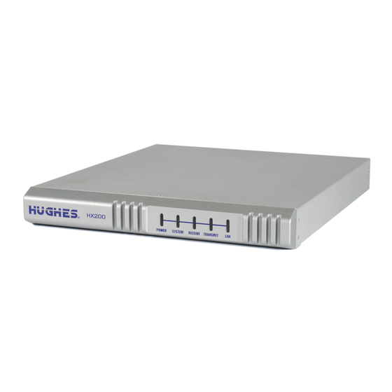
• Call center operators, who respond to customers’ calls • Call center trainers, who train call center operators HX200 satellite router The HX200, as shown in Figure 1 on page 2, is a high-performance satellite router designed to support provide overview carrier-grade IP services using dynamically assigned high-bandwidth satellite IP connectivity. -
Page 12: Hx200 For Stabilized Platforms
Figure 1: HX200 satellite router (front and back) An optional rack mount kit is available for the HX200, which allows the HX200 to be installed in an industry standard 19” (0.45 m) rack. HX200 for stabilized An enhancement to the HX200 supports stabilized platforms for the Coastal Maritime Service. -
Page 13: Transmission Types
– Saturated Ku-band – Saturated C-band • DVB-S and DVB-S2 compliant outroutes • Mobility The HX200 satellite router provides support for the following capabilities: • L-band transmitter • Serial NMEA interface to global positioning system (GPS) • Inroute spreading – 256 Ksps X 2 –... -
Page 14: Dvb-S2 Compliant Outroute
C-Band External Reference PLL LNBs C Band PLL LNB Norsat / 3020XF 1502443-0001 DVB-S2 compliant outroute The HX200 receives a single Digital Video Broadcast - second generation (DVB-S2) compliant outroute. Mobility The HX200 provides doppler compensation for radial speeds up to 150 mph. -
Page 15: Hx200 Specifications
HX200 specifications Physical, satellite, and Table 2 lists the physical, satellite, and mechanical specifications for the HX200 satellite router. mechanical specifications Table 2: HX200 satellite router specifications Product element Specification Physical Interfaces Two 10/100 BaseT Ethernet LAN RJ45 ports (independent subnets) -
Page 16: Transmitter And Receiver Specifications
Transmitter and receiver Tables 3 and 4 list the HX200 transmitter specifications and receiver specifications, respectively. specifications Table 3: HX200 Transmitter Specifications Property Value Linear transmit radio L-band output frequency range 950 — 1700 MHz L-band output with OQPSK modulation... -
Page 17: Dvb-S2 Compliant Outroute Rates And Ratios
DVB-S2 compliant outroute The HX200 receives a single Digital Video Broadcast - second generation (DVB-S2) compliant outroute as defined in Table 5. rates and ratios Table 5: Outroute rates and ratios Acquisi- Encap- Signaling Modulation FEC Mode Rate BER/PER tion... -
Page 18: Contact Information
Commissioning is the process of registering an HX200 satellite router for service. During the commissioning process you may use auto selection or manual entry of parameters. • Auto Selection - Allows you to choose the Network Access Provider (NAP) from a predetermined list of providers. Many of the commissioning parameters are automatically configured for the provider chosen. - Page 19 Table 6: Radios and LNBs Hughes product Description Vendor number 10W Linear BUC NJRC/ NJT5762N 9506222-0001 Ku-Band Low Stability LNBs Dom/Intl LNB 1500320-0006 Intelsat 1500287-0001 AsiaSat/Eutelsat 1500287-0003 Universal Ku-Band LNB Invacom 1501882-0002 C-Band Low Stability LNBs Extd C-Band LNB 1024573-0001...
- Page 20 Chapter 1 • Introduction 1038054-0001 Revision B...
-
Page 21: Assembling And Connecting Hx200 Hardware
This chapter explains how to assemble and make the connections to the HX200 satellite router. Preparing for the installation Items required for To install an HX200 satellite router, first ensure that you have the following items listed below: installation • HX200 satellite router • Power cord •... -
Page 22: Confirming Installer Laptop And Site Requirements
(if instructed to install sbc.cfg it). Remote site requirements IP devices connected to an HX200 satellite router must implement the standard TCP/IP stack and provide an Ethernet interface; otherwise there is no constraint to the platforms and operating systems of devices attached to the satellite routers. -
Page 23: Conducting The Site Survey
Connecting the receive Connect the receive cable to the Satellite In connector on the HX200 satellite router as shown in Figure 2. and transmit cables Figure 2: Connecting the receive and transmit cables to the satellite router The HX200 offers three radio transmit options: Ku-band, saturated, or linear. -
Page 24: Connecting The Ethernet And Power Cables
Use either the Manual Commissioning screen or one of the Satellite Based Commissioning screens to select the radio type as described in Chapter 3 – Commissioning the HX200 satellite router on page 21. You may select only one radio transmit option at any time. Connecting the Ethernet Select a location for the satellite router that accommodates all required cable connections, including the power source. -
Page 25: Serial Port Interface Connections
Note: Do not connect any devices to the HX200 at this time. Connect serial and Ethernet devices to the device only after it is fully installed and commissioned. CAUTION Do not connect or disconnect the Tx or Rx IFL cable while the IDU is powered on;... -
Page 26: Connecting The Hardware For Stabilized Platforms
• HX200 demodulator lock indicator – Output from the HX200 on serial port pin 15 – This HX200 output signal is used to indicate to the antenna system the current status of the HX-200 demodulator – Signal reaction time to demodulator lock state change - nominally 20 milliseconds –... - Page 27 Axis Stabilizer Installation and Operations Manual (Version 2.0). Figure 4: Connecting the hardware components - Seatel DAC 2200 configuration Chapter 2 • Assembling and connecting HX200 hardware 1038054-0001 Revision B...
-
Page 28: Powering Up And Observing The Leds
Powering up and Turn the AC power switch located on the satellite router to ON. observing the LEDs When power is applied to the HX200, or after it resets, the satellite router light-emitting diodes (LEDs) will light in the following sequence. -
Page 29: Stabilized Platforms
4. The Power LED blinks, indicating that the unit is not commissioned and therefore is running fallback.bin rather than main.bin. Note: In countries outside North America, the HX200 may be plugged directly into a 240V outlet with a replacement power cord. Different countries may have different standards and requirements. CAUTION •... - Page 30 Chapter 2 • Assembling and connecting HX200 hardware 1038054-0001 Revision B...
-
Page 31: Commissioning The Hx200 Satellite Router
The most common method of commissioning the satellite router is manual commissioning. Manual commissioning assumes the HX200 satellite router has already been pre-configured at the NOC, the outdoor unit (ODU) and indoor unit (IDU) have been successfully installed, and the dish is pointed correctly. If all the above conditions are met, you can manually commission the router. -
Page 32: Accessing The Manual Commissioning Interface
Follow these steps to access the manual commissioning interface: commissioning interface The Manual Commissioning interface can be accessed from any browser as follows: 1. Type the following URL to navigate to the Advance page: http://192.168.0.1/fs/advanced/advanced.html Chapter 3 • Commissioning the HX200 satellite router 1038054-0001 Revision B... - Page 33 2. Click the Setup link (Figure 6) to display the Setup page shown in Figure 7. Figure 6: Advance page Chapter 3 • Commissioning the HX200 satellite router 1038054-0001 Revision B...
- Page 34 3. Click the VSAT Manual Commissioning link on the Setup page (Figure 7) to display the HX200 Manual Commissioning Page as shown in Figure 8. Figure 7: Commissioning Setup page Alternately, you can navigate to the Terminal Manual Commissioning Page from the System Control Center as follows: a.
- Page 35 Figure 8: Satellite Parameters VSAT parameters LAN Parameters Management Parameters Receive Radio Parameters Transmit Radio Parameters Figure 8: Broadband Satellite HX200 Manual Commissioning screen Chapter 3 • Commissioning the HX200 satellite router 1038054-0001 Revision B...
- Page 36 Note: If an incorrect value is entered for any field on the Manual Commissioning page, an error message displays and the form cannot be submitted until the error is corrected. Chapter 3 • Commissioning the HX200 satellite router 1038054-0001 Revision B...
-
Page 37: Entering Satellite Parameters
• West • Frequency (x 100Khz) - Required • Symbol Rate (Sps) - Required • LNB 22KHz Switch (drop-down) • Receive Polarization - Required – Vertical – Horizontal – Left Chapter 3 • Commissioning the HX200 satellite router 1038054-0001 Revision B... -
Page 38: Entering Vsat Parameters
The following parameters must be entered (Figure 11): Figure 11: VSAT Parameters section • Longitude – Degrees – Minutes – Hemisphere (drop-down) • East • West • Latitude – Degrees Chapter 3 • Commissioning the HX200 satellite router 1038054-0001 Revision B... -
Page 39: Entering Lan Parameters
• LAN 1 IP Address - A typical installation uses the IP address of 192.168.0.1. • LAN 1 Subnet Mask • LAN 2 IP Address • LAN 2 Subnet Mask Chapter 3 • Commissioning the HX200 satellite router 1038054-0001 Revision B... -
Page 40: Entering Management Parameters
– Receive Only - Use where not return path is used. – Inroute - Typical installations use the inroute default. – LAN 1 – LAN 2 • Dynamic Routing Enabled (drop-down) Chapter 3 • Commissioning the HX200 satellite router 1038054-0001 Revision B... -
Page 41: Entering Receive Radio Parameters
• LNB 10 Mhz On (check-box) - Check the box for LNBs that require external 10 MHz reference. • LO Freq (MHz) • Band Lower Edge (MHz) • Band Upper Edge (MHz) Chapter 3 • Commissioning the HX200 satellite router 1038054-0001 Revision B... -
Page 42: Entering Transmit Radio Parameters
– LO Frequency (MHz) – Band Lower Edge (MHz) – Band Upper Edge (MHz) – Radio Wattage (W) – Total Gain (dB) – 1 db G.C.P(dB) Chapter 3 • Commissioning the HX200 satellite router 1038054-0001 Revision B... -
Page 43: Set Maximum Tx Power/Minimum Attenuation
(i.e. the output from the modem) is -12 dB. Given the modem output power with no attenuation is 0 dB, the Minimum Attenuation value should be set at 12 dB. Chapter 3 • Commissioning the HX200 satellite router 1038054-0001 Revision B... -
Page 44: Noc Override
Follow these steps to use the Antenna Pointing feature on the HX200 web-based interface to peak the receive and transmit signals: 1. Turn off the HX200 using the power switch on the rear panel. 2. Connect the receive and transmit coaxial cables to the HX200. - Page 45 Enable OPI Figure 16: Antenna pointing screen 7. Click Next. The Receive Antenna Pointing screen appears as shown in Figure 17. Chapter 3 • Commissioning the HX200 satellite router 1038054-0001 Revision B...
- Page 46 11. If required, the satellite router may need to run automatic cross-polarization (ACP) if it is present. If ACP is present, the timing units tells the satellite router it is present, and this Chapter 3 • Commissioning the HX200 satellite router 1038054-0001 Revision B...
-
Page 47: Satellite-Based Commissioning
Refer to Appendix A for instructions on how to configure a Windows computer to use DHCP. 2. Verify that the installer laptop is connected to the HX200 by an Ethernet cable. 3. Open a command window on the installer laptop and obtain an IP address from a DHCP server. - Page 48 If the NIC is installed properly and the installer laptop is configured properly, make sure all cable connections are secure. (See the Caution statement that follows Figure 2 on page 13). Chapter 3 • Commissioning the HX200 satellite router 1038054-0001 Revision B...
-
Page 49: Uploading The Sbc Configuration File To The Hx200
1. Open a browser on the installer laptop. 2. Type http://192.168.0.1/fs/registration/ in the address bar and press E . If an setup.html NTER alternate IP address was assigned to the satellite router at the Chapter 3 • Commissioning the HX200 satellite router 1038054-0001 Revision B... - Page 50 PC where the file is saved. sbc.cfg 5. Select the file and click Open. 6. Click Upload. 7. Click Close to return to the Setup screen. Chapter 3 • Commissioning the HX200 satellite router 1038054-0001 Revision B...
-
Page 51: Commissioning The Hx200
2. Enter the ZIP code of the location in which you are installing the satellite router and click Next. If installing the HX200 outside the United States, you can enter the location manually by completing steps a and b below. - Page 52 Enter the correct latitude and longitude for the location and click Next. Figure 22: Entering location manually Chapter 3 • Commissioning the HX200 satellite router 1038054-0001 Revision B...
- Page 53 Select the check box Enter satellite parameters manually on the Satellite Parameters screen. Chapter 3 • Commissioning the HX200 satellite router 1038054-0001 Revision B...
- Page 54 • Receive polarization • Transmit polarization • 22KHz tone • Frequency Band/Modulation • Digital video broadcast (DVB) Mode • DVB Program Number (User Data) • DVB Program Number (DNCC Data) Chapter 3 • Commissioning the HX200 satellite router 1038054-0001 Revision B...
- Page 55 Note: You are only required to verify satellite parameters if you selected the satellite and transponder as shown in Figure 24. If you entered the satellite parameters manually, the Verification of Satellite Parameters screen does not appear. Chapter 3 • Commissioning the HX200 satellite router 1038054-0001 Revision B...
- Page 56 8. Select the LNB in use from the drop-down list. Click Next. 9. Verify your information is correct on the Verification of Receive LNB Parameters screen as shown in Figure 28 on page 47. Click Next. Chapter 3 • Commissioning the HX200 satellite router 1038054-0001 Revision B...
- Page 57 Click Next. Figure 29: Transmit Radio Parameters screen 11. Verify your information is correct on the Verification of Transmit Radio Parameters screen as shown in Figure 30. Click Next. Chapter 3 • Commissioning the HX200 satellite router 1038054-0001 Revision B...
- Page 58 12. The Receive Antenna Pointing screen appears as shown in Figure 31. Figure 31: Receive Antenna Pointing 13. To view a graphic representation of the current signal quality (Figure 32), click Display Signal Strength. Click Close. Chapter 3 • Commissioning the HX200 satellite router 1038054-0001 Revision B...
- Page 59 ACP. The satellite router automatically inquires for validation when the timing unit indicates ACP is present. Based on the ACP configuration, the satellite router may occasionally Chapter 3 • Commissioning the HX200 satellite router 1038054-0001 Revision B...
- Page 60 Figure 33: Auto Cross Pol screen 18. During this process a series of messages appear as testing progresses as shown in the screens that follow. 19. Click Continue. 20. Click Close. Chapter 3 • Commissioning the HX200 satellite router 1038054-0001 Revision B...
- Page 61 24. Click Next when prompted to do so. 25. Click OK on the pop-up dialog shown in Figure 35 to access the registration server. Figure 35: Accessing the registration server Chapter 3 • Commissioning the HX200 satellite router 1038054-0001 Revision B...
- Page 62 Figure 36, click Yes to accept the security certificate. Figure 36: Accepting the security certificate 27. Enter the site ID on the enterprise Registration screen shown in Figure 37 and click Continue. Chapter 3 • Commissioning the HX200 satellite router 1038054-0001 Revision B...
- Page 63 31. To complete the commissioning process, close the Terminal Reset screen. The satellite router resets and is now commissioned. Continue with Chapter 4 – Completing the installation, on page 55. Chapter 3 • Commissioning the HX200 satellite router 1038054-0001 Revision B...
- Page 64 Chapter 3 • Commissioning the HX200 satellite router 1038054-0001 Revision B...
-
Page 65: Completing The Installation
This chapter discusses tasks that must be completed after the HX200 satellite router has been installed and commissioned. Confirming that all files Follow these steps to confirm that the HX200 satellite router is operating with the most current software version: are current 1. -
Page 66: Connecting The Hx200 Satellite Router To A Computer
Connecting the HX200 Using an Ethernet cable, connect the HX200 satellite router to the remote user’s computer as shown in Figure 38. You can also satellite router to a connect an Ethernet hub, router, or switch to the HX200 to... -
Page 67: Printing The System Information Page
4. Assuming that Internet connectivity is provided through the system gateway, type the URL of a known Website such as ; otherwise, attempt to use an enterprise www.HUGHES.com network resource. 5. Instruct the user that for routine technical support, access and refer to the contact information on the System Control Center Help page. -
Page 68: Creating A Shortcut To The System Control Center
Creating a shortcut to Follow these steps to create a shortcut to the HX200 System Control Center on the user’s computer desktop: the System Control Center 1. Right-click anywhere on the computer desktop and select from the popup menu as shown in Figure 39. - Page 69 4. Type in the field on the Select a System Control Center Title for the Program dialog as shown in Figure 41. Figure 41: Entering the name of the shortcut 5. Click Finish to save the shortcut to the user’s desktop. Note: It may be useful to add the System Control Center to your browser’s Favorites or Bookmark list.
- Page 70 Chapter 4 • Completing the installation 1038054-0001 Revision B...
-
Page 71: The System Control Center
Chapter 5 The System Control Center This chapter describes the HX200 System Control Center, which provides system status, configuration information, and online documentation. The HX200 internal software is updated periodically over the satellite link to the HX system gateway. Refer to System Control Center Help page on page 88 for current information about the System Control Center and satellite router software. -
Page 72: System Control Center Home Page
Figure 42: System Control Center home page System Control Center The System Control Center Home page contains system indicators and links to HX200 features and important information Home page regarding the operation of the HX200 satellite router. System indicators At the top of the Home page, you will see four system indicators which provide access to the four main System Control Center pages. -
Page 73: Links
If the System Status indicator is green and OK appears below it as shown in Figure 43, the satellite connection is operating properly. Figure 43: System indicators If the indicator is red and Problem appears below it as shown in Figure 44, there is a problem with satellite connectivity. Click on the indicator to access the System Status page to view problem details. -
Page 74: System Status
Help The links in the Help group provide access to various Help topics. • Getting Started provides an overview of satellite router operation as well as access to HX200 operating instructions and recommended settings. • View Help Topics provides access to the Help page, which... -
Page 75: System Status Page
System Status page The System Status page shown in Figure 45 displays general status information such as signal strength, receive status, transmit status, commissioning status, transmission control protocol (TCP) acceleration status, and Web acceleration status. Each of these categories is explained below. To access the System Status page, click on the System Status indicator on the Home page. -
Page 76: Reception Information Page
• Indicates whether the satellite router Commission Status – has been commissioned. • Indicates whether TCP TCP Acceleration Status – Acceleration is operational. TCP Acceleration provides the expected performance on a satellite router. Reception Information The Reception Information page shown in Figure 46 provides satellite router receive data such as receive status, number of page frames received, frames that contain errors, and bad key frames. -
Page 77: Receive Status Messages
• Indicates the current modulation and Current Modcod – coding scheme used on the HX200 DVB-S2 outroute. Receive status messages Table 7 lists the messages that may appear in the Receive Status field. The Corrective Actions column provides detailed information about each code and describes any possible corrective measures. - Page 78 Table 7: Receive code (RxCode) messages and corrective actions Code Message Corrective actions The receiver is in pointing mode Indicates that the installer is performing antenna pointing. In this mode, the transmitter is disabled because the installer is working near the antenna. If this occurs during normal operation, power-cycle the satellite router by turning the unit off, waiting 15 seconds, and turning it back on.
- Page 79 Table 7: Receive code (RxCode) messages and corrective actions (Continued) Code Message Corrective actions The receiver is operational Normal operating state for the receiver. Indicates that data is being received from the system gateway. The transmitter will only operate correctly when the receiver is in this state.
-
Page 80: Transmission Information Page
Transmission The Transmission Information page shown in Figure 47 displays satellite router transmit data such as transmit status, the number Information page of packets submitted for transmission, the number of successful transmissions, and the number of failed transmissions. Each of these fields is described below. - Page 81 If a problem cannot be resolved by following the corrective measures, contact Technical Support. TxCode 8 indicates that the transmitter is working properly. This code should appear most often. Note: The messages and associated corrective actions listed in Table 8 are current only as of this document’s release. To ensure that you have the most recent information regarding these messages, click on the blue Transmission Info indicator at the top of the screen and select the Transmit...
- Page 82 Table 8: Transmit code (TxCode) messages and corrective actions (Continued) Code Message Corrective actions The transmitter is not available because the Occurs when the transmitter is disabled for safety satellite receiver is not tuned for normal reasons. If this condition occurs during installation or operation commissioning, close the Antenna Pointing program and resolve the problem.
- Page 83 Table 8: Transmit code (TxCode) messages and corrective actions (Continued) Code Message Corrective actions The transmitter is unable to range because it Ranging is the automated process of adjusting cannot communicate with the gateway satellite transmitter timing and power. The satellite transmitter performs ranging as necessary to ensure that it can communicate successfully with the HX system gateway.
- Page 84 Table 8: Transmit code (TxCode) messages and corrective actions (Continued) Code Message Corrective actions The satellite transmitter is unable to obtain an Occurs if the transmitter is unable to range available transmission rate successfully. Ranging is the automated process of adjusting the satellite transmitter timing and power.
- Page 85 Table 8: Transmit code (TxCode) messages and corrective actions (Continued) Code Message Corrective actions The transmitter is disabled because a transmit Occurs when the transmitter fails a transmit pointing pointing test failed test, thereby indicating that the transmitter did not meet the minimum specifications required.
-
Page 86: System Information Page
System Information The System Information page shown in Figure 48 displays system information such as satellite router IP address, and site ID. page While all the information displayed on the System Information page may be useful, this section describes only the most important items. - Page 87 – Polarization orientation; either Receive Polarization – horizontal or vertical. – IP address of the primary system Router Address – gateway router used to route data sent by the satellite router. • Software Configuration section Network address – translation (NAT), DHCP, and firewall features are enabled or disabled at the system gateway per site requirements and cannot be changed by remote users.
-
Page 88: Connectivity Test Page
A screen for viewing firewall statistics is also available when the firewall option is enabled. Note that the port forwarding option can only be configured when network address port translation (NAPT) has been enabled for the HX200 at the HX system gateway. Firewall Configuration page... - Page 89 navigation area of the four main System Control Center pages. Firewall Configuration link opens the Firewall Configuration page shown in Figure 50. Figure 50: Firewall configuration page Chapter 5 • The System Control Center 1038054-0001 Revision B...
-
Page 90: Understanding How The Firewall Works
The firewall feature provides firewall protection for the computers connected to the HX200. The firewall rules that you create apply only to inbound traffic; that is, network traffic sent from the HX system gateway to the satellite router. - Page 91 The Firewall Rule Configuration page shown in Figure 51 appears. Note Figure 51 shows the page with the Protocol pull-down menu displayed. Type 3. Enter values in the Firewall Rule Configuration page as indicated in the field definitions in Table 9. Note: To clear the fields in the rule configuration page and start over, click Restore.
-
Page 92: Modifying And Deleting Firewall Rules
Table 9: Firewall rule configuration fields (Continued) Field name Value Description Protocol Type This is the Protocol that is encapsulated in the IP packet. A value of OTHER indicates the value in the If “Other”, specify Protocol ICMP Number field should be used. OTHER Source Port One or more... -
Page 93: Enabling And Disabling The Firewall
Enabling and disabling the Once firewall rules have been created, you can enable the firewall firewall. You can also disable the firewall at any time. • To enable the firewall, select the checkbox Enable Firewall located in the upper left corner of the firewall rule list, then click Submit. -
Page 94: Viewing Firewall Statistics
Viewing firewall statistics To view the Firewall Statistics page, click the Firewall Statistics link in the navigation area on the left-hand side of the System Control Center page. The Firewall Statistics page shown in Figure 53 appears. Figure 53: Firewall Statistics page Resetting firewall statistics To reset the firewall statistics counters to zero, click Clear counters... -
Page 95: Port Forwarding Configuration Page
Port Forwarding If an HX200 is connected to a system gateway that has NAPT enabled, and the satellite router is configured at the system Configuration page gateway to allow local port forwarding control, a Port Forwarding Configuration link will appear in the navigation area on the left side of the System Control Center page. -
Page 96: Port Forwarding Rule Restrictions
The port forwarding feature also translates the port number in received traffic before sending it to its destination by replacing the received destination port value with a different one. Port forwarding is configured using port forwarding rules. Controls for creating, modifying, and deleting port forwarding rules are provided. -
Page 97: Modifying And Deleting Port Forwarding Rules
rule will be applied to traffic matching this port and the value. Protocol Type 6. In the field, select the protocol type to match Protocol Type against inbound traffic. 7. Click Save Rule. 8. Repeat Steps 2 through 7 to add any additional port forwarding rules. -
Page 98: Help Page
Help page The Help page shown in Figure 57 contains information about receive and transmit status messages, installation, troubleshooting, and a number of other topics. Review the Help page to become familiar with the System Control Center and the satellite router. Access the Help page by either clicking View Help Topics on the... -
Page 99: Advanced Pages
Advanced pages The Advanced pages contain a great deal of information. You may need to access this information to communicate with Technical Support or to configure special features. To access the Advanced pages, in the browser address bar type: and press 192.168.0.1/fs/advanced/advanced.html . - Page 100 Chapter 5 • The System Control Center 1038054-0001 Revision B...
-
Page 101: Troubleshooting
(LEDs) to troubleshoot problems with the unit. HX200 LEDs As shown in Figure 59, the HX200 has five LED indicators on its front panel that can be used for troubleshooting and fault isolation. If you cannot access the System Control Center, use the front panel LEDs to troubleshoot by following the procedures in this section in sequence. -
Page 102: Led Appearances During Normal Operation
LED appearances during This section describes the appearance of the HX200 LEDs during normal satellite router operation. normal operation When the satellite router is powered on and transmitting or receiving data or receiving data: •... - Page 103 The satellite router is ranging (measuring the distance to the satellite to calibrate transmit timing and transmit power). Condition preventing transmission. If the HX200 is not operating normally and the receive LED is off, follow these steps: 1. Check all cable connections and tighten any connections that seem loose.
- Page 104 Table 10: Satellite router front panel LED operation (Continued) Appearance Description Power Solid Power is on and the satellite router is functioning normally Flashing The satellite router is operating with the fallback.bin (backup) version of software. This usually happens when the satellite router is first installed. The satellite router operates with fallback.bin until the primary version of software, main.bin, successfully downloads over the satellite link No power.
-
Page 105: Revision B
5. If the LAN LED is still off, connect the HX200 to another computer. If the Power and LAN LEDs light up, the problem is in the computer (the one first connected to the satellite router). -
Page 106: Connectivity Problems
Center does not appear, continue with the next step. Repeat the router steps once more before contacting Technical Support. 1. Make sure that the HX200 is powered up by checking the front panel LEDs. The Power and LAN LEDs should be steadily on. -
Page 107: Satellite Router Is Connected To An Ethernet Device
Ethernet port on the computer. 2. Restart the computer. 3. Make sure that the HX200 satellite router is powered up by checking the front panel LEDs. The Power and LAN LEDs should be steadily on. -
Page 108: Accessing The System Control Center
1. Navigate to the System Control Center System Information page. 2. In the area labeled HX200 Info, check the Site ID field. If the numeric site ID appears, the HX200 has been commissioned properly. Proceed to Checking the receive signal. -
Page 109: Checking That Tcp Acceleration Is Operational
If the satellite router is receiving and transmitting properly but TCP Acceleration is still not operational, power cycle the HX200 by turning it off using the power switch on the rear panel, waiting 10 seconds, then turning it back on. -
Page 110: Checking System Gateway Connectivity
If the message says , Web Acceleration Not Operational is disabled. Perform the following procedure: a. Check the receive and transmit signals as explained above. to ensure that the satellite router is transmitting and receiving properly. If it is not, troubleshoot as previously described. -
Page 111: Checking Enterprise Network Connectivity
IP address received during commissioning. This address is displayed in the IP address line of the HX200 LAN port connected to the workstation—that is LAN1, or LAN2—in the HX200 Info panel of the System Information screen. -
Page 112: Checking Dns Settings
4. Ping the IP address of an enterprise domain name server that serves the remote site. a. Determine the IP address of the domain name server. Note: If the enterprise network uses a naming system other than domain naming service (DNS), for example Windows Internet naming service (WINS), substitute the IP address of a WINS server serving the remote site. -
Page 113: Checking For Viruses
If a firewall is used, make sure none of its settings are blocking access to the Internet or to the Hughes servers. Make sure you are using the latest version of any anti-virus and/or firewall software. -
Page 114: Slow Transmission Speed Or Intermittent Operation
Slow transmission If you notice that the satellite router’s transmission speed is slow or that operation is intermittent, make sure the transmit and speed or intermittent receive cable connectors are finger tight. (See the Caution operation statement that follows Figure 2 on page 13.) Chapter 6 •... -
Page 115: Configuring A Windows Computer To Support
This appendix explains how to configure a site computer to support Dynamic Host Configuration Protocol (DHCP). All HX200 satellite router come from the factory with DHCP enabled. Therefore, the computer must have DHCP enabled and set to obtain IP addresses automatically. - Page 116 Figure 60: Network Connections - Windows XP 3. Right-click the icon that represents Local Area Connection the Network adapter connecting the computer to the Satellite Gateway, and select Properties. Note: If the Local Area Connection icon appears with a red X, check the connections.
- Page 117 4. Ensure that the Client for Microsoft Networks Internet are installed and checked as shown in Protocol (TCP/IP) Figure 61. If NetBEUI is installed, uninstall it. Figure 61: Local Area Connection Properties - Windows XP 5. Highlight Internet Protocol (TCP/IP) .
-
Page 118: Windows 2000
7. Ensure that both Obtain an IP address automatically options are Obtain DNS server address automatically selected. If not, select them. 8. Select OK to close the open dialog boxes and finish the configuration. 9. Restart the computer even if Windows does not require you to do so. - Page 119 Figure 64: Local Area Connection Properties - Windows 2000 4. Ensure that the Client for Microsoft Networks Internet are installed and checked. If NetBEUI is Protocol (TCP/IP) installed, uninstall it. 5. Select . Be careful not to uncheck Internet Protocol (TCP/IP) the check box.
- Page 120 6. Click Properties. The window Internet Protocol Properties appears as shown in Figure 65. Figure 65: Internet Protocol Properties - Windows 2000 7. Ensure that both Obtain an IP Address Automatically are selected. If Obtain DNS Server Address Automatically not, select them. 8.
-
Page 121: Appendix B
Fallback Updater utility to the installer laptop. The utility is distributed to installers in an e-mail message and is available for download from the Hughes installation support web site. Contact Technical Support for the web site address, if necessary. -
Page 122: Configuring The Tcp/Ip Properties On The Installer Laptop
4. Use the Browse button to select a location in which to unzip and save the utility and its supporting files. Note: Make a note of the location in which the utility and its supporting files are saved. You will need to know the location of these files to use the utility. - Page 123 Figure 67: Network Connections - Windows XP 3. Right-click the Local Area Connection icon that represents the Network adapter connecting the computer to the Satellite satellite router, and click Properties. Note: If the Local Area Connection icon appears with a red X, check the connections.
- Page 124 Figure 68: Local Area Connection Properties - Windows XP 5. Select . Be careful not to uncheck Internet Protocol (TCP/IP) the check box. 6. Click Properties. The window Internet Protocol Properties appears as shown in Figure 69. Figure 69: Internet Protocol Properties - Windows XP Appendix B •...
-
Page 125: Windows 2000
7. Select Use the following IP address 8. Type in the field. IP address 192.168.0.2 9. Type in the field. Subnet mask 255.255.255.252 Note: You do not need to enter information in the Default gateway, Preferred DNS server, or Alternate DNS server fields. - Page 126 Figure 71: Local Area Connection Properties - Windows 2000 4. Ensure that the Client for Microsoft Networks Internet are installed and checked. If NetBEUI is Protocol (TCP/IP) installed, uninstall it. 5. Select . Be careful not to uncheck Internet Protocol (TCP/IP) the checkbox.
-
Page 127: Updating The Fallback.bin File
1. Confirm that the installer laptop Ethernet cable is connected to the HX200 satellite router by performing a ping test: a. Open a DOS command line prompt or Command window on the installer laptop. - Page 128 When the update is complete, the utility automatically closes and the HX200 reboots. Refer to Troubleshooting the update if the utility does not automatically close or the HX200 fails to reboot. Appendix B • Updating the satellite router software 1038054-0001 Revision B...
-
Page 129: Troubleshooting The Update
Troubleshooting the Perform these troubleshooting procedures if you are unable to update the file using the Fallback Updater update fallback.bin utility: 1. Observe the message in the System Updater window message field on the system. Continue with step 2 if one of the following messages appears in the message window: Waiting for remote to come up... - Page 130 Appendix B • Updating the satellite router software 1038054-0001 Revision B...
-
Page 131: Disabling A Web Browser Proxy Connection
Appendix C Disabling a Web browser proxy connection This appendix explains how to configure a web browser so that it does not connect to the Internet through a proxy server. These procedures may be used to configure the browser on either the installer laptop or the site computer. -
Page 132: Firefox
4. Deselect the check box as Use a proxy server for the LAN shown in Figure 75. 5. Click OK. Figure 75: Accessing LAN settings - IE 6. Close Internet Explorer and relaunch it to enable the changes. Firefox 1. Turn the computer on and launch Firefox. Tools →... - Page 133 5. Click the Settings button; the Connection Settings window appears as shown in Figure 77. Figure 77: Connection Settings - Firefox 6. Select the No Proxy option and click OK. 7. Click OK. Appendix C • Disabling a Web browser proxy connection 1038054-0001 Revision B...
- Page 134 Appendix C • Disabling a Web browser proxy connection 1038054-0001 Revision B...
-
Page 135: Azimuth Antenna Setting And Software Version
Appendix D Azimuth antenna setting and software version Antenna setting Table 11 gives the Azimuth antenna parameters and settings. Table 11: Azimuth antenna setting Parameter Setting Main Screen AZi - 176.2 Rel - 0176 Agc = 03429 El - 45 Pol - 86 HDG - 0 Button 1 - Ship Location... -
Page 136: Software Version
Software version The software versions used for the HX200 are: • ACU version 3.22 • PCU version 1.92 Below are the installation and configuration mode screens used for the HX200. Figure 78: Installation mode Appendix D • Azimuth antenna setting and software version... - Page 137 Figure 79: Configuration mode Figure 80: Configuration mode #2 Appendix D • Azimuth antenna setting and software version 1038054-0001 Revision B...
- Page 138 Appendix D • Azimuth antenna setting and software version 1038054-0001 Revision B...
-
Page 139: Seatel Antenna Settings And Software Version
Appendix E Seatel antenna settings and software version Table 12: Seatel parameters and settings Parameter Setting Main Screens - 1 Lat 39 N Long 77 W HDG 0000 Main Screens - 2 AZ 175 EL 045.6 REL 322 AGC 1602 Main Screen - 3 Sat 74 W THRS 1488... -
Page 140: Software Version
Table 12: Seatel parameters and settings (Continued) Parameter Setting Setup Screens EL Trim - 28 Auto Thrs - 0000 Az trim - 1465 El Step Size - 0000 Az step size - 000 Setup Intg - 0000 Search limit - 0000 Searh delay - 0015 Sweep Int - 0000 System Type - 215... - Page 141 Figure 81: Seatel TMS The terminal mounting strip requires the following jumpers to be connected: • JP2 • JP6 • JP5 - Configured to select +12 V Appendix E • Seatel antenna settings and software version 1038054-0001 Revision B...
- Page 142 Appendix E • Seatel antenna settings and software version 1038054-0001 Revision B...
-
Page 143: Troubleshooting Nmea And Tx Mute/Rx Lock
• Verify proper cable connectivity between HX200 and ACU. • Verify in the HX200’s Web interface that Total Rx and GLL Info or RMC Info msg Processed increases over a period of 5 minutes. Refer to Figure 82. - Page 144 Launch the PCs HyperTerminal and verify that ACU is sending NMEA sentences via the port. If the problem continues to persist contact your Hughes support personnel for further assistance. Appendix F • Troubleshooting NMEA and TX mute/RX lock cable issues...
-
Page 145: Lnb Selection Reference
Appendix G LNB selection reference This appendix applies to the commissioning task of entering the radio parameters. As part of this task you select the LNB for your installation from a drop-down list. If you are not sure which LNB to select on the Receive LNB Selection screen, the following illustrations may help you identify the installed LNB and which option you should select. - Page 146 Figure 83: Select aid for Ku-band LNBs Appendix G • LNB selection reference 1038054-0001 Revision B...
- Page 147 Appendix G • LNB selection reference 1038054-0001 Revision B...
- Page 148 Appendix G • LNB selection reference 1038054-0001 Revision B...
-
Page 149: Appendix H
Conforming with standards and directives TIA IPoS standard The HX200 and HX260 satellite routers are compliant with the IP over Satellite Standard (IPoS) ratified by the Telecommunications Industry Association (TIA-1008A), first published in October 2003 and issued as Revision A in May 2006. -
Page 150: Safety-Operating Conditions For Canada
Safety, emission, and Table 13 identifies the system compliance with safety, emission, and immunity standards. The HX200 and HX260 comply with immunity standards the European R&TTE (Radio and Telecommunications Terminal Equipment) directive as well as the EMI standards of the US (FCC) and Canada (CSA), as detailed in subsequent sections. -
Page 151: Canada Class B Warning
Table 13: System safety, emission, and immunity standards compliance Type of United States and Canada standard Safety UL60950-1 for the United States CAN/CSA-C22.2 No. 60950-1 for Canada (See additional information below.) EN60950-1 for the European Union Emissions FCC Part 15 for the United States (See additional information below.) ICES-003 for Canada EN55022 and EN301-489-12 for Europe... -
Page 152: R&Tte Notice
Consult the dealer or an experienced radio TV technician for help. CAUTION This is a class B product. In a domestic environment this product may cause radio interference in which case the user may be required to take adequate measures. R&TTE notice This product is within the scope of the EU Radio Equipment and Telecommunications Terminal Equipment (R&TTE) Directive. - Page 153 telecommunications (with a specific time limit for this exemption). Appendix H • Conforming with standards and directives 1038054-0001 Revision B...
- Page 154 Appendix H • Conforming with standards and directives 1038054-0001 Revision B...
-
Page 155: Acronyms And Abbreviations
Acronyms and abbreviations AC – Alternating current ICMP – Internet control message protocol ACM – Adaptive coding and modulation IDU – Indoor unit ACP – Automatic cross-polarization IE – Internet Explorer IFL – Interfacility link IPoS – IP over satellite BCH –... - Page 156 QoS – Quality of service QPSK – Quadriphase shift keying R&TTE – Radio Equipment and Telecommunications Terminal Equipment RoHS – Restriction of Hazardous Substances Rx – Receive Sec – Seconds TCP – Transmission control protocol TIA – Telecommunications Industry Association Tx –...
-
Page 157: Index
Coastal Maritime Service Dynamic Host Configuration Protocol see DHCP Coaxial cables installing Commissioning Enterprise antenna pointing network auto connectivity HX200 Equipment HX200 satellite router specifications manual Ethernet methods cables manual satellite-based (SBC) configuration file Fallback IP address bin file Completing... - Page 158 Fallback Updater utility troubleshooting LEDs updating fallback.bin file appearance Firefox HX200 Firefox, disabling proxy server connection Linear 101, 103 Firewall radio configuration creating firewall rules deleting firewall rules enabling and disabling the firewall...
- Page 159 Port configuration file forwarding uploading configuration Seatel antenna Port forwarding settings and software version configuration Seatel DAC 220 creating rules Setup screen deleting rules Shortcut modifying rules creating restrictions Signal Power interfaces cables Site Powering up requirements LEDs memory Preparing network interface to install operating systems...
- Page 160 TCP acceleration, checking Web browser, disabling proxy server Transmission connection types Windows 108, 115 Transmission Information page 2000 105, 112 Transmit cables code messages Transmitter specifications Troubleshooting access to enterprise resources accessing network resources 96, 98 System Control Center commissioning connectivity network connectivity system gateway...
Need help?
Do you have a question about the HX200 and is the answer not in the manual?
Questions and answers