
Related Manuals for Coyote Point Systems E350GX


Summary of Contents for Coyote Point Systems E350GX
- Page 1 Equalizer Installation and Administration Guide Version 8.6 October 2010 Coyote Point Systems, Inc. 675 North First Street Suite 975 San Jose, California 95112...
- Page 2 Copyright © 1997-2010 Coyote Point Systems Inc. All Rights Reserved. The following are Trademarks or Registered Trademarks of Coyote Point Systems Incorporated in the United States and other countries: Coyote Point™ Equalizer ® Equalizer VLB™ Envoy ® Equalizer Extreme™ Equalizer Extreme II™...
- Page 3 Using Equalizer E250GX in a Single Network Environment ............ 30 Using Equalizer E250GX in a Dual Network Environment ............31 Equalizer E350GX, E450GX, E650GX Network Configuration ......32 Using Equalizer E350/450/650GX in a Single VLAN Environment.......... 33 Using Equalizer E350/450/650GX in a Dual VLAN Environment ..........34 Using Equalizer E350/450/650GX in a Complex VLAN Environment ........
-
Page 4: Table Of Contents
Table of Contents Installing and Configuring Equalizer Hardware 39 Before You Turn Equalizer On for the First Time ............40 Stepping Through the Hardware Installation ..............40 Setting Up a Terminal or Terminal Emulator ..............41 Serial Connection ....................41 Performing Basic Equalizer Configuration ..............41 Starting to Configure Equalizer ................42 Configuring External and Internal Interfaces on E250GX ........42 Configuring the Default VLAN on E350/450/650GX ..........43... - Page 5 Equalizer Network Configuration 63 VLAN Basics ........................64 Configuring VLANs on Equalizer ...................65 Configuring VLANs Using the VLAN Wizard ............66 Adding a VLAN Using the Add VLAN Command ........... 67 Modifying a VLAN ....................68 Deleting a VLAN ..................... 70 Managing Gigabit Switch Ports ..................
- Page 6 Table of Contents Disabling the Failover Configuration ..............99 Re-enabling Failover After Disabling ..............100 Clearing the Failover Configuration ..............101 Modifying VLANs with Failover Configured ............101 Changing from a Multi-VLAN to a Single-VLAN Network Configuration ........ 101 Managing System Time and NTP ................103 NTP and Plotting ....................103 Selecting an NTP Server ..................104 General System Maintenance ..................106...
- Page 7 Configuring a Cluster to Use Server Agents ............128 Enabling Persistent Server Connections .............. 129 Enabling Sticky Connections ....................129 Enabling Cookies for Persistent Connections................ 130 Enabling the Once Only and Persist Options ............131 Enabling Both the Once Only and Always Options..............133 Enabling Once Only and No Header Rewrite for HTTPS ........
- Page 8 Table of Contents Example 1 -- HTTPS Redirect....................155 Example 2 -- Multi-Hostname Redirect .................. 156 Example 3 -- Directory Redirect ..................... 157 Using Responders in Match Rules ...............158 Creating a Match Rule for a “Sorry Page”................158 Creating a Match Rule to Redirect All Traffic for a Specific URL ........... 159 More Responder Examples ..................160 Responders and Hot Spares ................160 Configuring Smart Events ....................161...
- Page 9 Displaying Cluster Statistics ..................191 Displaying Server Statistics ..................191 Displaying Envoy Statistics ..................191 Displaying Site Statistics ..................... 192 Plotting Global Performance History ................193 Plotting Cluster Performance History ................193 Plotting Server Performance History ................194 Plotting Match Rule Performance History ..............196 Plotting Responder Performance History ..............
- Page 10 Table of Contents The Default Match Rule ..................215 Creating a New Match Rule .................216 Modifying a Match Rule ..................219 Removing a Match Rule ..................219 Match Functions ......................219 Match Function Notes ..................224 Match Rule Behavior When Server Status is not ‘Up’............224 Considering Case in String Comparisons ................
- Page 11 Deleting a Site from a GeoCluster ................ 253 Displaying Site Statistics ..................253 Plotting Site History ....................253 Envoy Configuration Worksheet .................. 254 Server Agent Probes 255 Enabling Agents ....................255 Server Agents and Load Balancing Policies ............256 Server Agents and Server ‘Down’ Conditions ............256 Sample Server Agent in Perl ................
- Page 12 Table of Contents Software vs. Hardware Encryption/Decryption .............280 Using Certificates in a Failover Configuration ............280 Enabling HTTPS with a Server Certificate ..............280 Enabling HTTPS with Server and Client Certificates ...........281 Generating a CSR and Getting It Signed by a CA ............282 Generating a CSR using OpenSSL ..............282 Generating a Self-Signed Certificate ................283 Preparing a Signed CA Certificate for Installation ............283...
- Page 13 Additional Operational Notes ..................305 Troubleshooting 307 Equalizer Doesn’t Boot for First Time ................307 Terminal or terminal emulator not connected to Equalizer ............ 307 Clients Time Out Trying to Contact a Virtual Cluster ........... 308 Equalizer is not gatewaying reply packets from the server............ 308 Test client is on the same network as the servers ..............
- Page 14 Table of Contents Additional Requirements and Specifications 317 Short-Circuit Protection ....................317 Power Supply Cord ......................317 Installation into an Equipment Rack ................317 Chassis Warning—Rack-Mounting and Servicing ............318 Battery .........................318 Specifications ......................318 Power Requirements ....................318 Power Consumption .....................319 110V Test Results........................319 220V Test Results........................
-
Page 15: In This Guide
Preface This version of the Equalizer Installation and Administration Guide tells you how to install, configure, and maintain Equalizer™ load balancers running Release 8.6 of the Equalizer software. In This Guide This guide contains the following chapters and appendices: • Chapter 1, “Equalizer Overview”, contains detailed descriptions of Equalizer concepts and terminology. -
Page 16: Typographical Conventions
Chapter : Preface • Appendix F, Equalizer VLB, describes the optional Equalizer VLB product, which supports integration of Equalizer with VMware Infrastucture and ESX Server virtual machine configurations. • Appendix G, Troubleshooting, helps you to diagnose problems with Equalizer. • Appendix H, License and Warranty, contains the complete License and Warranty information. -
Page 17: Where To Go For More Help
Chapter : Preface Where to Go for More Help This Equalizer Installation and Administration Guide is part of the product documentation delivered with Equalizer’s browser-based Administrative Interface. You can display the appropriate manual section for any interface screen by selecting help from the menu at the top of the interface. - Page 18 Chapter : Preface Equalizer Installation and Administration Guide...
- Page 19 Using Equalizer E250GX in a Single Network Environment............30 Using Equalizer E250GX in a Dual Network Environment ............31 Equalizer E350GX, E450GX, E650GX Network Configuration ............32 Using Equalizer E350/450/650GX in a Single VLAN Environment ........... 33 Using Equalizer E350/450/650GX in a Dual VLAN Environment ..........34 Using Equalizer E350/450/650GX in a Complex VLAN Environment ........
-
Page 20: Introducing Equalizer
Chapter 1: Equalizer Overview Introducing Equalizer ® Equalizer is a high-performance content switch that features: • Intelligent load balancing based on multiple, user-configurable criteria • Non-stop availability with no single point of failure, through the use of redundant servers in a cluster and the optional addition of a failover (or backup) Equalizer •... -
Page 21: Load Balancing Configuration
Introducing Equalizer The table below summarizes the basic capabilities of the cluster types supported by Equalizer. Cluster Type Feature L4 UDP L4 TCP L7 HTTP L7 HTTPS Load balancing round robin, static weight, adaptive, fastest response, policies least connections, server agent, custom Server failure ICMP, TCP, Server ICMP, TCP, ACV, Server Agent... -
Page 22: Network Address Translation And Spoofing
Chapter 1: Equalizer Overview ICMP Probes uses the Internet Control Message Protocol to send an "Echo request" to the server, and then wait for the server to respond with an ICMP "Echo reply" message (like the Unix ping command). ICMP is a Layer 3 protocol. -
Page 23: Maintaining Persistent Sessions And Connections
Introducing Equalizer request. This is necessary since the client sent its original request to the cluster IP and will not recognize the server’s IP address as a response to its request -- instead, it will drop the packet. NAT can also be enabled for packets that originate on the servers behind Equalizer and are destined for subnets other than the subnet on which the servers reside -- on Equalizer, this is called outbound NAT. -
Page 24: Ip-Address Based Persistence (Layer 4)
Chapter 1: Equalizer Overview uniquely identifies the server to which the client was just connected. The client includes (sends) the cookie in subsequent requests to the Equalizer. Equalizer uses the information in the cookie to route the requests back to the same server. -
Page 25: Geographic Load Balancing
Introducing Equalizer on information from the application layer. This provides access to the actual data payloads of the TCP/UDP packets exchanged between a client and server. For example, by examining the payloads, a program can base load-balancing decisions for HTTP requests on information in client request headers and methods, server response headers, and page data. -
Page 26: Geographic Load Balancing Routing
Chapter 1: Equalizer Overview Geographic Load Balancing Routing Envoy routes each incoming request to the site best able to handle it. If a site is unavailable or overloaded, Envoy routes requests to the other sites in the geographic cluster. When you enable geographic load balancing, Envoy directs incoming client requests to one of the sites in the geographic cluster based on the following criteria: •... - Page 27 Introducing Equalizer The client queries its local DNS server to resolve the domain name (see Figure 3). Client’s Local DNS Client Envoy Site C (California, USA) (Europe) Internet Authoritative Envoy Site A (East Coast USA) Envoy Site B coyotepoint.com (West Coast USA) Figure 3 Client queries its local DNS for coyotepoint.com The local DNS server queries the authoritative name server for...
- Page 28 Chapter 1: Equalizer Overview The authoritative name server provides a list of Envoy-enabled Equalizer sites and returns this list to the client’s local DNS server (see Figure 5). Client’s Local DNS Client Envoy Site C (California, USA) (Europe) Internet Authoritative Envoy Site A (East Coast USA) Envoy Site B...
-
Page 29: Adding Equalizer To Your Network
Equalizer is a versatile traffic management and application acceleration solution that is easily configured for your network. Equalizer models E350GX and above have 12 or more front panel network switch ports, are Virtual Local Network (VLAN) capable, and can be configured for tagged and untagged VLANs. Equalizer model E250GX has two front panel ports configured into two port based VLANs. -
Page 30: Using Equalizer E250Gx In A Single Network Environment
Chapter 1: Equalizer Overview Using Equalizer E250GX in a Single Network Environment In single network mode, the client systems, servers, Intranet and/or Internet must all connect to Equalizer through the Internal Interface Port. Figure 7 shows an example. Figure 7 Example single network configuration for Equalizer E250GX Single network mode is often the simplest way to fit Equalizer into an existing network with minimal changes to the current network infrastructure. -
Page 31: Using Equalizer E250Gx In A Dual Network Environment
Adding Equalizer to Your Network Using Equalizer E250GX in a Dual Network Environment In dual network mode, the client systems, Intranet, and Internet connect to Equalizer through the External Interface Port, while servers are connected to Equalizer through the Internal Interface Port. Figure 8 shows an example. Figure 8 Example single network configuration for Equalizer E250GX As you can see in the example above, Equalizer has a management IP and cluster IP on the 172.16.0.x network... -
Page 32: Equalizer E350Gx, E450Gx, E650Gx Network Configuration
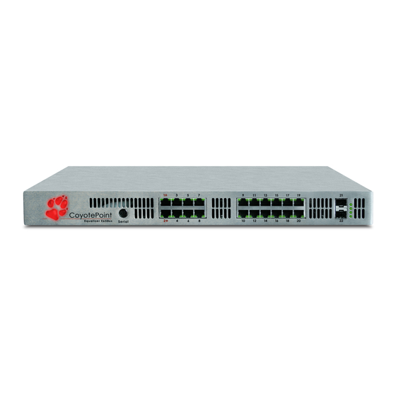
VLAN. Initially, ports 1 and 2 on the front panel are configured for the Default VLAN and all other ports are unassigned. The figure below shows the initial port configuration of an E350GX or E450GX model Equalizer, both of which have 12 front panel ports; the E650GX with 22 ports is configured similarly. -
Page 33: Using Equalizer E350/450/650Gx In A Single Vlan Environment
Adding Equalizer to Your Network Using Equalizer E350/450/650GX in a Single VLAN Environment In a “single VLAN” or “single network” environment, the client systems, servers, Intranet and/or Internet all connect to Equalizer through a single VLAN (in many configurations, this equates to a single subnet, but may be a segment of a subnet, depending on the network topology). -
Page 34: Using Equalizer E350/450/650Gx In A Dual Vlan Environment
Chapter 1: Equalizer Overview Using Equalizer E350/450/650GX in a Dual VLAN Environment In a dual VLAN environment, the external clients, Intranet, and Internet connect to Equalizer through one VLAN, while servers are connected to Equalizer through a separate VLAN. Figure 11 shows an example. Figure 11 Example of an E450GX dual VLAN configuration As you can see in the example above, Equalizer has a management IP and cluster IP on the 172.16.0.x network, and is connected to the router for that VLAN on Port 1;... -
Page 35: Using Equalizer E350/450/650Gx In A Complex Vlan Environment
Adding Equalizer to Your Network Using Equalizer E350/450/650GX in a Complex VLAN Environment The Figure below shows an example of configuring Equalizer into a complex VLAN environment where servers (and clients) are located on several separate VLANs: Figure 12 Example of an E450GX complex VLAN configuration In the example above, Equalizer has a management IP and cluster IP on the 172.16.0.x network, and is connected to the router for that VLAN on Port 1;... -
Page 36: Link Aggregation
Chapter 1: Equalizer Overview Link Aggregation Equalizer E350GX models and above are equipped with two Gigabit network interface cards that are teamed together using Link Aggregation to provide up to 2 Gigabits of throughput when redundant links are used. Link aggregation is always enabled and is managed by Equalizer;... -
Page 37: Where Do I Go Next
Where Do I Go Next? In the sample failover configuration above, there is no single point of failure. If a router goes down, the other router takes over; if a link fails, requests are routed through another link. In this dual network configuration, the Equalizers communicate over both the internal and external subnets. - Page 38 Chapter 1: Equalizer Overview Equalizer Installation and Administration Guide...
-
Page 39: Installing And Configuring Equalizer Hardware
Chapter 2: Installing and Configuring Equalizer Hardware This chapter contains all the information you need to get your Equalizer out of the box and onto your network: Before You Turn Equalizer On for the First Time .................40 Stepping Through the Hardware Installation ..................40 Setting Up a Terminal or Terminal Emulator ..................41 Serial Connection ..........................41 Performing Basic Equalizer Configuration ...................41... -
Page 40: Before You Turn Equalizer On For The First Time
Chapter 2: Installing and Configuring Equalizer Hardware Before You Turn Equalizer On for the First Time The first step in setting up Equalizer is to connect it to the local area network and a power source. Once you have installed Equalizer, you need to configure it as described in Chapter 3, “Configuring Equalizer Hardware”. Please review the warnings located in Appendix I , Additional Requirements and Specifications, on page 317 for precautions you must take before installing your Equalizer hardware. -
Page 41: Setting Up A Terminal Or Terminal Emulator
Setting Up a Terminal or Terminal Emulator Setting Up a Terminal or Terminal Emulator After the Equalizer hardware, you need to directly connect a terminal to Equalizer to complete the hardware configuration. Serial Connection When you set up Equalizer for the first time, you must use a serial connection in order to configure Equalizer’s network with the interface. -
Page 42: Starting To Configure Equalizer
On an E250GX system, continue with “Configuring External and Internal Interfaces on E250GX” on page 42. • On an E350GX, E450GX, and E650GX system, continue with “Configuring the Default VLAN on E350/450/650GX” on page 43. If the terminal display is not readable or not formatted properly, press and make sure that your terminal emulator is set for VT100 emulation. -
Page 43: Configuring The Default Vlan On E350/450/650Gx
“Testing Basic Connectivity” on page 49. Configuring the Default VLAN on E350/450/650GX On Equalizer models E350GX and above, the Equalizer’s Default VLAN (VLAN 1) Interface is configured first, and additional network configuration is performed by logging into the graphical Administrative Interface. To configure the Default VLAN (including the Equalizer’s hostname, default gateway, and DNS), follow these steps. -
Page 44: Setting The Time Zone
Chapter 2: Installing and Configuring Equalizer Hardware In the fields, respectively, specify the IP address and netmask for the Default IP address Netmask VLAN. When you’re finished, highlight and press Enter In the window, select option 6, ; then press . -
Page 45: Changing Equalizer's Console Password
Performing Basic Equalizer Configuration Changing Equalizer’s Console Password The console password is the password for the account, which automatically displays the Equalizer eqadmin Configuration Utility when you log in via or the serial port. The factory-installed password for this account is . -
Page 46: Shutting Down Equalizer
Chapter 2: Installing and Configuring Equalizer Hardware • If you chose : Enter the upgrade image URL provided to you by Coyote Point. The latest Option 1 CP FTP release of Equalizer software is always located at the following URL: ftp://ftp.coyotepoint.com/pub/patches/upgrades/latest/upgrade.tgz •... -
Page 47: Managing Remote Access To The Equalizer
Managing Remote Access to the Equalizer The new DNS settings take effect for all subsequent DNS queries, and will persist across system reboots. Managing Remote Access to the Equalizer Remote access, when enabled, provides a user account ( ) which allows you to log into Equalizer over a eqsupport Secure Shell (SSH) connection. -
Page 48: Configuring A Second Equalizer As A Backup (Failover)
Chapter 2: Installing and Configuring Equalizer Hardware http://www.chiark.greenend.org.uk/~sgtatham/putty/ • An SSH client running from a Windows Command window; for example, OpenSSH, which is freely available from: http://sshwindows.sourceforge.net/download/ • An SSH client running from a Cygwin window. Cygwin is a UNIX shell environment that includes versions of many UNIX utilities, including SSH;... -
Page 49: Testing Basic Connectivity
Testing Basic Connectivity To use geographic load balancing with firewalled networks, you need to configure the firewalls so that the following occurs: • Equalizer sites communicate with each other on UDP ports 5300 and 5301. The firewall must allow traffic on these ports to pass between Envoy sites. - Page 50 Chapter 2: Installing and Configuring Equalizer Hardware Equalizer Installation and Administration Guide...
-
Page 51: Using The Administration Interface
Chapter 3: Using the Administration Interface Use Equalizer’s HTML-based Administration Interface to perform the monitoring and administrative tasks described in the subsequent chapters of this guide. This chapter contains the following sections that show you how to log in and configure access to the interface: Logging In and Navigating the Administrative Interface ..............52 Logging In ............................52 Navigating Through the Interface ......................53... -
Page 52: Logging In And Navigating The Administrative Interface
Chapter 3: Using the Administration Interface Logging In and Navigating the Administrative Interface The Equalizer Administration Interface can be opened in any Javascript-enabled browser. Two default logins are provided: the login provides read-only access to the interface, and the login lets you view and edit the look touch configuration. -
Page 53: Navigating Through The Interface
Logging In and Navigating the Administrative Interface Click the button to log into Equalizer. The screen of the Administrative Interface is displayed, as login Home shown on the following page. Figure 15 The Home Screen of Equalizer’s Administration Interface Navigating Through the Interface The Equalizer Administration Interface (see Figure 15) is divided into three major sections: The left side of the screen displays a hierarchical list of objects, as explained below. - Page 54 Chapter 3: Using the Administration Interface • Click the plus sign next to a cluster name to open a list of currently defined servers and (for Layer 7 clusters) a list of Match Rules. • Click a cluster, server, or match rule name to open the management tabs for that object. •...
-
Page 55: Managing Access To Equalizer
Managing Access to Equalizer Managing Access to Equalizer You can control the IP addresses and protocols on which the web-based Administrative Interface (the ‘GUI’ or graphical user interface) is available, and the IP addresses over which SSH (Secure Shell) access to Equalizer is permitted. -
Page 56: Updating The Administration Interface Certificate
Chapter 3: Using the Administration Interface Updating the Administration Interface Certificate The Administration Interface is delivered with a default SSL certificate for https//: connections. Clients use this certificate to authenticate a connection with the interface. You can replace this certificate by doing the following: Log in to Equalizer using a login that has add/del access on global parameters (see “Logging In”... -
Page 57: Objects And Permissions
Managing Multiple Interface Users Objects and Permissions The following table shows the permissions and objects defined on Equalizer: Permissions Objects none global parameters read write cluster parameters add/del The permission set on the object specifies the user’s permission on all clusters with their permission set to none (the default), unless a different permission is set on the cluster. - Page 58 Chapter 3: Using the Administration Interface none The user cannot view, modify, or delete the object. For global parameters: the user cannot view any of the global parameter tabs displayed when you click on Equalizer in the left frame. For clusters: the left frame and all global tabs display only clusters that the user has been given explicit permission to view by assigning a higher permission to those clusters.
-
Page 59: Viewing Or Modifying Login Permissions
Managing Multiple Interface Users Viewing or Modifying Login Permissions To view or modify the permissions for a login, do the following: Log into the Administrative Interface using a login that has at least read access for global parameters (see “Logging In” on page 52). Select . -
Page 60: Adding A Login
Chapter 3: Using the Administration Interface ALL specifies the minimum permission the user has on all clusters below. Below ALL is a line for each cluster that specifies the permission that the cluster permissions user has on that cluster. If the permission on the cluster is to the left of the permission given for ALL, then the ALL permission applies to the cluster instead. -
Page 61: Deleting A Login
Entering Names for Equalizer Objects Select the desired . See the section “Objects and permission to modify system parameters and users Permissions” on page 57 for help. Select the desired . See the section “Objects and Permissions” on page 57 for help. cluster permissions Select to save the user definition. - Page 62 Chapter 3: Using the Administration Interface Equalizer Installation and Administration Guide...
-
Page 63: Equalizer Network Configuration
Chapter 4: Equalizer Network Configuration VLAN Basics ............................64 Configuring VLANs on Equalizer ......................65 Configuring VLANs Using the VLAN Wizard ..................66 Adding a VLAN Using the Add VLAN Command ................67 Modifying a VLAN ..........................68 Deleting a VLAN ..........................70 Managing Gigabit Switch Ports ......................71 Switch Administration Interface ......................72 Viewing Link Status ........................ -
Page 64: Vlan Basics
Chapter 4: Equalizer Network Configuration VLAN Basics Starting with Version 8.6, Equalizer models E350GX and above support tagged VLANs on both network interfaces. This section provides a basic technical introduction to VLAN technology. For an overview of the VLAN configurations supported on Equalizer, see “Equalizer E350GX, E450GX, E650GX Network Configuration”... -
Page 65: Configuring Vlans On Equalizer
Configuring VLANs on Equalizer A number of methods can be used to mitigate problems and threats associated with large broadcast domains, including broadcast filtering and physically separating large broadcast domains into smaller domains. The problem with these solutions is that the are typically implemented at the Network Layer (Layer 3), and require Layer 3 devices (such as routers and firewalls) to implement them. -
Page 66: Configuring Vlans Using The Vlan Wizard
Chapter 4: Equalizer Network Configuration The port numbers of the Untagged ports assigned to this VLAN. Untagged Untagged Ports ports can be assigned to exactly one VLAN. To see the detailed configuration for a VLAN, click on the icon on that row. See the section “Modifying a Modify VLAN”... -
Page 67: Adding A Vlan Using The Add Vlan Command
Configuring VLANs on Equalizer Adding a VLAN Using the Add VLAN Command Log into the Administrative Interface using a login that has access for global parameters (see “Logging write In” on page 52). Select Equalizer’s system name in the left frame and open the tab in the Networking >... -
Page 68: Modifying A Vlan
Chapter 4: Equalizer Network Configuration Enable any, all, or none of these check boxes to allow GUI access to Equalizer using the indicated protocols and IP addresses: HTTP on the VLAN IP. GUI http HTTPS on the VLAN IP. GUI https HTTP on the Failover IP. - Page 69 Configuring VLANs on Equalizer Highlight the route you want to change in the table and select the icon . The screen is Modify Modify VLAN displayed: Edit the values shown as desired: A descriptive name for the VLAN; must begin with an alphabetic Name character.
-
Page 70: Deleting A Vlan
Chapter 4: Equalizer Network Configuration When enabled, Equalizer perform failover health check probes using Use IP for Failover the VLAN IP of the peer Equalizer on this VLAN. If this check box is not enabled, then failover will not occur if connectivity between the Heartbeat failover peers on this VLAN is lost. -
Page 71: Managing Gigabit Switch Ports
Managing Gigabit Switch Ports Managing Gigabit Switch Ports This section does not apply to the E250 All Equalizer models have two Ethernet adapters on the motherboard. The switches on the front panel are and to legacy connected to both adapters. This allows any switch port to be configured to work with either adapter. E350si and In the default configuration, switch ports #1 &... -
Page 72: Switch Administration Interface
Chapter 4: Equalizer Network Configuration Switch Administration Interface interface allows you to easily view and modify the configuration of each port on Switch Configuration Equalizer’s front panel. Click on Equalizer in the left frame, and then click Status > Networking Configuration the right frame to display the tab: Switch Configuration... -
Page 73: Editing Port Settings
Managing Gigabit Switch Ports The port setting displayed in the mouseover popup are explained in the table below. Port Status Displays Active if the port has an active link, No Link if not. If the port is Active, this is the current port speed. If there is No Link, this is Port Speed the highest speed that can be negotiated, or the forced speed setting. -
Page 74: Commiting And Applying Switch Port Configuration Changes
Chapter 4: Equalizer Network Configuration When is set to , the popup looks like this: Autonegotiation Select Setting allows you to set a specific speed and duplex to be negotiated with the device on Autonegotiation Select the other end of the connection to this port. Only this speed and duplex combination is advertised for autonegotiation. -
Page 75: Switch Interface Usage Scenarios
Managing Gigabit Switch Ports Switch Interface Usage Scenarios Some suggestions for using the new switch interface: • In a single network configuration, the two external VLAN ports are unused. Ports #1 & 2 can be re- configured as part of the internal VLAN, adding two more server ports. •... -
Page 76: Configuring Static Routes
Chapter 4: Equalizer Network Configuration Configuring Static Routes Static routes are commonly used to specify routes to IP addresses via gateways other than the default. A default gateway is specified when you configure Equalizer via the eqadmin character based interface. If you need to access systems on a subnet that cannot be reached via this gateway, then you need to specify a static route to those systems through the gateway for that subnet. -
Page 77: Modifying A Static Route
Configuring Static Routes Click on the icon . The screen appears: Add New Route Figure 21 The add new route screen Enter the parameters for the route, and select . You are returned to the table, which now commit Static Routes displays the route you added. -
Page 78: Configuring Servers On Your Network
Chapter 4: Equalizer Network Configuration Configuring Servers on Your Network Configuring Routing on Servers In configurations where the cluster option is enabled, you should configure your servers so that Equalizer spoof gateways the packets the servers send to clients. In most cases, the easiest way to do this is to specify an IP address on Equalizer as the server default gateway in its routing tables. - Page 79 Configuring Servers on Your Network Figure 22 Example single VLAN configuration with local and remote servers The configuration in Figure 22 is an example of a single VLAN configuration, where Equalizer communicates with all servers and clients via the same subnet. The example cluster shown above contains three servers, two on the local 10.0.0.0 subnet, and one on another subnet.
- Page 80 Chapter 4: Equalizer Network Configuration Equalizer Installation and Administration Guide...
-
Page 81: Configuring Equalizer Operation
Chapter 5: Configuring Equalizer Operation This chapter describes the global parameters, resources, and procedures that you can use to specify Equalizer’s operating characteristics and perform system maintenance tasks: Licensing Equalizer ..........................82 Requesting a License Online ......................82 Requesting a License Offline ......................84 Modifying Global Parameters .........................85 Global Probe Parameters ........................85 Global Networking Parameters ......................87... -
Page 82: Licensing Equalizer
Chapter 5: Configuring Equalizer Operation Licensing Equalizer You must register and license your Equalizer before performing any other configuration using the Equalizer Administration Interface (described in Chapter 3, “Using the Administration Interface”). The License Manager helps you register and request a license, as well as view your current license information. You’ll need to request a license if: •... - Page 83 Licensing Equalizer The top section of the screen shows the following information for an already licensed system: license status Equalizer product model number. Displays product “unlicensed” if the system is not licensed or the current license is invalid. Lists any add-on products (such as Envoy) that are feature enabled by your current license.
-
Page 84: Requesting A License Offline
Chapter 5: Configuring Equalizer Operation Requesting a License Offline If your Equalizer is not currently connected to the Internet or if DNS is not configured for Equalizer, then you will need to request a license offline. To do this, follow this procedure: Follow Steps 1 through 3 of the procedure above. -
Page 85: Modifying Global Parameters
Modifying Global Parameters Modifying Global Parameters Global or System Parameters are divided into two tabs, Probes and Networking. Most clusters will work with default values on these tabs. To view or modify the default global parameter values: Log into the Administrative Interface using a login that has add/del access for global parameters to add, remove, and update parameters;... - Page 86 Chapter 5: Configuring Equalizer Operation The number of seconds between evaluation of all Smart Events for all event interval clusters. The default is 15 seconds. See “Configuring Smart Events” on page 161. The minimum time in seconds (default is 10) between successive TCP probes of servers by the probe daemon.
-
Page 87: Global Networking Parameters
Modifying Global Parameters Global Networking Parameters Selecting displays the global cluster networking parameters. These settings Equalizer > Clusters > Networking apply to all clusters of the appropriate type (Layer 4 or Layer 7 or both) as indicated in the table: The global networking parameters are described below: Applies to L7 clusters and is the amount of memory in kilobytes reserved by each L7 proxy process to store outgoing data before it is... - Page 88 Chapter 5: Configuring Equalizer Operation The length of time that a partially open or closed Layer 4 connection is maintained. If a client fails to complete the TCP connection termination stale timeout handshake sequence or sends a SYN packet but does not respond to the server’s SYN/ACK, Equalizer marks the connection as incomplete.
- Page 89 Modifying Global Parameters If your servers are on a network the outside world cannot reach, consider enabling Equalizer’s passive FTP translation option. This option passive FTP translation causes the Equalizer to rewrite outgoing FTP PASV control messages from the servers so they contain the IP address of the virtual cluster rather than that of the server.
-
Page 90: Setting Up A Failover Configuration
Chapter 5: Configuring Equalizer Operation Setting Up a Failover Configuration You can set up two Equalizer GX systems in a hot backup, or failover, configuration. In such a configuration, one of the systems handles incoming requests (the primary system), while the other (the backup system) waits for a failure to occur and automatically takes over if the Equalizer that is currently handling requests fails. -
Page 91: Failover Between Different Hardware & Software Versions
Since different Equalizer models and software revisions have varying configuration parameters, we recommend that you use the same model Equalizer hardware (e.g., E350GX, E450GX, etc.) and the same version of the EQ/OS software (e.g., 8.6.0a) for both systems in the failover pair. This is recommended because Equalizer by default maintains the same configuration files on both systems in a failover pair (so that you don’t need to manually update... -
Page 92: Using A Gx And An 'Si' In Failover With Version 8.6
Chapter 5: Configuring Equalizer Operation formats, we do not want configuration transfers to be performed between the peers. This means that changes made to the Equalizer configuration will need to be performed on both peers. As stated above, the is not used when one peer is running 8.5 and one is running 8.6. If the peer Peer Signature running Version 8.5 is subsequently upgraded to Version 8.6, the newly upgraded system will remain in the ‘... - Page 93 Setting Up a Failover Configuration • GUI access • SSH access Do the following on both failover systems: Click on the Equalizer system name in the left frame and then open the Networking > VLAN Configuration tab in the right frame. Use the Modify button in the column of the table to examine each VLAN.
-
Page 94: Enabling Failover Using The Failover Tabs
Chapter 5: Configuring Equalizer Operation Follow the directions on the screen to copy the peer signature of the other Equalizer into the Connect to Peer text box displayed. Click the button to continue. next On the screen: Set Peer Names and Primary Peer Enter names for both peers (or accept the defaults provided). - Page 95 Setting Up a Failover Configuration • Failover IP (must be provided on all VLANs for failover to work) • GUI access • SSH access Do the following on both failover systems: Click on the Equalizer system name in the left frame and then open the Networking >...
- Page 96 Chapter 5: Configuring Equalizer Operation Time in seconds (default: 0.5) to wait for a connection attempt to the connection timeout other peer to succeed before timing out. Time in seconds (default: 5.0) between successive heartbeat checks of probe interval the peer. When either the or the occurs on the backup system, that counts as one...
- Page 97 Setting Up a Failover Configuration Signature The unique identifying signature for this Equalizer. For each currently defined VLAN on this Equalizer, the VLAN IP for the VLAN is listed. If you need to make any VLAN name changes to the VLANs defined, use the VLAN Configuration button at the bottom of the dailog.
- Page 98 Chapter 5: Configuring Equalizer Operation Open the tab to update the default failover timer settings, if necessary. Make sure that these match the Timing settings you chose in Step 5 on page 95. If you make any changes, click commit 10.
-
Page 99: Modifying The Failover Configuration
Setting Up a Failover Configuration 12. Enter the following information for the Peer Equalizer A unique name for the other failover peer. We suggest “eq_” followed Equalizer Name: by the IP address of the Default VLAN on the peer Equalizer, but any name can be used. -
Page 100: Re-Enabling Failover After Disabling
Chapter 5: Configuring Equalizer Operation try to assume primary role and continously reboot. For this reason, you can disable failover on both systems as shown below. Note that, as soon as you disable failover on one failover peer, both peers will go into (as shone standalone mode on the... -
Page 101: Clearing The Failover Configuration
Setting Up a Failover Configuration If one of the Equalizers in the failover pair was shut down when failover was disabled or cleared, power on that Equalizer now. On the Equalizer you powered up in the previous step, or the Equalizer that had the lower configuration file number in Step 2: Click on the other Equalizer’s peer name at the top of the left frame tree. - Page 102 Chapter 5: Configuring Equalizer Operation # cp /var/eq/eq.conf /tmp Edit the file /tmp/eq.conf: # ee /tmp/eq.conf [The vi editor may also be used.] Remove the stanza from the file -- that is, remove all the text between the keyword at interface interface the top of the file and the curly brace that ends the interface stanza.
-
Page 103: Managing System Time And Ntp
Managing System Time and NTP Managing System Time and NTP Through Equalizer’s Administrative Interface, you can: • set the time zone • set the system date and time • set up to three Network Time Protocol (NTP) servers, and enable or disable synchronization with these servers NTP is a protocol designed to synchronize the clocks of computers over a network. -
Page 104: Selecting An Ntp Server
Chapter 5: Configuring Equalizer Operation To manage system time on Equalizer, follow this procedure: Log into the Administrative Interface using a login that has add/del access for global parameters (see “Logging In” on page 52). Select Equalizer > Maintenance > System Time Figure 25 The System Time tab To set the time zone, make a selection from the drop down box in the section, and select the... - Page 105 Managing System Time and NTP pool servers are specified by geography. The following table shows the naming convention for servers specified by continent: Table 26: Worldwide pool.ntp.org Asia asia.pool.ntp.org Europe europe.pool.ntp.org North America north-america.pool.ntp.org Oceania oceania.pool.ntp.org South America south-america.pool.ntp.org To use the continent-based NTP pool servers for Europe, for example, you could specify the following pool servers in Equalizer’s time configuration screen: 0.europe.pool.ntp.org 1.europe.pool.ntp.org...
-
Page 106: General System Maintenance
Chapter 5: Configuring Equalizer Operation General System Maintenance tab contains buttons for the system maintenance tasks described in the Equalizer > Maintenance > General following sections: Saving or Restoring Your Configuration ..................106 Using a Backup Archive Created on Another Equalizer............106 Backing Up Your Configuration .................... -
Page 107: Restoring A Saved Configuration
General System Maintenance When prompted, specify the location and filename to use for the backup archive. The default backup archive name is of the form hostname-mm.dd.yyyy-HH.MM.bkp, where hostname is the Equalizer system name, mm is the month, dd is the day, yyyy is the year, HH is hours and MM is minutes. Click to save the backup archive. -
Page 108: Rebooting Equalizer
Chapter 5: Configuring Equalizer Operation Rebooting Equalizer Rebooting Equalizer shuts it down cleanly and then restarts the system. To reboot the Equalizer: Log into the Administrative Interface using a login that has access for global parameters (see “Logging add/del In” on page 52). Select . - Page 109 General System Maintenance Do one of the following: • Click to connect to the Coyote Point FTP server to download the upgrade image. Coyote Point FTP Server • Click to connect to a local FTP server, to which you have already downloaded the User FTP Server upgrade image from the Coyote Point FTP server.
- Page 110 Chapter 5: Configuring Equalizer Operation Equalizer Installation and Administration Guide...
-
Page 111: Administering Virtual Clusters
Chapter 6: Administering Virtual Clusters Working with Virtual Clusters ......................112 Adding a Layer 7 Virtual Cluster ......................113 Modifying a Layer 7 Virtual Cluster ....................114 Adding a Layer 4 Virtual Cluster ......................121 Modifying a Layer 4 Virtual Cluster ....................122 Deleting a Virtual Cluster .........................126 Copying an Existing Virtual Cluster ....................126 Configuring a Cluster’s Load-Balancing Options ................127 Equalizer’s Load Balancing Policies ....................127... -
Page 112: Working With Virtual Clusters
Chapter 6: Administering Virtual Clusters Using IPMI to Power Servers On/Off ....................166 Complex Smart Event Expressions ....................166 Managing Smart Events ........................167 Using the Smart Event Expression Editor ..................168 Smart Event Examples ........................169 Configuring Direct Server Return (DSR) .....................177 Configuring Servers for Direct Server Return ..................179 Testing Virtual Cluster Configuration ....................182 Testing Your Basic Configuration .......................182 Working with Virtual Clusters... -
Page 113: Adding A Layer 7 Virtual Cluster
Working with Virtual Clusters L4 UDP clusters are appropriate for connectionless (stateless) applications, such as DNS, TFTP, Voice over IP (VoIP), and streaming applications -- any application that exchanges short packets with many clients, and where dropped packets are preferred to delayed packets (i.e., the highest possible network performance is required). -
Page 114: Modifying A Layer 7 Virtual Cluster
Chapter 6: Administering Virtual Clusters Modifying a Layer 7 Virtual Cluster The configuration tabs for a cluster are displayed automatically when a cluster is added to the system, or by selecting the cluster name from the left frame Configuration Tree. HTTP and HTTPS clusters parameters are divided among the following tabs: •... -
Page 115: Layer 7 Probes Tab
Working with Virtual Clusters Layer 7 Probes Tab The port on the Equalizer to be used to for all TCP and ACV server health check probes for this cluster. The port specified here becomes the default probe port used when a new server is added to the cluster. By default, the probe port field is set to zero and the Equalizer uses the Layer 7 port field value for the probe port when a new server is created. -
Page 116: Layer 7 Persistence Tab
Chapter 6: Administering Virtual Clusters Layer 7 Persistence Tab Please see “Enabling Persistent Server Connections” on page 129 for a discussion of server persistence on Equalizer. The cookie age sets the time, in seconds, over which the client browser maintains the cookie (0 means the cookie never expires). After the specified cookie age number of seconds have elapsed, the browser deletes the cookie and any subsequent client requests will be handled by Equalizer’s load-balancing... -
Page 117: Lb Policy Tab
Working with Virtual Clusters LB Policy Tab On this tab, choose a load balancing for the cluster: policy responsiveness For all cluster protocols, choose the appropriate load-balancing policy to be used by this cluster. Choose from round robin (default), static weight, policy adaptive, fastest response, least connections, server agent, and custom. -
Page 118: Layer 7 Networking Tab
Chapter 6: Administering Virtual Clusters Layer 7 Networking Tab The parameters in the tab affect: Networking • the amount of memory Equalizer allocates for data buffers and HTTP headers • the connections between clients and Equalizer • the connections between Equalizer and the servers in virtual clusters The amount of memory in kilobytes reserved by each Layer 7 proxy process to store outgoing data before it is placed on the network interface. -
Page 119: Layer 7 Security > Certificates Tab (Https Only)
Working with Virtual Clusters Specifies the mime-types that will be compressed when the compress flag is enabled for the cluster (see “Layer 7 Required Tab” on page 114). The value of this parameter is a string (maximum length: 512 characters) with valid mime-type names separated by a colon (:). -
Page 120: Layer 7 Security > Ssl Tab (Https Only)
Chapter 6: Administering Virtual Clusters • upload an SSL certificate that clients will use to validate a connection to an HTTPS cluster (a cluster certificate) • upload an SSL certificate for Equalizer to use to validate clients that request connections to HTTPS clusters certificate) client See “Using Certificates in HTTPS Clusters”... -
Page 121: Adding A Layer 4 Virtual Cluster
Note that if SSL processing is done in software (as on the E250GX and E350GX), then newer clients that contain the fix for CVE-2009-3355 will be able to renegotiate SSL sessions. When enabled, forces Equalizer to pass responses from an HTTPS cluster’s servers without rewriting them. -
Page 122: Modifying A Layer 4 Virtual Cluster
Chapter 6: Administering Virtual Clusters For L4 UDP and L4 TCP protocol clusters, a port range can be defined using the start port and end port fields. These are the ports on the Equalizer to be used to send traffic to the servers in the cluster. Port ranges allow Equalizer users to create a single cluster to control the traffic for multiple, contiguous ports. - Page 123 Working with Virtual Clusters For L4 UDP and L4 TCP protocol clusters, a port range can be defined using the start port and end port fields. These are the ports on the Equalizer to be used to send traffic to the servers in the cluster. Port ranges allow Equalizer users to create a single cluster to control the traffic for multiple, contiguous ports.
-
Page 124: Layer 4 Probes Tab
Chapter 6: Administering Virtual Clusters Layer 4 Probes Tab The port on the Equalizer to be used to for all TCP and ACV server health check probes for this cluster. The port specified here becomes the default probe port used when a new server is added to the cluster. By default, the probe port field is set to zero and the Equalizer uses the Layer 4 start port field value for the probe port when a new server is created. -
Page 125: Layer 4 Persistence Tab
Working with Virtual Clusters Layer 4 Persistence Tab sticky time is the number of seconds that Equalizer should “remember” connections from clients. Valid values are from 0 (which disables sticky sticky time connections) to 1073741823 seconds (or over 34 years). For more information, refer to “Enabling Sticky Connections”... -
Page 126: Deleting A Virtual Cluster
Chapter 6: Administering Virtual Clusters Deleting a Virtual Cluster Deleting a cluster with servers assigned to it also deletes the server definitions as well. To delete a cluster, follow these steps: Log into the Administrative Interface using a login that has access for global parameters (see “Logging add/del In”... -
Page 127: Configuring A Cluster's Load-Balancing Options
Configuring a Cluster’s Load-Balancing Options Enter the ip address, which is the dotted decimal IP address of the cluster. new cluster ip The IP address of the cluster is the address (for example, 199.146.85.0) that clients use to connect to the cluster. Enter the numeric port number on the Equalizer to be used for traffic between the clients and the cluster. -
Page 128: Equalizer's Load Balancing Response Settings
Chapter 6: Administering Virtual Clusters Equalizer might not dispatch new requests to that server even if that server’s response time is the fastest in the cluster. • least connections load balancing dispatches the highest percentage of requests to the server with the least number of active connections. -
Page 129: Enabling Persistent Server Connections
Configuring a Cluster’s Load-Balancing Options statistics. You can also customize server agents to report on server resource availability; then Equalizer can stop sending requests to a server if a database or other vital resource is unavailable. Note – When you configure a cluster to use server agents, each server in the cluster must run a server agent daemon, so that the agent can provide status information to the Equalizer. -
Page 130: Enabling Cookies For Persistent Connections
Chapter 6: Administering Virtual Clusters With the option, you can configure Equalizer to direct requests from a client to the same server inter-cluster sticky on any available port that has a current persistent connection in any cluster. When Equalizer receives a client request for a Layer 4 cluster with inter-cluster sticky enabled and the client does not have a sticky record for the cluster, then Equalizer will check other clusters that have inter-cluster sticky enabled for a sticky record for the same client and server -- but on a different server port than the one originally used in the client request. - Page 131 Configuring a Cluster’s Load-Balancing Options For example, before HTTP 1.1, if a browser wished to retrieve the file index.html from the server , the browser would take the following actions: www.coyotepoint.com Browser opens TCP connection to www.coyotepoint.com Browser sends request to server “GET /index.html”. Server responds with the content of the page (a bunch of HTML).
- Page 132 Chapter 6: Administering Virtual Clusters Requests in a single once only enabled once only disabled keep-alive connection First Request If request contains a cookie and If request contains a cookie and there is no match rule hit, send there is no match rule hit, send request to the server in the request to the server in the cookie.
-
Page 133: Enabling Both The Once Only And Always Options
Configuring a Cluster’s Load-Balancing Options flag is enabled by default when adding an L7 cluster. In general, it is more efficient to enable once only once ; but, in situations where load balancing decisions need to be made for every request or where any of the above only effects are undesirable, should be disabled. -
Page 134: Enabling Once Only And Compression
Chapter 6: Administering Virtual Clusters properly on the client. If, for example, a server sends an HTTP redirect using the header, this URL most Location: likely will include the protocol. Equalizer rewrites this response so that the URL uses http:// https: For server connections that contain multiple server responses, the setting of the flag determines whether... -
Page 135: Enabling Acv
Configuring a Cluster’s Load-Balancing Options User requests connection to server. > telnet www.myserver.com 80 Telnet indicates connection is established. Connected to www.myserver.com User sends request for HTML page. > GET /index.html Server responds with requested page. <HTML> <TITLE>Welcome to our Home Page</TITLE> </HTML>... -
Page 136: Https Header Insertion
Chapter 6: Administering Virtual Clusters Equalizer sends this string to each server in the cluster to request verifiable data. Note – When you set up a L7 cluster and add a probe string, \r\n (that is, a “carriage return” followed by a “line feed”) is automatically added to the end of the string. -
Page 137: Performance Considerations For Https Clusters
The E650GX and E450GX include the Xcel SSL Accelerator Card. Equalizer models without Xcel (E250GX and E350GX) performa all SSL processing in software using the system CPU. Equalizers with Xcel perform all SSL processing using the dedicated processor on the Xcel card. This allows the system CPU to concentrate on non-SSL traffic. -
Page 138: Providing Ftp Services On A Virtual Cluster
Chapter 6: Administering Virtual Clusters noteworthy, however, that even when moving bulk data at 600Mbit/s, Xcel removes the entire load of HTTPS/SSL processing from the servers in the cluster. One final issue to be aware of is that Xcel supports only 3DES and RC4 encryption; it does not support AES. It also does not support SSL or TLS cipher suites that use ephemeral or anonymous Diffie-Hellman exchange (cipher suites whose names contain "EDH", "DHE", or "ADH"). - Page 139 Configuring a Cluster’s Load-Balancing Options • FTP data connections are automatically configured (internally) with a of one second. This is sticky time necessary to support the passive mode FTP data connection that most web browsers use. This means that there will be one sticky record kept for each FTP data connection. For an explanation of sticky records, see “Enabling Sticky Connections”...
-
Page 140: Managing Servers
Chapter 6: Administering Virtual Clusters Managing Servers The following sections discuss viewing, adding, and deleting servers, as well as server configuration options: The Server Table Server Software Configuration Adding a Server to a Cluster Modifying a Server Configuring Outbound NAT Adjusting a Server’s Initial Weight Setting Maximum Connections per Server Shutting Down a Server Gracefully... -
Page 141: Server Software Configuration
Managing Servers Status indicators for each server in the cluster: The server is responding to probes and is ready to receive traffic. The server is not responding to probes and no traffic is being routed to it. The server is responding to probes, and is either disabled (the server’s initial weight is set to 0) or the quiesce option is enabled. -
Page 142: Adding A Server To A Cluster
Chapter 6: Administering Virtual Clusters Adding a Server to a Cluster To add a server to a virtual cluster, follow these steps: Log into the Administrative Interface using a login that has access for the cluster (see “Logging In” on add/del page 52). - Page 143 Managing Servers If a port range has been defined for the Layer 4 cluster to which the server is being added, the field Server Port refers to the first port on which to start servicing the cluster’s port range. For example: Port Mapping Cluster Port Range Server Port...
-
Page 144: Modifying A Server
Chapter 6: Administering Virtual Clusters Modifying a Server The configuration tabs for a server are displayed automatically when a server is added to the system, or by selecting the server name from the left frame Configuration Tree. Log into the Administrative Interface using a login that has at least access for the cluster that contains the write server (see “Logging In”... -
Page 145: Configuring Outbound Nat
Managing Servers Sets the maximum number of permitted open connections for the server. Once this limit is reached, no more traffic is routed to the server until the number of open connections falls below this limit. This limit is max connections set by default to 0, which means that there is no maximum connections imit on the server. -
Page 146: Enabling Outbound Nat
Chapter 6: Administering Virtual Clusters In the default outbound NAT configuration, the Network Address Translation (NAT) daemon maps internal server IP addresses to Equalizer’s Default VLAN IP address (or the external interface IP address on the E250GX and legacy ‘si’ systems). You can also configure outbound NAT for individual servers, so server responses appear as if they came from the cluster IP address, instead of Equalizer’s external interface IP address. -
Page 147: Using Outbound Nat On A Server Ip In Multiple Clusters
Managing Servers Using Outbound NAT on a Server IP in Multiple Clusters Servers are identified in the NAT daemon configuration file by their IP addresses. If a server IP address is listed more than once in the file, it is the last NAT setting listed in the file that takes effect for that server IP. This means that: •... -
Page 148: Setting Initial Weights For Mixed Clusters
Chapter 6: Administering Virtual Clusters the initial weight of one server to 110 and the other to 90. Fine-tuning server weights to match each server’s actual capability can easily improve your cluster’s response time by 5 to 10%. Note – A change to a server’s initial weight is reflected in cluster performance only after Equalizer has load balanced a significant number of new client requests for up to 30 minutes against the cluster in which the servers reside. -
Page 149: Maximum Connections Limits, Responders, And Hot Spares
Managing Servers Maximum Connections Limits, Responders, and Hot Spares When a maximum connections limit is set on all the servers in a cluster, it is often desirable to define either a responder or a hot spare server for the cluster, so that any attempted connections to the cluster that occur after the limit has been reached are directed to the responder or hot spare instead of being refused or sent max connections to the server anyway because of a persistent connection. -
Page 150: Removing A Layer 7 Server From Service
Chapter 6: Administering Virtual Clusters Connections that are already established continue to exist until the client and server application end them or they time out because they are idle. To shut down servers in a generic TCP or UDP (L4) cluster, you can set the server’s weight to zero and wait for the existing connections to terminate. - Page 151 Managing Servers Log into the Administrative Interface using a login that has access for the cluster that contains the add/del server (see “Logging In” on page 52). If necessary, shut the server down gracefully before taking it out of service, as shown in the section “Shutting Down a Server Gracefully”...
-
Page 152: Automatic Cluster Responders
Chapter 6: Administering Virtual Clusters Automatic Cluster Responders Responders are not A Responder is a server-like object that can be associated with a Match Rule. If an incoming request matches a supported on E250 Match Rule expression and all of the servers specified in the Match Rule are down, a Responder definition in the model Match Rule (if present) tells Equalizer to send one of two automatic responses to the client: Equalizers... - Page 153 Automatic Cluster Responders To create a Responder, you can either: • Right-click on in the left frame and then select from the menu. Responders Add New Responder • Click on in the left frame and then select the icon in the table in the right frame. Responders dialog appears.
-
Page 154: Modifying A Responder
Chapter 6: Administering Virtual Clusters An optional POSIX-style regular expression that splits the incoming Regular request URL into variables that can be used for string replacement in the HTTP Redirect URL (see above). See the section “Using Expression Regular Expressions in Redirect Responders” on page 154. >... -
Page 155: Example 1 -- Https Redirect
Automatic Cluster Responders • parse the URL of an incoming request • break it down into separate strings (based on the positions of literal characters in the expression) • assign each string to a named variable These named variables can then be used in the URL field of the Redirect Responder. When the Responder replies to a client, it performs string substitution on the URL. -
Page 156: Example 2 -- Multi-Hostname Redirect
Chapter 6: Administering Virtual Clusters Clicking the button displays a popup that shows the effect of applying the to the URL: test Regex Test This Responder can be used in any cluster where a Redirect to an HTTPS cluster is desired. Example 2 -- Multi-Hostname Redirect Let’s assume that we have a set of ‘.com’... -
Page 157: Example 3 -- Directory Redirect
Automatic Cluster Responders Clicking the button displays a popup that shows the effect of applying the to the URL: test Regex Test It should be noted that this example will not work for requests with destination URLs specified with an IP address for a hostname (e.g., ‘... -
Page 158: Using Responders In Match Rules
Chapter 6: Administering Virtual Clusters We can then use these variables in the URL field as shown in the following Responder configuration screen: Clicking the button displays a popup that shows the effect of applying the to the URL: test Regex Test This Responder can be used in a Match Rule in any cluster where a similar directory name based redirect is required. -
Page 159: Creating A Match Rule To Redirect All Traffic For A Specific Url
Automatic Cluster Responders Responder -- thus, if all the servers in the match rule are down, Equalizer drops the client connection to the Default cluster. In order to change the default behavior and supply a “sorry page” or redirect for a cluster, you need to add a new match rule that: •... -
Page 160: More Responder Examples
Chapter 6: Administering Virtual Clusters • matches any incoming request • selects none of the servers in the cluster • has a Responder selected Redirect For example, let’s say that we want all traffic to a cluster that uses the URL to be http://cluster/special/ redirected to... -
Page 161: Configuring Smart Events
Configuring Smart Events Configuring Smart Events Smart Events are not Equalizer’s feature allows administrators to define that automate common supported Smart Control Smart Events on E250 administrative functions based on pre-set threshold values for system parameters and statistics. For example, you model could specify that when the number of active servers in a particular cluster falls below a certain number, then a Equalizers... - Page 162 Chapter 6: Administering Virtual Clusters Figure 31 Smart Event Trigger Functions and Variables All or Trigger Description Functions & Variables only A variable whose value is the current number of active active_servers servers for a cluster. Returns the number of active connections for the server connection_server (server) selected from the drop-down box.
-
Page 163: Smart Event Action Functions And Variables
Configuring Smart Events All or Trigger Description Functions & Variables only Returns the current dynamic weight of the server selected from the drop-down box; between 0 and 200. 0 means weight_server (server) that no new requests are being routed to the server, essentially disabling the server. - Page 164 Chapter 6: Administering Virtual Clusters All or Action Description Functions & Variables only Sends a power off command to a server with a Baseboard ipmi_poweroff (BMC IP, Management Controller (BMC) and Intelligent Platform BMC username, Management Interface (IPMI) driver installed and BMC password, configured.
-
Page 165: Smart Event Operators
Configuring Smart Events Smart Event Operators The functions in the tables above can be combined using the operators shown below: Operators Description = = , > , < numeric equals, greater than, less than || , && , ! logical OR, AND, NOT group two or more functions and operators remove the selected function, variable, or operator from the expression... -
Page 166: Complex Smart Event Expressions
Chapter 6: Administering Virtual Clusters In order to use an IPMI function to control a server, the server must have a Baseboard Management Controller (BMC), a separate network interface that provides IPMI services. The BMC is usually enabled and configured via the system BIOS, which must be accessed when the system boots. -
Page 167: Adding A Smart Event
Configuring Smart Events for that cluster. The tab lists all the currently defined Smart Events for the cluster in a table; initially, Smart Events it is empty as shown below: ready blocked column lists the Smart Event name (supplied when the event is created). The column can be one Name Status... -
Page 168: Displaying Smart Event Statistics
Chapter 6: Administering Virtual Clusters A confirmation dialog is displayed. Click to delete the Smart Event. delete Displaying Smart Event Statistics To display statistics for a Smart Event, do one of the following: • Click on the Smart Event name in the left frame. (Use the expand control (plus sign) next to a cluster name to see all the Smart Events defined for the cluster). -
Page 169: Logging A Message When Server Count Is Low
Configuring Smart Events Logging a Message When Server Count is Low Let’s say we want to create a Smart Event for a cluster that prints a message to the Equalizer log any time there are fewer than 2 servers active in the cluster. To create this event: Right-click on a cluster name in the left frame and select from the popup menu. -
Page 170: Unquiescing A Server When Server Count Is Low
Chapter 6: Administering Virtual Clusters Unquiescing a Server When Server Count is Low Let’s say we have a cluster that has three servers, , and sv00 sv01 sv02 • We want to actively serve traffic, and to have the option enabled while the sv00 sv01 sv02... - Page 171 Configuring Smart Events When you finish typing the message, click . The field should now look like this: accept expression workbench 11. At the top of the popup window, click the Next icon ( Add New Event > 12. A confirmation screen appears that summarizes the new event. Click to save the new event.
-
Page 172: Using Ipmi To Conserve Server Resources
Chapter 6: Administering Virtual Clusters Using IPMI to Conserve Server Resources Smart Events with IPMI functions can be used for power management of server resources. For example, let’s say we have a cluster whose traffic can be handled during non-peak hours by two non-IPMI enabled servers -- these servers are always powered on. - Page 173 Configuring Smart Events • We’ll assume that can start serving traffic 180 seconds after it is powered on, and that it takes ipmi-server the same number of seconds to shut down completely, and use 180 seconds for the wait timer on ipmi01 the event actions.
- Page 174 Chapter 6: Administering Virtual Clusters Click the next icon ( > Construct the shown below using the expression editor controls: Event Action Click the next icon ( > Click to create the event. The object tree at left refreshes to display the new event. commit peak-off-ipmi01 Click on the new event name and open the...
- Page 175 Configuring Smart Events Click on the new event name and open the tab in the right frame. Use the expression editor to add Action an event wait timer for this event, as shown below: Click commit Right-click on the cluster name, and select from the popup menu: Add Event Type...
- Page 176 Chapter 6: Administering Virtual Clusters Do the above for each event in the cluster. When you are done, click on the cluster name in the left frame and open the tab in the right; the column in the table should display “ ”...
-
Page 177: Configuring Direct Server Return (Dsr)
Configuring Direct Server Return (DSR) Configuring Direct Server Return (DSR) In a typical load balancing scenario, server responses to client requests are routed through Equalizer on their way back to the client. Equalizer examines the headers of each response and may insert a cookie, before sending the server response on to the client. - Page 178 Chapter 6: Administering Virtual Clusters DSR can also be used in dual network mode, although this is a less common configuration than single network mode. Cluster IPs are on the external interface, and server IPs are on the internal interface. An example of a dual network mode DSR configuration is shown below.
-
Page 179: Configuring Servers For Direct Server Return
Configuring Direct Server Return (DSR) spoof causes Equalizer to spoof the client IP address when Equalizer routes a request to a server in a virtual cluster; that is, the IP address of spoof the client is sent to the server, not the IP address of the Equalizer. This flag must be enabled for DSR. -
Page 180: Configuring Windows Server 2003 And Iis For Dsr
Chapter 6: Administering Virtual Clusters Configuring Windows Server 2003 and IIS for DSR The basic procedure below also applies to Windows XP and other versions of Windows. Open Start > Control Panel and double-click Network Connections. Select View > Tiles. If a Microsoft Loopback Adapter is already listed, proceed to the next step. Otherwise, to install the loopback interface as follows: Open Start >... -
Page 181: Configuring A Loopback Interface On Other Systems For Dsr
Configuring Direct Server Return (DSR) lo:dsr Link encap:Local Loopback inet addr:cluster-ip Mask:255.255.255.255 UP LOOPBACK RUNNING MTU:16436 Metric:1 To configure an Apache 2.0 server for DSR, edit the server configuration file to add a directive for the Listen cluster IP (on many systems, the configuration file is found at /usr/local/etc/apache/httpd.conf). Look for the first line beginning with the Listen directive, and add another line that looks like this: Listen cluster-ip Where... -
Page 182: Testing Virtual Cluster Configuration
Chapter 6: Administering Virtual Clusters Testing Virtual Cluster Configuration After you have configured a virtual cluster and added servers, use a web browser (or just use telnet) to connect to each of the virtual clusters configured on the Equalizer from a system on your network. When you connect to a virtual cluster from the external test machine, Equalizer should send the request to one of the servers configured in the cluster, and you should see the output for that server. -
Page 183: Monitoring Equalizer Operation
Chapter 7: Monitoring Equalizer Operation System status information and performance statistics can be gathered and displayed from within the Equalizer Administrative Interface. Equalizer models E350 and above can also be monitored using standard Simple Network Management Protocol (SNMP) utilities: Displaying Equalizer System Information ...................184 Displaying General Cluster Status .......................185 Displaying the System Event Log ......................186 Displaying the Virtual Cluster Summary .....................187... -
Page 184: Displaying Equalizer System Information
Chapter 7: Monitoring Equalizer Operation Displaying Equalizer System Information The Equalizer Status screen is displayed when you log into the Administrative interface, and anytime by selecting Help > About Figure 36 Equalizer system information The Equalizer status screen displays information about Equalizer’s operation mode and overall status: The login name of the currently logged in user. -
Page 185: Displaying General Cluster Status
Displaying General Cluster Status internal address The IP address assigned to Equalizer’s internal interface. The current failover mode: standalone (no failover); initializing (the failover subsystem is coming up); primary (the system is the primary failover peer); failover mode or, backup (the system is the backup failover peer). Envoy geographic Envoy status: enabled (licensed) or disabled (not licensed). -
Page 186: Displaying The System Event Log
Chapter 7: Monitoring Equalizer Operation The cluster type: one of tcp_l4 (Layer 4 TCP), udp_l4 (Layer 4 UDP), Type http (Layer 7 HTTP), https (Layer 7 HTTPS). The cluster IP address. IP Address Port The cluster port. Status indicators for all servers in the cluster. Shows the number of servers in the following states: Up (responding to health check probes), Down (not responding to health check probes), Quiesced (not accepting Servers... -
Page 187: Displaying The Virtual Cluster Summary
Displaying the Virtual Cluster Summary Displaying the Virtual Cluster Summary Select to open the Virtual Cluster Summary. This table displays basic status Equalizer > Status > Cluster Summary and statistics for the currently configured virtual clusters, their associated servers, and Layer 7 match rules, as shown in the example below: Figure 39 Viewing cluster summary information Click on a cluster name to open the summary for that cluster. - Page 188 Chapter 7: Monitoring Equalizer Operation (Layer 4 clusters with a non-zero sticky time only): The number of inactive “sticky records” currently held by Equalizer. This equals the number of sticky Sticky records minus the number of Active connections (see above). See “Enabling Sticky Connections”...
-
Page 189: Displaying Global Connection Statistics
Displaying Global Connection Statistics Displaying Global Connection Statistics Click on the plus sign (+) next to in the left frame to display the following statistics: Connections The total number of Layer 4 connections processed since the last reboot. These are L4 processed connections that have been opened and data has passed over the connection. - Page 190 Chapter 7: Monitoring Equalizer Operation The number of Layer 7 connections that timed out L7 connections timed out because one of the connection timers (client timeout, connect timeout, or server timeout) expired. The number of bytes received in client requests. L7 request bytes from clients L7 response bytes to clients The number of bytes received in server responses.
-
Page 191: Displaying Cluster Statistics
Displaying Cluster Statistics The total number of input bytes from all server L7 http bytes selected for compression responses that were selected for compression. The total number of compressed bytes output from all L7 http compressed bytes output server responses. The approximate current compression ratio (bytes selected for compression divided by the compressed L7 http compression ratio... -
Page 192: Displaying Site Statistics
Chapter 7: Monitoring Equalizer Operation Displaying Site Statistics To display statistics for a Site in a GeoCluster, click on the Site name in the left frame object tree, and then select the tab in the right frame. The following statistics are displayed: Reporting >... -
Page 193: Plotting Global Performance History
Plotting Global Performance History Plotting Global Performance History Click on (or the configured Failover Peer Name for this Equalizer) in the left frame, and open the Equalizer tab in the right frame. Status > Plots Select one or more of the following statistics to plot (all statistics are reset on reboot): The average percent of non-idle CPU time over the CPU Utilization selected time period. -
Page 194: Plotting Server Performance History
Chapter 7: Monitoring Equalizer Operation The average service time of all of the servers in the cluster. The service time is the time it takes a server to start sending reply packets once it receives a client request. The average service time is a reasonable indication of the overall performance of the cluster. - Page 195 Plotting Server Performance History In the drop down box, use the keys and the left mouse button to select one or more of the following Ctrl Shift statistics to plot: The number of active connections on the server. Equalizer “smooths” the connection count using a sliding-window smoothing Active Connections algorithm before being plotted.
-
Page 196: Plotting Match Rule Performance History
Chapter 7: Monitoring Equalizer Operation The value that the server agent daemon returns. When queried, the server agent returns a value in the range -2 to 100. If you have not configured the cluster to use the server agent or the server agent daemon is not running on this server, the server agent value displayed is -2. -
Page 197: Plotting Geocluster Performance History
Plotting GeoCluster Performance History The time interval displayed in the plot. Sets the horizontal time Duration scale for the plot. For example, if 5 mins is selected, all the data collected over the last 5 minutes is displayed in the plot. The plot display is updated automatically with your settings the next time the display is refreshed. -
Page 198: Exporting Usage Statistics
Chapter 7: Monitoring Equalizer Operation The number of requests in which an agent failed to reply to No Agent Response Equalizer’s probes. The number of times that the target resource failed to respond during Resource Down the period plotted. The number of times the default site was chosen in response to a Default Chosen client query. - Page 199 Exporting Usage Statistics The average of the server agent values returned for all Agent servers in the cluster. The average number of active connections for all servers in Connections the cluster. The cluster load is calculated by adding together all current server load values for all servers in the cluster, and dividing by the number of currently active servers.
- Page 200 Chapter 7: Monitoring Equalizer Operation The computed load for the server. Server load as calculated by Equalizer is a measure of the request load on this server relative to the other servers in the cluster. The server load is a number between 0 and [100 times the number of servers in the cluster].
-
Page 201: Configuring Custom Event Handling
Configuring Custom Event Handling Configuring Custom Event Handling You can configure Equalizer to perform certain actions when a server fails or other critical events occur. You can forward Equalizer log information to another machine, and specify a command to run or email to be sent when a server event occurs. -
Page 202: Configuring Email Notification
Chapter 7: Monitoring Equalizer Operation When an event command is configured and one of the above events occurs, the command is executed and a one-line message describing the event that occurred is sent to the standard input of the specified command. This message can then be read and examined by the command to which it is passed. -
Page 203: Disabling Email Notification
Configuring Custom Event Handling Log into the Equalizer Administration Interface (see “Logging In” on page 52). Select Equalizer > Monitoring > Events In the section, enter the sender of the email in the field using the format required by email notification from your SMTP server. -
Page 204: Browsing Equalizer Configurations Using Snmp
Chapter 7: Monitoring Equalizer Operation Browsing Equalizer Configurations using SNMP SNMP is not The Simple Network Management Protocol (SNMP) is an internet standard that allows a management station to supported on E250 monitor the status of a device over the network. SNMP organizes information about the Equalizer and provides a model standard way to help gather that information. -
Page 205: Enabling The Snmp Agent
Browsing Equalizer Configurations using SNMP • IP address and port (or range) • Sticky time and cross cluster sticky • Cookie on or off Enabling the SNMP Agent The SNMP agent responds to outside SNMP requests, usually from an SNMP management station. To configure the SNMP agent, follow these steps from the Equalizer Administration Interface in Edit mode. -
Page 206: Setting Up An Snmp Management Station
Chapter 7: Monitoring Equalizer Operation Use the check boxes to enable the corresponding traps. The following table shows the traps that are enabled or disabled using the check boxes. This checkbox controls two traps, cpsSysEqServerDownEv and Enable server up/down cpsSysEqServerUpEv. Equalizer triggers these traps when it detects events either a server failure or a response from a failed server. -
Page 207: Siblings
Browsing Equalizer Configurations using SNMP The following is a summary description of the Equalizer MIB. The MIB source files contain detailed comments for each variable; these comments may also be displayed by the MIB browser when a variable is accessed. Siblings The main object that describes siblings is cpsSysEqSiblings. - Page 208 Chapter 7: Monitoring Equalizer Operation Equalizer Installation and Administration Guide...
-
Page 209: Using Match Rules
Chapter 8: Using Match Rules This chapter tells you all you need to know to create Layer 7 Match Rules that load balance requests based on the Match Rules content in the payload of the requests, as well as the header information and other request characteristics. are not supported Why Match Rules? ..........................208... -
Page 210: Why Match Rules
Chapter 8: Using Match Rules Why Match Rules? The ability to make load balancing decisions based on the content of a client request is what separates Layer 7 processing from the processing options available at Layer 4. For Layer 7 clusters, Match Rules provide fine-grained control over load balancing decisions based on the content of the client request. -
Page 211: Match Rule Processing
Why Match Rules? Figure 42 Conceptual Example of Match Rule Processing Most client requests are a mix of requests for text and graphics. Layer 7 processing without Match Rules (top diagram in Figure 42) balances requests across all the available servers in the cluster, so that each server will see a mix of text and graphics requests. -
Page 212: Match Rules, The Once Only Flag, And Cookies
Chapter 8: Using Match Rules This process applies even if all the servers selected for the match rule are unavailable. In this case, when the match rule expression matches the request and all the servers in the match rule server list are unavailable, no reply is sent to the client. -
Page 213: General Match Expressions And Match Bodies
General Match Expressions and Match Bodies General Match Expressions and Match Bodies A match rule consists of a match expression and a match body, which identifies the operations to perform if the expression is satisfied by the request. Match syntax is as follows: match name { expression } then { body } Each match has a name, which is simply a label. -
Page 214: Match Bodies
Chapter 8: Using Match Rules Various functions return true when their arguments match certain components of the request URI. Using the above request URI, for example, you could use several match functions: • pathname() returns true if its argument matches /somedir/somepage.html •... -
Page 215: Match Rule Definitions
General Match Expressions and Match Bodies Match Rule Definitions Match rules are defined in the file /var/eq/eq.conf with the definition of the cluster to which the match rule applies. A match rule as it appears in eq.conf looks like the following example: match ma01 { client_ip("10.0.0.19") } then {... -
Page 216: Managing Match Rules
Chapter 8: Using Match Rules Managing Match Rules The Administration Interface allows you to create and modify match rules, without requiring a detailed knowledge of the configuration language syntax used in the eq.conf file. The interface validates match rules before saving them so that all saved rules are syntactically correct. -
Page 217: The Default Match Rule
Managing Match Rules The Default Match Rule All Layer 7 clusters created via the Equalizer Administration Interface start with a single match rule (named Default ) that matches all requests and selects all servers. match Default { any() } then { servers = all;... -
Page 218: Creating A New Match Rule
Chapter 8: Using Match Rules is never processed. This effectively creates a new default match rule that you can configure with the desired load balancing options. Also note that some options in the match rule displayed in Figure 45 are only displayed for an HTTPS cluster, or on an Equalizer with GZIP compression enabled. - Page 219 Managing Match Rules The Match Rule tab is displayed. Configuration Figure 47 Match rule Configuration tab field displays the name of the rule before which the currently displayed rule is evaluated. By default, order a new rule is placed immediately before the Default rule. Change the placement of the new rule by choosing a rule from the list box.
- Page 220 Chapter 8: Using Match Rules From the drop-down list, select the match function and or expression with which you want to replace the selected part of the expression. Supply values for all arguments required by the function. To learn more about match functions, refer to “Match Functions”...
-
Page 221: Modifying A Match Rule
Match Functions Modifying a Match Rule To edit a match rule, follow these steps: Log into the Administrative Interface using a login that has write access for the cluster (see “Logging In” on page 52). In the left frame, click the name of the match rule to be changed. Make the desired changes to the match rule, as shown in the procedure in the previous section, starting at Step 5 on page 217. - Page 222 Chapter 8: Using Match Rules non-URI Match Function Description This function always evaluates to true. It writes the string argument to the Event Log for the cluster (View > Event Log). This function can be logically ANDed and ORed with other debug_message(string) functions to write debug messages.
- Page 223 Match Functions non-URI Match Function Description This function evaluates to true if the selected header is present header_regex(header, string) and if the string-valued argument string, interpreted as a regular expression, matches the associated header text. In addition to the functions in the preceding table, a set of functions is provided that allows you to process requests based on the various components of a request’s destination URI.
- Page 224 Chapter 8: Using Match Rules URI Match Function Description This function evaluates to true if the string argument is a prefix of the hostname portion of the URI path. The prefix of the hostname host_prefix(string) includes all text up to the first period (“www” in “www.example.com”).
-
Page 225: Match Function Notes
Match Functions URI Match Function Description This function evaluates to true if the string argument is a suffix of the filename_suffix(string) filename portion of the URI path. This function evaluates to true if the string argument is a substring of filename_substr(string) the filename portion of the URI path. -
Page 226: Considering Case In String Comparisons
Chapter 8: Using Match Rules makes sense to route the request to the (for example) down server, and have the client receive an appropriate error -- so that the request can be retried. If we instead were to skip a match rule because, for example, the server selected by the match rule is down, the request would be evaluated by the next match rule -- or the default match rule. -
Page 227: Https Protocol Matching
Match Functions Accept-Encoding If-Match Trailer Accept-Language If-Modified-Since Transfer-Encoding Authorization If-None-Match Upgrade Cache-Control If-Range User-Agent Connection If-Unmodified-Since Content-Length Max-Forwards Warning Cookie Pragma X-Forwarded-For Date Proxy-Authorization Expect Range HTTPS Protocol Matching Equalizer permits the construction of virtual clusters running the HTTPS protocol. HTTPS is HTTP running over an encrypted transport, typically SSL version 2.0 or 3.0 or TLS version 1.0. -
Page 228: Using Responders In Match Rules
Chapter 8: Using Match Rules Replaces the currently selected logical construct with the replace with self AND any current selection logically AND’ed with the “any()” function. Replaces the currently selected logical construct with the replace with self OR any current selection logically OR’ed with the “any()” function. Replaces the currently selected function or logical construct with the “any()”... -
Page 229: Parsing The Uri Using Match Rules
Example Match Rules Parsing the URI Using Match Rules In this example, we want to direct requests to a particular server based on the hostname used in the URI contained in the request. We want all requests for URIs that start with “support” to go to one server, and all other requests that do not match this rule to be load balanced across all servers in the cluster. - Page 230 Chapter 8: Using Match Rules Select the button to save your changes to the rule. commit support Equalizer Installation and Administration Guide...
-
Page 231: Changing Persistence Settings Using Match Rules
Example Match Rules Changing Persistence Settings Using Match Rules By default, a client request that matches a match rule expression is load balanced using the same load balancing parameters and options that are currently set on the cluster. This section shows you how to change load balancing parameters and flags in a match rule. - Page 232 Chapter 8: Using Match Rules Type “ ” into the text box. The dialog should now look like this: testexample.com hostname suffix Click continue In the field, disable both of the two check boxes to the right of the flag: servers and options persist Select the...
-
Page 233: Changing The Spoof (Snat) Setting Using Match Rules
Example Match Rules Changing the Spoof (SNAT) Setting Using Match Rules By default, Equalizer uses the client IP address as the source address in the packets it forwards to servers, and then translates the server IP in server responses to Equalizer’s cluster IP. This is commonly called a Half-NAT configurartion, since Equalizer is not performing Network Address translation (or NAT) on client requests. - Page 234 Chapter 8: Using Match Rules Click commit The new match rule is created and its tab is opened. Configuration In the field, click on expression any() In the dialog: Edit Match Rule Select from the drop-down box. replace with client_ip In the text box, specify a simple IP address (e.g., “192.168.0.240”), or an IP address in Classless Inter- Domain Routing (CIDR) notation (e.g., “192.168.0.0/24”) to specify an entire subnet.
- Page 235 Example Match Rules tab should now look similar to the example below: Configuration client_ip function all servers selected spoof option disabled At the bottom of the tab, click Configuration commit Clients whose IP addresses are selected by the new match rule should now be able to connect successfully to the cluster IP.
-
Page 236: Server Selection Based On Content Type Using Match Rules
Chapter 8: Using Match Rules Server Selection Based on Content Type Using Match Rules In this example, assume a configuration that has dedicated one or more servers to return only image files (.gif, .jpg, etc.), while the remainder of the servers return all the other content for client requests. We want to direct all requests for images to a particular set of server, and balance the remainder of requests across the other servers in the cluster. - Page 237 Example Match Rules In the field, click to open the dialog: expression any() Select function Select from the drop-down box. replace with filename_suffix Type “ ” into the text box. filename suffix Select continue In the field, click to open the dialog: expression filename suffix(“jpg”)
-
Page 238: Using The Custom Load Balancing Policy With Match Rules
Chapter 8: Using Match Rules Using the Custom Load Balancing Policy with Match Rules drop down box in a match rule allows you to select an alternate load balancing policy for requests policy selected by the match rule. While the policy is an available choice for in a match rule, the match rule custom... - Page 239 Example Match Rules In the field, select from the drop-down box. servers and options adaptive policy Click at the bottom of the tab to save your changes to the match rule. commit Equalizer Installation and Administration Guide...
- Page 240 Chapter 8: Using Match Rules Equalizer Installation and Administration Guide...
- Page 241 Chapter 9: Administering GeoClusters The Envoy geographic load balancer, an optional software add-on for the Equalizer product line, supports load Evoy balancing requests across servers in different physical locations or on different networks. is not supported Overview of Geographic Load Balancing with Envoy ...............238 on E250 Overview of Configuration Process ....................238 model...
-
Page 242: Administering Geoclusters
Chapter 9: Administering GeoClusters Overview of Geographic Load Balancing with Envoy In non-Envoy Equalizer configurations, there is a one-to-one correspondence between a cluster and a website: when a client makes a request for a website (say, ), the client uses the Domain Name Service (DNS) to www.example.com resolve the website name to an IP address. - Page 243 Overview of Geographic Load Balancing with Envoy Figure 51 is an illustration of a client in California whose local DNS server has contacted Envoy Site A to resolve the destination domain name for the client request -- in this example, www.coyotepoint.com Client’s Local DNS...
- Page 244 Chapter 9: Administering GeoClusters The Envoy agent at each site checks the availability of the requested resource and sends a GQP reply to the Envoy agent running at Site A (see Figure 53). Client Envoy Site C (California, USA) (Europe) Internet Envoy Site A (East Coast USA)
- Page 245 Overview of Geographic Load Balancing with Envoy If no GQP responses are received, or if the requested resource (cluster) is not available at any of the sites that replied, then Site A returns a site to the client’s DNS according to this algorithm: If the site that has the default option enabled is up Then, send the IP address of the resource at this site (even if weight=0) Else, if one or more sites are up...
-
Page 246: Licensing And Configuring Envoy
Chapter 9: Administering GeoClusters Licensing and Configuring Envoy Each site in an Envoy GeoCluster must have an Equalizer that is running Envoy, which must be licensed in order to run. Envoy software is pre-installed on each Equalizer and is enabled through the registration and licensing process. After you have licensed Envoy and completed Envoy and DNS configuration described in this section, you can set up GeoClusters and define the available sites for each cluster. - Page 247 Licensing and Configuring Envoy east.coyotepoint.com 192.168.2.44 Internet west.coyotepoint.com 10.0.0.5 Authoritative DNS for www.coyotepoint.com www.coyotepoint.com IN A 192.168.2.44 www.coyotepoint.com IN A 10.0.0.5 Figure 56 Two-site DNS example An example of a DNS zone file for this configuration is shown below. In this example, the systems assumed to be the authoritative name servers (master and slave) for the domain.
-
Page 248: Using Envoy With Firewalled Networks
Chapter 9: Administering GeoClusters To ensure that you have properly configured DNS for Envoy, you can use the nslookup command (supported on most OS platforms) to confirm that the DNS server is returning appropriate records, as in this example: nslookup www.coyotepoint.com Server: ns1.coyotepoint.com Address:... -
Page 249: Working With Geoclusters
Working with GeoClusters Working with GeoClusters This section shows you how to add or delete a GeoCluster and how to configure a GeoCluster’s load-balancing options. Configuring a GeoCluster and its sites is analogous to configuring a virtual cluster and its servers. When Envoy is first enabled, there are no GeoClusters defined, so clicking on the icon in the left frame Envoy... -
Page 250: Viewing And Modifying Geocluster Parameters
Chapter 9: Administering GeoClusters The following dialog appears: Enter the following information: Enter the GeoCluster name, which is the fully-qualified domain name (FQDN) of the GeoCluster (for example, www.coyotepoint.com). The FQDN name FQDN must include all name components up to the top level (com, net, org, etc). - Page 251 Working with GeoClusters The GeoCluster Configuration tab is displayed: is displayed on this screen until you select a default site; see “Displaying and default site warning Modifying Site Information” on page 251. The GeoCluster configuration parameters are explained in the table below: This value controls how aggressively Equalizer adjusts the site’s dynamic weights.
-
Page 252: Deleting A Geocluster
Chapter 9: Administering GeoClusters Three basic metrics are used by the policy to load balance requests among sites: the current load on the site, the initial weight setting of the site, and ICMP triangulation responses. The policy setting tells Envoy the realtive weight to assign to each metric when choosing a site. -
Page 253: Displaying Envoy Statistics
Working with Sites Displaying Envoy Statistics See “Displaying Envoy Statistics” on page 191. Plotting GeoCluster History See “Plotting GeoCluster Performance History” on page 197. Working with Sites GeoSites, or Sites, are defined within GeoClusters, so before you can configure your first site, you must first have added a site as shown in the section “Adding a GeoCluster”... - Page 254 Chapter 9: Administering GeoClusters The following dialog is displayed: The GeoSite Parameters are described in the following table: A symbolic name that represents this site. For example, the east coast Site Name site for www.coyotepoint.com might be eastCOAST. The IP address returned by DNS to a client when the GeoCluster is accessed.
-
Page 255: Displaying And Modifying Site Information
Working with Sites Displaying and Modifying Site Information To view or modify the information for a particular GeoSite, follow these steps: Log into the Administrative Interface using a login that has (to view only) or (to view or change) read write permission on the Site’s GeoCluster (see “Logging In”... - Page 256 Chapter 9: Administering GeoClusters An integer that represents the site’s capacity. (This value is similar to a server’s initial weight.) Valid values range between 10 and 200. Use the default of 100 if all sites are configured similarly; otherwise, adjust higher or lower for sites that have more or less capacity.
-
Page 257: Deleting A Site From A Geocluster
Working with Sites If the Equalizer at the site is running Version 7 of the Equalizer software, specify the cluster’s TCP port number (and IP port address, above). Leave blank if the site is running Version 8. Click the button to save any changes you made to the resource configuration. commit Deleting a Site from a GeoCluster To delete a Site from a GeoCluster, follow these steps:... -
Page 258: Envoy Configuration Worksheet
Chapter 9: Administering GeoClusters Envoy Configuration Worksheet Equalizer Installation and Administration Guide... -
Page 259: Server Agent Probes
Appendix A: Server Agent Probes Enabling Agents ..........................255 Server Agents and Load Balancing Policies ...................256 Server Agents and Server ‘Down’ Conditions .................256 Sample Server Agent in Perl ......................256 A server agent is a custom written program that runs on a server and provides direct feedback to Equalizer that is used by the load balancing algorithms. -
Page 260: Server Agents And Load Balancing Policies
In a real deployment, the server agent would determine the response value to return by polling system resources, or some other real-time method. #!/usr/bin/perl -w # serveragent.pl #-------------------- #(c) Copyright 2008 Coyote Point Systems, Inc. use strict; use Socket; # use port 1510 as default my $port = 1510;... - Page 261 bind(SERVER, $paddr) or die "bind: $!"; listen(SERVER, SOMAXCONN) or die "listen: $!"; print "Server agent started on port $port\n"; # accepting a connection my $client_addr; while ($client_addr = accept(CLIENT, SERVER)) { # find out who connected my ($client_port, $client_ip) = sockaddr_in($client_addr); my $client_ipnum = inet_ntoa($client_ip);...
- Page 262 Appendix A: Server Agent Probes Equalizer Installation and Administration Guide...
-
Page 263: Timeout Configuration
Appendix B: Timeout Configuration Timeouts ensure that certain operations are carried out within a finite period of time, and the resources that they use are returned for re-use. This document describes the various timeout parameters used by Equalizer, which can be divided into two major groups: •... -
Page 264: Connection Timeouts
Appendix B: Timeout Configuration Connection Timeouts Layer 7 clusters (HTTP / HTTPS) and Layer 4 clusters (TCP / UDP) each use a different set of timeout parameters. These are discussed in the sections below. HTTP and HTTPS Connection Timeouts Connections to HTTP and HTTPS clusters are managed closely by Equalizer from the client request to the response from the server. - Page 265 Connection Timeouts Figure 59 summarizes the connection timeout parameters Equalizer uses for Layer 7 client and server connections. Figure 59 Layer 7 connection timeout parameters Equalizer Installation and Administration Guide...
- Page 266 Appendix B: Timeout Configuration The timeline below shows the sequence of timeout events when a new connection is received by Equalizer. Figure 60 Layer 7 connection timeline The following table shows the value range for the Layer 7 HTTP / HTTPS connection timeouts. Parameter Minimum Default...
-
Page 267: The Once Only Option And Http / Https Timeouts
Connection Timeouts The Once Only Option and HTTP / HTTPS Timeouts The previous sections describe how the connection timeouts work when the flag is disabled on a cluster; once only that is, when Equalizer is examining every set of headers received on a connection. The option, when once only enabled, specifies that Equalizer will examine only the first set of headers received on a connection. -
Page 268: Application Server Timeouts
Appendix B: Timeout Configuration Note that if you change the setting while partially established Layer 4 connections are currently in the stale timeout queue, those connections will be affected by the new setting. Application Server Timeouts Keep in mind that the application server running on the physical servers in your cluster may have its own timeout parameters that will affect the length of time the server keeps connections to Equalizer and the client open. -
Page 269: Server Health Check Probes And Timeouts
Server Health Check Probes and Timeouts Note that there are also some kernel variables associated with Secure Socket Layer (ssl) client connections, such as when someone logs into Equalizer over an SSH connection. These variables are not incremented by HTTPS connections: eq.l7lb.ssl.total_clients eq.l7lb.ssl.current_clients... - Page 270 Appendix B: Timeout Configuration Figure 61 Probe timeout parameters The parameters shown in the figure above determine how high level TCP and ACV server probes are handled, as follows: Equalizer begins a TCP probe by sending a TCP SYN packet to the server: •...
- Page 271 Server Health Check Probes and Timeouts examines the first 1024 characters for the ACV response string: Since this is done as part of the same connection as the TCP probes, the same period also applies to the ACV probe (i.e., the probe timeout timer is not reset): probe timeout...
-
Page 272: Tcp Probe Aggregation
Appendix B: Timeout Configuration The figure below shows the relationship between the parameters when a server probe timeout probe interval does not respond to a High Level Probe. Figure 63 Unsuccessful probe timeout timeline In the figure above, a High Level Probe (HLP) is sent to a server, which does not respond before the server timeout elapses. -
Page 273: Server Agent Probes
Server Health Check Probes and Timeouts Server Agent Probes A server agent is a custom written application that runs on a server and listens on a specific port (default: 1510). When a connection request is received on that port, the server agent returns an integer value between -1 and 100 that indicates the relative load on the server (-1 meaning the server should be considered unavailable, 0 meaning very lightly loaded, and 100 meaning heavily loaded). - Page 274 Appendix B: Timeout Configuration Equalizer Installation and Administration Guide...
-
Page 275: Using Reserved Ip Addresses
Appendix C: Using Reserved IP Addresses RFC 1918 defines blocks of internet IP addresses that will never be officially assigned to any entity, and will not be routed through the Internet. This means that any site can use these reserved, non-routable networks in their interanet: •... -
Page 276: Outbound Nat And Failover
Appendix C: Using Reserved IP Addresses The only issue with using reserved IP addresses on servers behind Equalizer arises if the servers need to originate connections with hosts on the Internet for any reason (such as performing DNS resolution or sending e-mail), and Equalizer has clusters and servers configured on different VLANs. -
Page 277: Regular Expression Format
Appendix D: Regular Expression Format Regular Expressions in Match Rules and Responders Equalizer supports IEEE Std 1003.2 (POSIX.2) extended regular expressions in Match Rules and Responders. There are many other variants and extensions of regular expressions, including those found in Perl, Java, and various shell languages;... -
Page 278: Creating A Bracket Expression
Appendix D: Regular Expression Format • A bracket expression. • A period (.), which matches any single character. • A carat (^), which matches the null string at the beginning of a line. • A dollar sign ($), which matches the null string at the end of a line. •... -
Page 279: Escape Sequences
Regular Expressions in Match Rules and Responders Escape Sequences The following escape character sequences match the indicated characters: matches a single backslash ( \ ) matches the beginning of a word (e.g.: \bex matches ‘example’ but not ‘text’) match whitespace characters \n, \r, \t, \v \', \"... - Page 280 Appendix D: Regular Expression Format Equalizer Installation and Administration Guide...
-
Page 281: Using Certificates In Https Clusters
Appendix E: Using Certificates in HTTPS Clusters The sections below tell you how to get your Layer 7 HTTPS clusters running with certificates. Please read these sections completely before beginning to work with certificates on Equalizer. While this document tells you all you need to know to use certificates with HTTPS clusters, it is not a primer on HTTPS, SSL, or certificates. -
Page 282: Using Certificates In Https Clusters
Appendix E: Using Certificates in HTTPS Clusters Using Certificates in HTTPS Clusters The HTTPS protocol supports encrypted, secure communication between clients and servers. It requires that a Secure Sockets Layer (SSL) authentication handshake occur between a client and a server in order for a connection request to succeed. -
Page 283: About Client Certificates
Using Certificates in HTTPS Clusters About Client Certificates Similarly, if you want to use client certificates with an HTTPS cluster, you’ll need to get a signed client certificate from a CA, or create a self-signed certificate. A client certificate needs to be installed on each client that will access the Equalizer cluster, as well as on Equalizer. -
Page 284: Software Vs. Hardware Encryption/Decryption
Appendix E: Using Certificates in HTTPS Clusters Software vs. Hardware Encryption/Decryption Without Xcel hardware SSL acceleration, all Layer 7 HTTPS encryption and decryption is performed by software, using Equalizer’s CPU and memory. With Xcel, all SSL operations for Layer 7 HTTPS clusters are performed on dedicated hardware, thus offloading both the servers behind Equalizer and Equalizer itself -- freeing more resources for traffic and application management. -
Page 285: Enabling Https With Server And Client Certificates
Enabling HTTPS with Server and Client Certificates Enabling HTTPS with Server and Client Certificates The following are the steps to follow to obtain and install both server and client certificates, and verify that they work. Perform the procedure in the previous section (“Enabling HTTPS with a Server Certificate” on page 280) to enable HTTPS with a server side certificate. -
Page 286: Generating A Csr And Getting It Signed By A Ca
Appendix E: Using Certificates in HTTPS Clusters confirmation. Once you accept the certificate, the server should ask for a client certificate; your browser may ask you to choose one. After the client certificate is sent to the server and accepted, the requested page should be displayed. -
Page 287: Generating A Self-Signed Certificate
Generating a Self-Signed Certificate Once the CA returns your signed certificate (usually in email), go to the section “Preparing a Signed CA Certificate for Installation” on page 283. Generating a Self-Signed Certificate To generate a self signed certificate in PEM format: Generate a self-signed x509 format certificate by entering this command: openssl req -new -x509 -newkey rsa:1024 -out selfcert.pem -days 1095 This creates a self-signed certificate (selfcert.pem) that will be valid for 1095 days (about three years) and also... -
Page 288: Installing Certificates For An Https Cluster
Appendix E: Using Certificates in HTTPS Clusters Save it to a text file (e.g., servcert.pem for a server certificate, or clientcert.pem for a client certificate). Open a new text file and read both the signed certificate and your private key (in this order) into the file. (The private key was created previously when you generated your CSR.) Save the file as a plain text file. - Page 289 Installing Certificates for an HTTPS Cluster receive establish a chain of trust that ends at a trusted root certificate installed on your web server (and on every client that interacts with the web server). If all of your clients use the same certificate to authenticate to the server, load the entire chain onto Equalizer. If each client uses a unique certificate, you can instead load all the intermediate and root certificates (minus the unique client certificate) onto Equalizer, and any client certificate presented that uses that chain will be accepted.
-
Page 290: Using Iis With Equalizer
Appendix E: Using Certificates in HTTPS Clusters If you are installing a server certificate, leave the radio button selected; if you are installing a client cluster certificate, make sure that the radio button is selected. client Enter the full path name of the certificate file (or click to select the file). -
Page 291: Converting A Certificate From Pem To Pkcs12 Format
Converting a Certificate from PEM to PKCS12 Format Select the Directory Security tab and click the Server Certificate button. Select Next, and follow the Certificate Wizard prompts: Select Create a new certificate, and then Next. Select Prepare the request now, but send it later, and then Next. Type a Name for the certificate and select a Bit Length that is a multiple of 8. -
Page 292: Private Key Storage For Cluster Certificates
Appendix E: Using Certificates in HTTPS Clusters previous section, then your certificate is already in PKCS12 format; it can be installed directly into a browser without conversion.) Like PEM format, PKCS12 format supports having all your certificates and your private key in one file, as discussed above in the section “Preparing a Signed CA Certificate for Installation”... -
Page 293: Clearing Secure Key Storage On Xcel I
Configuring Cipher Suites Clearing Secure Key Storage on Xcel I Over time, it is possible for the SKS memory on the Xcel I hardware to become full. When SKS is full, the following error is returned when you try to add another key (or replace an existing key): Call to 'cert2sks' failed. -
Page 294: No Xcel (Software) And Xcel Ii Cipher Suites
Appendix E: Using Certificates in HTTPS Clusters For example, SSLv2 encryption is supported by default. If your servers are required to support medium and high encryption using SSLv3 only, you can add “ ” to . For example, the following cipher suite string cipher suite !SSLv2 will cause all non-SSLv3 client requests to be refused:... - Page 295 Configuring Cipher Suites OpenSSL Cipher Suite Name TLS/SSL Cipher Suite Names TLS_RSA_WITH_RC4_128_MD5 RC4-MD5 SSL_RSA_WITH_RC4_128_MD5 Equalizer Installation and Administration Guide...
- Page 296 Appendix E: Using Certificates in HTTPS Clusters Equalizer Installation and Administration Guide...
-
Page 297: Equalizer Vlb
Appendix F: Equalizer VLB Equalizer VLB™ is Coyote Point’s virtualization enabled load balancing solution for VMware Infrastructure® The E250 virtual server configurations. It is available with either a Basic or Advanced license. supports VLB Basic only. Equalizer VLB Basic ..........................294 Using VLB Basic ..........................294 Equalizer VLB Advanced ........................295 Using VLB Advanced ........................295... -
Page 298: Equalizer Vlb Basic
Appendix F: Equalizer VLB Equalizer VLB Basic Equalizer VLB Basic uses VMware’s management API to retrieve real-time virtual server performance information from a VMware vCenter console that manages virtual machines running on ESX Server (or from a single ESX Server directly). The additional server availability and resource utilization information obtained from VMware allows Coyote Point’s Equalizer™... -
Page 299: Equalizer Vlb Advanced
Equalizer VLB Advanced On the cluster’s tab, select either the policy or the policy. The LB Policy server agent custom custom policy lets you adjust the slider controls for the relative influence that the VMware server agent return values will have on load balancing decisions; the policy uses preset values. -
Page 300: Installation And Licensing
Appendix F: Equalizer VLB Installation and Licensing Equalizer VLB is installed automatically when you upgrade to Equalizer 8.0.1a, or a later release. The following table summarizes the availability of Equalizer VLB and Smart Control: VLB Basic VLB Advanced Smart Control Model E250 Included... -
Page 301: Enabling Vlb Agents On A Cluster
Enabling VLB Agents on a Cluster Click (or the system name) in the left frame, and then open the tab: Equalizer Clusters > VLB Enter the following information: The URL configured on the system running vCenter (or on an ESX Server) for VMware API connections. -
Page 302: Disabling Vlb Agents For A Cluster
Appendix F: Equalizer VLB : In addition to choosing the policy, as described above, you can also For VLB Advanced server agent choose the policy and adjust the realtive influence that statistics from custom VM CPU VM RAM VMware have on load balancing decisions. Click to save the policy change. -
Page 303: Associating A Server With A Virtual Machine
Associating a Server with a Virtual Machine is still load balanced across all servers associated with VMware virtual machines without the VLB Agent return value. You can still also add servers and associate virtual machines with them, as long as the VMware login information on the tab is correct (see “Enabling Equalizer VLB”... -
Page 304: Configuring Multiple Hot Spares (Vlb Only)
Appendix F: Equalizer VLB The following examples show you how to use Smart Events in an Equalizer VLB configuration. We assume that you have already configured Equalizer to work with an existing VMware installation, by supplying the appropriate login information on the tab. - Page 305 Smart Control Event Examples Using VLB Right-click on the cluster name in the left frame and select from the menu: Add Event Type in an event name, such as , or accept the default. Click the next icon ( )at top to open the activate-sv01 >...
-
Page 306: Rebooting An Unresponsive Virtual Machine (Vlb Only)
Appendix F: Equalizer VLB In the field, click . In the field at bottom, click on the drop-down functions running expression workbench arrow next to . Select and click . The should now look like this: running sv01 accept expression workbench Click the next icon ( )at top to open the editor. - Page 307 Smart Control Event Examples Using VLB While the server is running, Event 3 continually blocks the other two events from being evaluated. If the server goes down, Event 1 stops blocking after about 900 seconds. The first time that Events 1 and 2 are evaluated, Event 1 is triggered while Event 2 does nothing (Event 1 has only just triggered, so VMware is not reporting the server as down yet).
-
Page 308: Vlb Logging
Appendix F: Equalizer VLB Click the next icon ( )at top, and then to create the event. The Configuration tabs for the event open in > commit the right frame. To create Event 3: Create the timer event. Right-click on the cluster name in the left frame and select from the menu. -
Page 309: Vlb Plotting
VLB Plotting For example, the following series of messages was logged when a spike of CPU activity reduced availability for one virtual machine (server) in a VLB cluster: VLB: probe: Server 192.168.1.51 VLB state changed from 0 to 100 VLB: probe: Server 192.168.1.51 VLB state changed from 100 to 20 VLB: probe: Server 192.168.1.51 VLB state changed from 20 to 0... - Page 310 Appendix F: Equalizer VLB Equalizer Installation and Administration Guide...
-
Page 311: Troubleshooting
Appendix G: Troubleshooting Equalizer Doesn’t Boot for First Time ....................307 Clients Time Out Trying to Contact a Virtual Cluster .................308 Backup Equalizer Continues to Boot ....................308 Can’t View Equalizer Administration Pages ..................308 Equalizer Administration Interface Unresponsive ................309 Equalizer Administration Page Takes a Long Time to Display ............309 Equalizer Doesn’t Respond to Pings to the Admin Address ............309 Browser Hangs When Trying to Connect Via FTP to an FTP Cluster ..........309 Return Packets from the Server Aren’t Routing Correctly ..............310... -
Page 312: Clients Time Out Trying To Contact A Virtual Cluster
Appendix G: Troubleshooting Clients Time Out Trying to Contact a Virtual Cluster Equalizer is not gatewaying reply packets from the server Log on to the server(s) and check the routing tables. Perform a from the server to the client. Adjust the traceroute routing until Equalizer's address shows up in the output. -
Page 313: Equalizer Administration Interface Unresponsive
Equalizer Administration Interface Unresponsive Equalizer Administration Interface Unresponsive Clear your browser cache; or, close your browser and open it again to establish a new connection. Equalizer Administration Page Takes a Long Time to Display DNS server configured on Equalizer is not responding Possible solutions: •... -
Page 314: Return Packets From The Server Aren't Routing Correctly
Appendix G: Troubleshooting Return Packets from the Server Aren’t Routing Correctly IP spoofing is enabled This problem normally occurs in a single network setup. When you enable IP spoofing, clustered servers see the client’s IP address. If the server tries to reply directly to the client, the client will reject the reply (it had sent its request to a different address). -
Page 315: Restoring Login Access To The Administrative Interface
Restoring Login Access to the Administrative Interface Log into Equalizer using the serial line or SSH as root. Enter the following command exactly as shown to enable access via all IP addresses and protocols: parse_config -a -H 1 -i /var/eq/eq.conf -E -I -F -p -s •... -
Page 316: Log Contains Ssl Errors With "Wrong Version Number
Appendix G: Troubleshooting Log Contains SSL Errors with “wrong version number” If you have one or more HTTPS clusters defined, you may see the following messages in the Equzalizer log: ssl_err: 425:error:1408F10B: SSL routines:SSL3_GET_RECORD:wrong version number:s3_pkt.c:360: ssl_err: fatal error with ip_address These messages indicate that a client has sent an HTTPS request to an HTTPS cluster, but has requested an SSL/TLS version that is not configured on the cluster. - Page 317 Updating the Configuration File Sequence Number Enter the following two commands: mv /var/tmp/eq.conf /var/eq/eq.conf shadow /var/eq/eq.conf Restart the load balancing daemon to enable the new configuration file: lbd -H Equalizer Installation and Administration Guide...
- Page 318 Appendix G: Troubleshooting Equalizer Installation and Administration Guide...
-
Page 319: License And Warranty
Customer or otherwise embedded in equipment provided by Coyote Point Systems. Customer may make one (1) archival copy of the software provided Customer affixes to such copy all copyright, confidentiality, and proprietary notices that appear on the original. EXCEPT AS EXPRESSLY AUTHORIZED ABOVE, CUSTOMER SHALL NOT COPY, IN WHOLE OR IN PART, SOFTWARE OR DOCUMENTATION;... - Page 320 Appendix H: License and Warranty LIMITED WARRANTY The Limited Warranty for your Coyote Point Systems product is available online at: http://www.coyotepoint.com/pdfs/warranty_detail.pdf Equalizer Installation and Administration Guide...
-
Page 321: Additional Requirements And Specifications
Appendix I: Additional Requirements and Specifications Short-Circuit Protection Warning This product relies on the building's installation for short-circuit (overcurrent) protection. Ensure that a fuse or circuit breaker no larger than 120 VAC, 15A U.S. (240 VAC, 10A international) is used on the phase conductors (all current-carrying conductors). -
Page 322: Chassis Warning-Rack-Mounting And Servicing
Appendix I: Additional Requirements and Specifications Chassis Warning—Rack-Mounting and Servicing Warning To prevent bodily injury when mounting or servicing this unit in a rack, you must take special precautions to ensure that the system remains stable. The following guidelines are provided to ensure your safety: •... -
Page 323: Power Consumption
Specifications Power Consumption Use the following power consumption information to determine how many units can be connected to available power circuits without overload. The information shown in the tables below was captured during the following operational stages of the product: •... -
Page 324: Operating Environment
Appendix I: Additional Requirements and Specifications 220V Test Results Model 220V/50Hz Watts PF/VA Volts Amps E650 109.1 0.645 0.752 Rush-in No Load 109.9 0.925 0.536 140.5 0.943 0.671 100% CPU E450 109.1 0.645 0.752 Rush-in No Load 109.9 0.925 0.536 140.5 0.943 0.671... -
Page 325: Glossary
Appendix J: Glossary active content verification A method for checking a server for valid content. As part of a TCP probe, Equalizer sends a custom string to the server’s probe port and checks the (ACV) response for a specific string. ACV does not support UDP-based services. administration address The IP address assigned to Equalizer on any VLAN. - Page 326 Appendix J: Glossary Class A An ISO/IEC 11801 standard for twisted pair cabling rated to 100 KHz; similar to Category 1 cabling. Use the Class A standard for voice and low frequency applications. According to the Microsoft Press Computer Dictionary, you can use Class A networks “for sites with few networks but numerous hosts.”...
- Page 327 Envoy Equalizer add-on software that supports geographic clustering and load balancing. See geographic cluster, geographic load balancing, and load balancing. See also intelligent load balancing. Equalizer Administration An Equalizer window with which you can monitor Equalizer’s operation; view statistics; add, modify, or clusters; add, modify, and delete servers; and shut Interface down a server or Equalizer through a Javascript-enabled browser.
- Page 328 Appendix J: Glossary HTTPS HyperText Transfer Protocol (Secure). The SSL/TLS protocol is used in combination with the HTTP protocol to provide secure identification and data encryption. A device that joins all the components attached to a network. ICMP See Internet Control Message Protocol. ICMP echo request The act of repeating a stream of characters (for example, echoing on the computer screen characters as a user types those characters).
- Page 329 International Organization for Standardization/Open Systems ISO/OSI model Interconnection model, a standard that consists of seven layers that control how computers communicate with other computers over a network. • Layer 1, Physical, which sets the rules for physical connections via hardware, is the lowest layer. •...
- Page 330 Appendix J: Glossary NAT subsystem The Equalizer subsystem responsible for transferring connections to and from the back-end servers. netmask Address mask; a bit mask used to select bits from an Internet address for subnet addressing. The mask is 32 bits long and selects the network portion of the Internet address and one or more bits of the local portion.
- Page 331 protocol stack A layer of protocols that process network actions cooperatively and in tandem. See protocol. proxy server A utility, which is part of a firewall, that helps the regular tasks of managing data transmittal from a network to the Internet and from the Internet to the network.
- Page 332 Appendix J: Glossary server cluster A group of servers that are components in a network and joined through hardware or software. See cluster. See also FTP cluster, geographic cluster, and virtual cluster. See server. server draining The process of allowing existing connections to a server to complete while not allowing any new connections, so that the server is eventually not serveing any traffic.
- Page 333 sticky network aggregation Basically, this is server affinity determined by a network mask at Layer 4. If the following conditions are all true: • an incoming request to a Layer 4 cluster has a source IP that matches the sticky network mask set for the cluster •...
- Page 334 Appendix J: Glossary User Datagram Protocol Within TCP/IP, a protocol that is similar to Layer 4 (the transport layer). UDP converts data into packets to be sent from one server to another but does not (UDP) verify the validity of the data. See ISO/OSI, TCP/IP, and transport layer. VLAN See Virtual Local Area Network.
-
Page 335: Index
Index agent && Equalizer retries 128, 327 server site agent delay abort server Agent Misses status active Agent Retries status connections agent site parameter Active Connections cluster value 117, 125 agent weight Active Connections server value agent-to-client triangulation probe 117, 125 active connections weight aggregation Active Content Verification... - Page 336 Index 37, 90 136, 150 mode Layer 7 (L7) server NFS server unit Responders backup Equalizer server backup unit 36, 185 statistics, plotting beginning configuration virtual boot process cluster performance, optimizing 273, 321 bound cluster value BPDU (bridge protocol data unit) Active Connections bracket expression 274, 321...
- Page 337 connections virtual cluster summary 21, 26, 41, 49, 246, 247, 272, 322 FTP data maximum zone file sticky 23, 88, 129 DNS Server field connector, RJ-45 network DNS TTL 26, 322 console domain 26, 322 changing password domain name logging into fully-qualified 42, 43 Console option...
- Page 338 Index 42, 44 Equalizer Configuration Menu window site Equalizer Configuration Utility GeoCluster value Equalizer front panel Network Latency Equalizer Version parameter Site Summary Equalizer VLB geographic 25, 323 event handling, custom cluster 20, 25, 26, 48, 323 event interval load balancing 239, 323 events probe...
- Page 339 ICMP echo response packet rules ICMP probe Layers 1, 2, 3, 5, and 6 240, 248, 324 82, 315 ICMP triangulation license ICMP Triangulation checkbox licensing idle timeout load ignore case computed 209, 325 initial configuration load balancing 127, 128, 248 initial weight adaptive installing...
- Page 340 Index match rule, default Class A Match Rules Class B Responders in Class C matching expressions NFS server cluster maximum number of connections none messages NOT operator device probe diagnostic configuration server status start-up MIB. See Managment Information Base. once only mode operation modes 37, 90...
- Page 341 monitoring optimizing quiesce optimizing cluster quiescing servers statistics permissions persistence 21, 327 RADIUS persistent sessions 87, 118 receive buffer enabling redirect responder 182, 326 physical server redirection piece 273, 326 redirection, port ping 49, 182, 239, 244, 326 redirects Plot GeoCluster History drop Plot Site register (see license)
- Page 342 Index 87, 119 route command server timeout 41, 327 router server value routes Active Connections static Computed Load routing table Dynamic Weight servers forwarding untranslated backup RST on server failure deleting rules Layer 4 (L4) Layer 7 (L7) Layer 7 (L7) match managing quiescing...
- Page 343 Site summary GeoCluster value network aggregation site value time period Resource Down timer Resource Load sticky connections, enabling Site Chosen sticky netmask site weight sticky time period load balancing strikeout threshold site-wide failure stuffing cookie subdomain Smart Control Events subnet Smart Controls summary Smart Event...
- Page 344 Index triangulation ICMP WAP gateway 240, 324 triangulation, ICMP WAP. See Wireless Application Protocol troubleshooting techniques, network warranty true 209, 211 web browser truth value Javascript-enabled web server, virtual two-network configuration weight adjusting server dynamic 128, 147 49, 88, 134, 150, 330 initial oscillations UDP-based Geographic Query Protocol...
Need help?
Do you have a question about the E350GX and is the answer not in the manual?
Questions and answers