Table of Contents
Advertisement
Advertisement
Table of Contents

Related Manuals for Lowrance HDS-7 HDS Gen3


Summary of Contents for Lowrance HDS-7 HDS Gen3
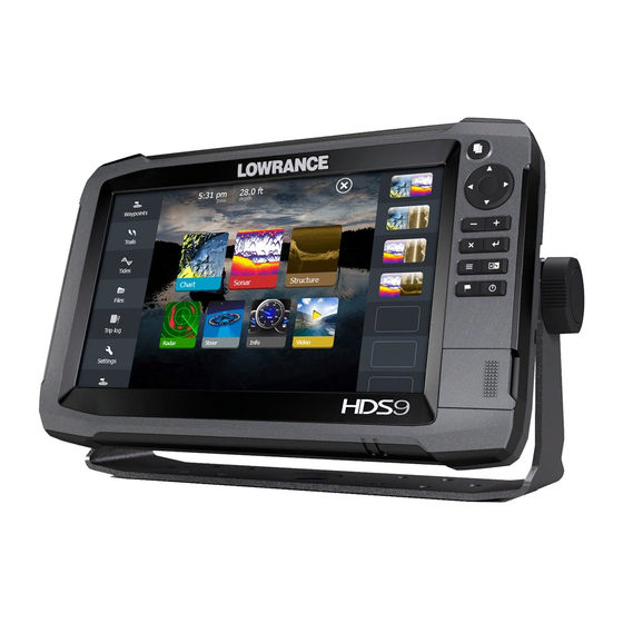
- Page 1 HDS Gen3 Installation Manual ENGLISH lowrance.com...
- Page 3 The warranty card is supplied as a separate document. In case of any queries, refer to the brand web site of your display or system: www.lowrance.com Declarations and conformance This equipment is intended for use in international waters as well as inland waters and coastal sea areas administered by...
-
Page 4: Industry Canada
Compliance Statements Lowrance HDS-7, HDS-9, and HDS-12 Gen3: • complies with CE under R&TTE directive 1999/5/ • complies with the requirements of level 2 devices of the Radio-communications (Electromagnetic Compatibility) standard 2008 • This device complies with Part 15 of the FCC Rules. - Page 5 reasonable protection against harmful interference in a residential installation. This equipment generates, uses and can radiate radio frequency energy and, if not installed and used in accordance with the instructions, may cause harmful interference to radio communications. However, there is no guarantee that the interference will not occur in a particular installation.
- Page 6 Countries of intended use in the EU: AT - Austria BE - Belgium BG - Bulgaria CY - Cyprus CZ - Czech Republic DK - Denmark EE - Estonia FI - Finland FR - France DE - Germany GR - Greece HU - Hungary IS - Iceland IE - Ireland IT - Italy...
-
Page 7: About This Manual
About this manual This manual is a reference guide for installing the Lowrance HDS-7, HDS-9, and HDS-12 Gen3 displays. The manual does not cover basic background information about how equipment such as radars, sonar, and AIS work. Important text that requires special attention from the reader is emphasized as follows: ... -
Page 8: Table Of Contents
Contents HDS Gen3 overview Front - controls Rear - connectors SD card slot Check the contents Display Installation Mounting location Bracket mounting Flush mounting Mounting the transducer Research Select a transducer location Attaching the transducer Adjusting the transducer Wiring Guidelines Power connection Transducer connection Ethernet device connection... - Page 9 Autopilot setup Fuel setup CZone setup NMEA 0183 setup Ethernet setup Wifi setup Video In confi guration Mercury® Software updates and data backup Dimensional drawings HDS 7 Gen3 HDS 9 Gen3 HDS 12 Gen3 Accessories NMEA 2000 Ethernet cables Display accessories Sonar accessories Other accessories Supported data...
-
Page 10: Hds Gen3 Overview
HDS Gen3 overview All HDS-7, HDS-9, and HDS-12 Gen3 multifunction displays have built-in CHIRP/Broadband sonar, and StructureScan, capable of operating simultaneously. The ability to network over NMEA 2000 and Ethernet allows access to data as well as control of numerous optional devices that can provide sonar, radar, audio entertainment, weather and even digital switching. -
Page 11: Front - Controls
Front - controls Multi-touch touchscreen Pages Cursor (8-way) Zoom out / Zoom in (combined press = MOB) Exit (X) Enter Menu (short press = menu, long press = hide menu bar, double press = Settings menu) Active panel New waypoint (long press = fi nd dialogue) Power key (short press = system controls, long press = power off ) Card reader door... -
Page 12: Rear - Connectors
Rear - connectors HDS-9 / 12 HDS-7 2 2 3 2 1 4 5 3 NMEA 2000 - data input / output ETHERNET - high bandwidth data (radar, sonar, chart) POWER - 12V input & NMEA 0183. Optional video-in via adaptor SONAR - CHIRP and Broadband Sonar STRUCTURE - StructureScan HD sonar... -
Page 13: Sd Card Slot
MicroSD card slot Used for detailed chart data, software updates, transfer of user data and system backup. All size displays have two card reader slots. The card reader door is opened by sliding the door to the right (1) using your fi ngernail, then hinging forward (2) from the right hand side. -
Page 14: Check The Contents
Check the contents HDS Gen3 display Suncover Bracket Knobs Fasteners (4 x 6G x 1.5 panhead PH1) Power cable Fuse holder (ATC blade) Fuse (3 amp) Caps (3x for HDS7 4x for HDS9/12 - for ethernet, NMEA 2000, StructureScan) Documentation pack (Operator & Installation manual, Quick guide, warranty card) 83/200 kHz transducer (model dependant) StructureScan HD transducer (model dependant) -
Page 15: Display Installation
Be sure to leave a direct path for all of the cables. Lowrance displays are high-contrast, and are viewable in direct sunlight, but for best results install the display out of direct sunlight. -
Page 16: Bracket Mounting
Bracket mounting Place the bracket in the desired mounting location, and use a pencil or permanent marker to mark drilling locations. Note: ensure that the chosen location has enough height to accomodate the display fi tted in the bracket, and allows tilting of the display. -
Page 17: Flush Mounting
Flush mounting Check the template for scaling accuracy, using a tape measure or ruler against the ruler printed on the template. Cut away excess paper, and tape down the template. Check that it is correctly aligned to a vertical or horizontal 0 "... -
Page 18: Mounting The Transducer
Mounting the transducer Transducer location selection and installation are two of the most critical steps in sonar installation. To function properly the transducer must be in the water at all times, and in a location that has a smooth fl ow of water while the boat is moving. Research Before starting the installation of the transducer, it’s advised to check the following:... -
Page 19: Attaching The Transducer
Note: Boats with strakes or ribs on the hull can create large amounts of turbulence at higher speeds. A good transducer location on these types of boats is between the ribs closest to the engine. Note: If the transducer is not placed in a smooth fl ow of water, interference caused by bubbles and turbulence may show on- screen in the form of random lines or dots. -
Page 20: Adjusting The Transducer
Secure the cable to the hull at regular intervals using cable P clips or saddles and ensure that moving parts such as an outboard motor or boarding ladder can’t snag the cable. Adjusting the transducer If the sonar image shows interference lines on the screen when moving, which worsen with speed, it may be possible to eliminate these by adjusting the transducer’s angle. -
Page 21: Wiring
Wiring Guidelines Don’t do this Do this Don’t make sharp bends in the Do make drip and service loops cables Don’t run cables in a way that Do cable tie all cables to keep allows water to fl ow down into them secure the connectors Don’t route the data cables... -
Page 22: Power Connection
Power connection The plug of the supplied power cable has two discrete cables exiting from it. The thickest of the two cables provides the following: • power into the system (Red and Black wires) • remote turn-on for certain Navico expansion modules (Yellow wire) HDS display rear (HDS9/12 connector arrangement shown) Power cable 12 V positive wire (red) shown with fuse holder installed... - Page 23 HDS Displays (HDS7 connector arrangement shown) HDS power cable Broadband radar interface SonicHub 12 V DC negative (-) 12 V DC postive (+) Accessory wake up line Vessel’s 12 V DC supply | 21 Wiring | HDS Gen3 Installation Manual...
-
Page 24: Transducer Connection
Note: The HDS StructureScan port is designed for use with the LSS-2 transducer. Earlier LSS-1 transducers may however be connected through use of an adaptor cable - contact your Lowrance dealer for more information. SpotlightScan The SpotlightScan transducer uses both the ‘Sonar’ and ‘Structure’... -
Page 25: Ethernet Device Connection
Ethernet device connection Ethernet is used to connect high bandwidth devices such as radar, sonar, and other displays. The HDS-7 display has one ethernet port, whereas the HDS-9 and 12 displays have two. Navico ethernet cables have a locking collar, for maintaining a reliable, waterproof connection. -
Page 26: Nmea 2000 Device Connection
NMEA 2000 device connection All HDS Gen3 models are equiped with a NMEA 2000 connector, which allows the receiving and sharing of a multitude of data from various sources. Essential network information • A network consists of a linear ‘backbone’ from which ‘drop cables’ connect to NMEA 2000 compliant devices. - Page 27 12 V DC GPS antenna HDS Display Broadband radar interface SonicHub ‘Drop’ cables (should not exceed 6m (20’) each) Power cable Micro-C T-connectors Backbone Terminators (one male, one female) | 25 Wiring | HDS Gen3 Installation Manual...
-
Page 28: Nmea 0183 Device Connection
NMEA 0183 device connection The HDS Gen3 display has an NMEA 0183 serial port, providing both an input and an output. The port uses the NMEA 0183 (serial balanced) standard, and can be confi gured in the software for diff erent baud rates up to 38,400 baud. The NMEA 0183 cable shares the same plug as the power cable. -
Page 29: Video In
Talkers and Listeners Do not connect multiple devices outputing data (Talkers) on to the input (Rx) of the unit. The protocol is not intended for this type of connection, and data will be corrupted if more than one device transmits simultaneously. The output however may drive multiple receivers (Listeners). -
Page 30: Software Setup
Software setup The HDS Gen3 requires some initial confi guration before use, in order to get the most out of the product. The following sections focus on settings that typically will not require change once confi gured. User preference settings and operation are covered in the operator manual. - Page 31 Read and accept warning. Skip demo mode by selecting NO Select ‘Confi gure this Device’ to answer some questions that will determine a number of presets suited to typical use. Will set units of measure for values such as depth and distance. | 29 Software setup | HDS Gen3 Installation Manual...
-
Page 32: Time And Date
Set fi shing mode. One of two options below will be displayed, depending on selection. Sonar presets will be adjusted to best suit selection made. All presets can be adjusted at a later date via the sonar page menu, and under settings/sonar. -
Page 33: Source Selection
Source selection Data sources provide live data such as GPS position, heading, wind speed, and temperature. The data may originate from modules internal to the device (eg internal GPS on some products), or external modules connected via NMEA 2000 or NMEA 0183. Internal sources presented on NMEA 2000 as ‘virtual’... -
Page 34: Device List
Confi gure device Additional device options can be confi gured from both the Data source menu or from the Device list, see “Device list” on page 32 for further information. Scope The active data source under any given category, can be set to be Global or Local. - Page 35 All devices allow allocation of an instance number via the Confi gure option. Set unique instance numbers on any identical devices on the network to allow for HDS to distinguish between them. Some devices will have additional options on the confi gure page, such as selecting a device location, or reseting calibration applied.
-
Page 36: Diagnostics
Diagnostics The NMEA 2000 tab on the diagnostics page can provide information useful for identifying an issue with the network. Bus state: This simply indicates whether the bus is powered, but not necessarily connected to any data sources. However if bus shows as ‘off ’... -
Page 37: Sonar Setup
Sonar setup The Installation page allows confi guration of the internal sonar. Keel off set This is a value that can be entered on the Sonar Installation page to make depth readings relate to any point from the water surface, to the deepest point of the vessel. -
Page 38: Structurescan And Spotlightscan
Water speed averaging (sonar transducer) Averages water speed by measuring your speed at a selected interval of time. Water speed intervals range from one to thirty seconds, e.g. if you select fi ve seconds, your displayed water speed will be based on averaging over 5 seconds of sampling. Calibration range: 1-30 seconds. -
Page 39: Radar Setup
Radar setup Setup and use of the Broadband radar has been simplifi ed when compared to traditional pulse radars. There is no zero range (time delay), no warm up time, and no burn-in required. Radar status Displays scanner information, the availability and status of scanner features, and the status of radar peripherals. -
Page 40: Autopilot Setup
Sidelobe suppression (Broadband radar only) Note: This control should only be adjusted by experienced radar users. Target loss in harbour environments may occur if this control is not adjusted correctly. Occasionally, false target returns can occur adjacent to strong target returns such as large boats or container ports. -
Page 41: Fuel Setup
Fuel setup The fuel utility monitors the vessel’s fuel consumption. This information is totalled to indicate trip and seasonal fuel usage. Instantaneous fuel usage and boat speed data is used to calculate fuel economy for display on instrument pages and data overlays. To use the utility, a Navico Fuel Flow sensor or a NMEA 2000 engine adaptor cable/gateway with Navico Fuel Data Storage device must be fi tted to the vessel. - Page 42 ‘Unconfi gure’ is for defaulting the device clearing all user settings, and ‘Reset Fuel Flow’ will restore only the ‘Fuel K-Value’ setting, if set in ‘Calibrate’ . Only Navico devices can be reset. Calibrate While default calibration is usually accurate enough, it is possible to apply further calibration to accurately match measured fl ow with actual fuel fl ow.
-
Page 43: Czone Setup
The functionality of the CZone system is determined by the CZone Confi g File (.zcf ), which is stored on all CZone modules and supported Lowrance displays, such as the HDS Gen3. The fi le is created using the CZone Confi guration Tool, a specialised PC application available from BEP Marine Ltd, and associated CZone distributors. - Page 44 Once CZone is enabled, a CZone icon appears in the Settings menu. Assigning the dipswitch setting Every Lowrance product capable of controlling and viewing CZone devices must be assigned a virtual dipswitch setting. This setting is unique for each device. Typically, it is set after the confi g fi le already exists on the CZone system, but it may also be set in advance.
-
Page 45: Nmea 0183 Setup
Upgrading module fi rmware The fi les page also allows the loading of CZone module fi rmware updates. For further information refer to “NMEA 2000 and Ethernet device upgrades” on page 52 NMEA 0183 setup The NMEA 0183 port must be set to suit the speed of connected devices, and can be confi gured to output only the sentences required by listening devices. -
Page 46: Ethernet Setup
Commonly used sentences are enabled by default. NMEA 0183 over Ethernet The NMEA 0183 data stream is also output over ethernet, which is made available to tablet devices and PCs, using the WIFI-1 wireless adaptor. The Ethernet dialogue provides IP and port data typically required for confi guring the application on the third party device. - Page 47 The upper table on the diagnotics page gives an account of the various automatically synchronised databases that ensure all Lowrance displays are using the same user settings and data. Each unit stores the database locally, so that all information is available if the device is run in standalone.
-
Page 48: Wifi Setup
Module network light The network LED on modules such as NEP-2, SonarHub, WIFI-1, and RI10, can be useful for determining if the network is communicating. No light indicates no connection. A rapidly blinking green LED means the network module is communicating with another device. Wifi setup The HDS Gen3 can be veiwed and controlled via an Android or Apple tablet, using the internal wireless AP (or a WIFI-1 module) -
Page 49: Remote Controllers
Note: The HDS Gen3 internal wireless module only supports GoFree connection to it’s own display. Other displays connected via ethernet are not visible. Note: If it’s required to show all displays available for control/viewing via one wireless connection, use the external WIFI-1 module. Remote controllers When a wifi device is connected, it should appear in the Remote controllers list. - Page 50 Mode (WIFI-1 only) When more than one WIFI-1 device is connected (i.e. on large installations), only one may operate as ‘Primary’ . Primary mode determines that the device is acting as DHCP server - only one DHCP server may exist on a network at a time. To set a device as secondary, the HDS Gen3 must initially be connected to only one WIFI-1 module, which should be set to ‘secondary’...
-
Page 51: Video In Confi Guration
Software updates and data backup From time to time Lowrance releases software updates to its existing products. Updates are created for a variety of reasons; to add or improve features, to add support for new external devices, or to fi x software bugs. - Page 52 Updates can be found on the Lowrance website: http://www. Lowrance.com The HDS Gen3 may be used to apply software updates to itself, and to supported NMEA 2000 and ethernet devices, with fi les read off a microSD card. Before initiating an update to the HDS Gen3 itself, be sure to back up any potentially valuable user data.
- Page 53 NSS evo2, NSS, NSO, NSE, Zeus, Zeus Touch, HDS Gen2, HDS Gen2 Touch, HDS Gen3). • User data fi le version 3 (with depth): Use with legacy Lowrance GPS chartplotters • User data fi le version 2 (no depth): Use with legacy Lowrance GPS chartplotters •...
- Page 54 Remote updating is similar to updating a local display; select the fi le on the microSD card and select ‘Upgrade’ option, followed by ‘Remote Upgrade’ . Follow the onscreen options. NMEA 2000 and Ethernet device upgrades The update fi le must be loaded to the root directory of an microSD card.
-
Page 55: Dimensional Drawings
Dimensional drawings HDS 7 Gen3 83.7mm (3.3”) 215.4mm (8.48”) 32.3mm (1.27”) 238.4mm (9.39”) 69.2mm (2.72”) 96.5mm (3.8”) HDS 9 Gen3 86.1mm (3.39”) 32.2mm (1.27”) 265.0mm (10.43”) 60.55mm (2.38”) 286.7mm (11.29”) 84.0mm (3.31”) HDS 12 Gen3 57.9mm (2.28”) 32.6mm (1.28”) 328.1mm (12.92”) 62mm (2.44”) 351mm (13.82”) 85.1mm (3.35”) -
Page 56: Accessories
Accessories Refer to the website for the full range of available accessories: www.lowrance.com NMEA 2000 Part number Description 000-0124-69 NMEA 2000 STARTER KIT 000-0119-88 N2KEXT-2RD 2’ (0.61M) EXTENSION CABLE 000-0127-53 N2KEXT-6RD 6’ (1.82M) EXTENSION CABLE 000-0119-86 N2KEXT-15RD 15’ (4.55M) EXTENSION CABLE 000-0119-83 N2KEXT-25RD 25’... -
Page 57: Sonar Accessories
000-0106-74 TROLLING MOTOR TRANSDUCER, 83/200 000-0106-73 IN-HULL SHOOT-THRU, DEPTH ONLY 000-0106-89 IN-HULL, SHOOT-THRU, DEPTH + REMOTE TEMP. For additional transducer options, visit www.lowrance.com Other accessories Part Number Description 000-11076-001 WM-3 SIRIUS® WEATHER MODULE 000-11068-001 WIFI-1 WIRELESS NETWORK MODULE 000-10418-001 3G BROADBAND RADAR... -
Page 58: Supported Data
Supported data NMEA 2000 compliant PGN List NMEA 2000 PGN (receive) 59392 ISO Acknowledgement 59904 ISO Request 60928 ISO Address Claim 61184 Parameter Request/Command 65285 Temperature with Instance 65289 Trim Tab Insect Confi guration 65291 Backlight Control 65292 Clear Fluid Level Warnings 65293 LGC-2000 Confi guration 65323... - Page 59 127509 Inverter Status 128259 Speed, Water referenced 128267 Water Depth 128275 DistanceLog 129025 Position, Rapid Update 129026 COG & SOG, Rapid Update 129029 GNSS Position Data 129033 Time & Date 129038 AIS Class A Position Report 129039 AIS Class B Position Report 129040 AIS Class B Extended Position Report 129283...
- Page 60 130820 Reprogram Status 130831 Suzuki Engine and Storage Device Confi g 130832 Fuel Used - High Reolution 130834 Engine and Tank Confi guration 130835 SetEngineAndTankConfi guration 130838 Fluid Level Warning 130839 Pressure Insect Confi guration 130843 Sonar Status, Frequency and DSP Voltage 58 | Supported data | HDS Gen3 Installation Manual...
- Page 61 NMEA 2000 PGN (transmit) 61184 Parameter Request/Command 65287 Confi gure Temperature Insects 65289 Trim Tab Insect Calibration 65290 Paddle Wheel Speed Confi guration 65291 Backlight Control 65292 Clear Fluid Level Warnings 65293 LGC-2000 Confi guration 126208 ISO Command Group Function 126992 System Time 126996...
- Page 62 130819 Request Reprogram 130828 Set Serial Number 130831 Suzuki Engine and Storage Device Confi g 130835 SetEngineAndTankConfi guration 130836 Fluid Level Insect Confi guration 130837 Fuel Flow Turbine Confi guration 130839 Pressure Insect Confi guration 130845 Weather and Fish Prediction and Barometric Pressure History 130850 Evinrude Engine Warnings...
-
Page 63: Nmea 0183 Supported Sentences
NMEA 0183 supported sentences TX / RX Receive Transmit Navigation Receive Transmit AAM BWC BWR RMC RMB XTE XDR Sonar Receive MTW VLW VHW Transmit MTW VLW VHW Compass Receive Transmit HDG Wind Receive MWV MWD Transmit MWV MWD AIS / DSC Receive MARPA Transmit... -
Page 64: Specifi Cations
Specifi cations Refer to website for updates to specifi cations: www.lowrance.com Multi Function Display HDS-7 HDS-9 HDS-12 Display Display resolution 800x480 1280x800 Display type 7 inch WVGA color TFT LCD 9 inch WVGA color TFT LCD 12.1 inch WXGA TFT LCD Display brightness >1200 nits... - Page 66 0980...
Need help?
Do you have a question about the HDS-7 HDS Gen3 and is the answer not in the manual?
Questions and answers