Advertisement
Table of Contents
- 1 Assembly
- 2 Table of Contents
- 3 Identification of the Main Components
- 4 Symbols
- 5 Safety Requirements
- 6 Machine Assembly
- 7 Preparing to Work
- 8 How to Start - Use - Stop the Engine
- 9 Using the Machine
- 10 Maintenance and Storage
- 11 Technical Specifications
- 12 Troubleshooting
- 13 Technical Data
- 14 Accessories
- Download this manual
Advertisement
Table of Contents

Summary of Contents for Mac allister MBCP254 DUPLEX
- Page 1 Brushcutter MBCP254 DUPLEX OPERATOR’S MANUAL WARNING: read thoroughly the instruction booklet before using this machine...
- Page 2 ENGLISH - Original Instructions ..............
- Page 4 STOP START STOP START CHOKE...
- Page 5 0,5 mm Ø 2,4 mm 30° 30° 120 mm (4,75 in.)
-
Page 7: Table Of Contents
INTRODUCTION Dear Customer, thank you for choosing one of our products. We hope that you will be completely satisfied with this machine and that it fully meets your expectations. This manual has been compiled in order to provide you with all the information you need to get acquainted with the machine and use it safely and efficiently. -
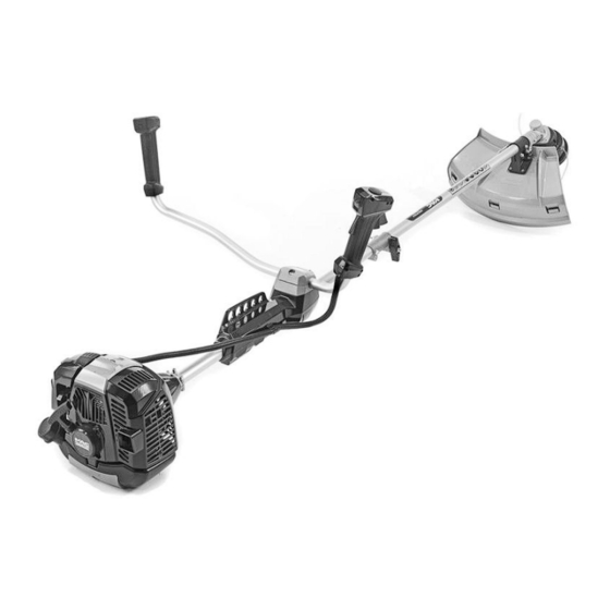
Page 8: Identification Of The Main Components
IDENTIFICATION OF MAIN COMPONENTS 1. IDENTIFICATION OF MAIN COMPONENTS MAIN COMPONENTS 1. Power unit 2. Drive tube 3. Cutting device a. Blade with 3 points “MONO” b. Cutting line head 4. Cutting device guard 5. Front handgrip 6. Guard 7. Handlebar 8. -
Page 9: Symbols
SYMBOLS 2. SYMBOLS 1) Warning! Danger. The failure to use this machi- 6) Maximum cutting device speed. Only use sui- ne correctly can be hazardous for oneself and oth- table cutting devices. ers. 7) Do not use the circular saw blade. Danger: 2) Read the instruction manual before using the Using the circular saw blade with machines machine. -
Page 10: Safety Requirements
SAFETY REQUIREMENTS 3. SAFETY REQUIREMENTS A) TRAINING – keep the fuel in containers which have been spe- cifically manufactured and homologated for such 1) Read the instructions carefully. Become ac- use; quainted with the controls and the proper use of the –... - Page 11 SAFETY REQUIREMENTS 3) Take on a firm and well-balanced position: 4) To reduce fire hazards, keep the engine, ex- – where possible, avoid working on wet, slippery haust silencer and fuel storage area free from saw- ground or in any case on uneven or steep ground dust, branches, leaves, or excessive grease;...
-
Page 12: Machine Assembly
MACHINE ASSEMBLY 4. MACHINE ASSEMBLY both directions. The pin (5) is in place when it is IMPORTANT The machine is supplied with completely lodged in the hole. some of the components disassembled and the – Lastly, tighten the knob (7) securely. fuel tank empty. -
Page 13: Preparing To Work
MACHINE ASSEMBLY / PREPARING TO WORK • Cutting line head (Fig. 7) NOTE The fastening nut (5) has a left-hand thread and so must be unscrewed in a clockwise direction and screwed up anticlockwise. NOTE The cutting line head has a left-hand thread and so must be unscrewed in a clockwise direction and screwed up anticlockwise. -
Page 14: How To Start - Use - Stop The Engine
PREPARING TO WORK / HOW TO START - USE - STOP THE ENGINE – Keep the petrol and fuel mixture in homolog- IMPORTANT Periodically clean the petrol ated fuel containers, in safe place, away and fuel mixture containers to remove any eventual from any flames or heat sources. - Page 15 HOW TO START - USE - STOP THE ENGINE 3. Press the primer device button (6) 3 or 4 times USE OF THE ENGINE (Fig. 8) to prime the carburettor. 4. Hold the machine firmly on the ground with one Cutting device speed is regulated by the throttle hand on the power unit, in order not to lose trigger (2), located on the rear handgrip (4) or the...
-
Page 16: Using The Machine
USING THE MACHINE 7. USING THE MACHINE If the machine has more than one coupling hole, use To respect people and the environment: the most favourable point for keeping the machine balanced when working. – Try not to cause any disturbance. Always use webbing suited to the weight of the ma- –... - Page 17 USING THE MACHINE • Choosing the cutting device WARNING! Do not work in this way if there is the possibility of causing objects to be Choose the most suitable cutting device for the job to thrown, which could harm people and animals be done, according to these general indications: and cause damage.
-
Page 18: Maintenance And Storage
MAINTENANCE AND STORAGE 8. MAINTENANCE AND STORAGE Correct maintenance is essential to maintain the Clean the filter as follows: original efficiency and safety of the machine over time. – Press the button (1), turn the cover (2) over and remove the filter element (3). –... - Page 19 MAINTENANCE AND STORAGE SHARPENING THE 3 POINT BLADE STORAGE (Fig. 20) After every work stint, clean the machine thor- oughly to remove all dust and debris, and repair or WARNING! replace any faulty parts. Use protective gloves. If sharpening is done without removing the blade, disconnect the spark plug cap.
-
Page 20: Troubleshooting
TROUBLESHOOTING / TECHNICAL SPECIFICATIONS 9. TROUBLESHOOTING PROBLEM LIKELY CAUSE SOLUTION 1) The engine will – Incorrect starting procedure – Follow the instructions not start or will not (see chapter 6) keep running – Dirty spark plug or incorrect – Check the spark plug distance between the electrodes (see chapter 8) –... - Page 21 TECHNICAL SPECIFICATIONS Model Maximum noise and vibration levels MBCP254 Operator ear noise pressure level (EN ISO 22868) with line cutter head dB(A) Measurement uncertainty (2006/42/EC - EN 27574) dB(A) with 3-point blade dB(A) Measurement uncertainty (2006/42/EC - EN 27574) dB(A) Measured sound power level (EN ISO 22868) with line cutter head dB(A)
-
Page 22: Accessories
ACCESSORIES 11. ACCESSORIES The table contains a list of all available acces- latter assumes responsibility for damages of sories, indicating those which may be used on any kind due to such actions. When in doubt or each machine, marked with the symbol “ ”. - Page 24 B&Q plc. Chandlers Ford, Hants, SO53 3LE, United Kingdom...
Need help?
Do you have a question about the MBCP254 DUPLEX and is the answer not in the manual?
Questions and answers