Table of Contents
Advertisement
M42411C
Instructions for Installation/Set-up, Operation, Servicing, & Storage
Portable, Outdoor Use-Only, Gasoline Generator
Can be used to power individual appliances plugged directly into the generator's outlets, or as a back-up
connection to a building's power supply (via a professionally installed UL-approved transfer switch).
READ and UNDERSTAND this manual completely before using the generator! Failure to properly set up,
operate, and maintain this generator could result in serious injury or death from carbon monoxide poisoning,
electric shock, fire/explosion, or burns. Generator has been shipped WITHOUT engine oil, Check the oil level
using the dipstick and add oil as needed. In particular, be aware of the following hazards:
Generators give off carbon monoxide, a poisonous gas that can kill you. You CANNOT smell it, see it, or taste it.
ONLY run generator OUTDOORS and AWAY from building air intakes. NEVER run generator inside any enclosed or
semi-enclosed spaces, including homes, basements, garages, sheds, boxes, RVs, boats or pick-up truck beds. These
spaces can trap poisonous gases, EVEN if you run a fan or open windows.
Install carbon monoxide alarms inside nearby structures/buildings (battery-operated, or plug-in with battery backup).
High voltage electricity from generator can kill. DO NOT operate in wet locations. Be sure generator is properly
grounded. Use only UL-listed, outdoor-rated grounded extension cords of proper size.
NEVER plug the generator directly into a wall outlet. ANY connection to a building's electrical system MUST
ISOLATE THE GENERATOR FROM UTILITY POWER via a UL-approved transfer switch installed by a licensed
electrician. Otherwise, back feed from the generator into the power grid could kill utility workers.
DO NOT overload generator (per rated capacity), and OPERATE ONLY in an area with adequate cooling ventilation so
engine does not overheat. Exhaust can be extremely hot. Keep muffler at least 7 feet from all combustible objects.
All fuels are flammable. Never fuel a running or hot engine. Never pump fuel directly into generator at gas station – use
approved container to transfer fuel. Ensure there are no fuel leaks, and keep sources of sparks and flames away.
ALWAYS keep a fire extinguisher rated "ABC" nearby.
CHOOSE THE RIGHT GENERATOR FOR YOUR NEEDS. See the "Power load Planning & Management" section
of this manual to determine your power load requirements and then compare to the generator's rated capacity.
INSPECT COMPONENTS: Closely inspect to make sure no components are missing or damaged. See the "Unpacking
& Delivery Inspection" section for instructions on whom to contact to report missing or damaged parts.
ARRANGE FOR PROFESSIONAL INSTALLATION of a transfer switch if you will be connecting the generator to
your building's electrical system. See the "Installation/Initial Set-Up" section for more information about this
requirement.
Any Questions, Comments, Problems, or Parts Orders
Owner's Manual
WARNING
Electric shock / Electrocution
Fire / Explosion
Call Powerhorse Product Support 1-866-443-2576
Item Number: 42411
Serial Number: _____________
CO Poisoning
STOP!
Advertisement
Table of Contents

Related Manuals for Powerhorse M42411C


Summary of Contents for Powerhorse M42411C
- Page 1 ARRANGE FOR PROFESSIONAL INSTALLATION of a transfer switch if you will be connecting the generator to your building’s electrical system. See the “Installation/Initial Set-Up” section for more information about this requirement. Any Questions, Comments, Problems, or Parts Orders Call Powerhorse Product Support 1-866-443-2576...
-
Page 2: Hazard Signal Word Definitions
Hazard Signal Word Definitions... -
Page 3: Table Of Contents
Table of Contents Hazard Signal Word Definitions ....................2 About Your Generator ........................4 Specifications ........................... 6 Safety Label Locations ........................7 Machine Component Identification ....................9 Power Load Planning & Management ..................11 Installation / Initial Set-Up: 1. Unpacking & Delivery Inspection ..................14 2. -
Page 4: About Your Generator
For detailed engine operation and maintenance information, always refer to the engine Owner’s Manual furnished with the generator. Powerhorse is constantly improving its products. The specifications outlined herein are subject to change without prior notice or obligation. The purchaser and/or user shall assume liability for any... -
Page 5: Warranty Registration
About Your Generator Before using, the user shall determine the suitability of this product for its intended use and assumes liability therein. Contact Powerhorse Product Support at 1-866-443-2576 for any questions about the appropriate use of this generator. Warranty Registration Please fill in the warranty registration information in the back of this manual and have it on hand when you call in on a warranty claim or replacement parts. -
Page 6: Specifications
0.42 US quarts (0.35L) Noise Level 52 dBA ~ 61 dBA @ 7 meters Starting Method Recoil Dimensions Length 19.64” Width 11.22” Height 17.91” Dry Weight 46 lbs. Any Questions, Comments, Problems, or Parts Orders Call Powerhorse Product Support 1-866-443-2576... -
Page 7: Safety Label Locations
Always make sure safety labels are in place and in good condition. If a safety label is missing or not legible, order new labels or unsafe operation could result. To order replacement safety labels, call Powerhorse Product Support at 1-866-443-2576. - Page 8 Safety Label Locations...
-
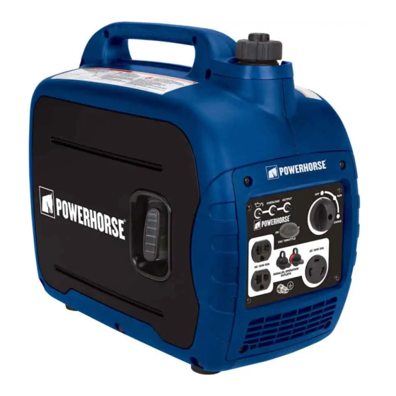
Page 9: Machine Component Identification
Machine Component Identification Ref. Description Ref. Description Carrying Handle Oil Fill Cover with Screw Recoil Starter Spark Plug Maintenance Cover Control Panel Muffler Fuel Tank Cap Hot Air Discharge Fuel Tank Cap Air Vent Knob Cool Air Intake Ref. Description Ref. - Page 10 Electrical device able to accept AC 120V 30A locking plugs Receptacles (NEMA L5-30R) (NEMA L5-30P) Reference 14 – Parallel This is the terminal for connecting two Powerhorse Inverter Generators using special cables. Operation Outlets Reference 15 – Engine This switch has the following positions: OFF/RUN/CHOKE control OFF - Stops the engine and closes the fuel valve.
-
Page 11: Power Load Planning & Management
Power Load Planning & Management WARNING NEVER exceed the rated wattage capacity of your generator. OVERLOADING may cause SERIOUS DAMAGE to the generator and attached electrical devices, and may result in fire. Your generator MUST BE SIZED PROPERLY to provide both the running and starting (surge) wattage of the devices you will be powering. - Page 12 Power Load Planning & Management (cont’d) Running Watts Starting Watts Device (Continuous) (Surge) Clothes Dryer (gas) 1200 Clothes Washer 1150 2300 Coffee Maker 1750 Deep Freezer 1000 Desktop Computer w/ 17" monitor Dishwasher (Hot Dry) 1500 1500 Drill: 1/2in., 5.4 Amps Drill: 3/8in., 4 Amps DVD/CD Player Electric Fence: 25 Miles...
- Page 13 Power Load Planning & Management (cont’d) To calculate the running and starting wattage requirements for the devices you will be powering, follow these steps: 1. Make a list of all electrical devices you will be powering at the same time with the generator. 2.
-
Page 14: Installation / Initial Set-Up
Installation / Initial Set-Up There are a number of important steps required to set up your generator for initial use. These steps are: Steps for Installation / Initial Set-Up 1. Unpacking & delivery inspection. 2. Planning the power load to stay within the generator’s rated capacity. -
Page 15: Set-Up Either As A Building Back-Up Or Portable Power Source
Installation / Initial Set-Up 3. Set-up either as a BUILDING BACK-UP or PORTABLE Power Source This generator is designed to provide up to its rated amount of electrical power. It can supply electricity in two ways: 1. As a back-up, standby power source for a building. For this application, you must arrange for a licensed electrician to connect the generator to your building’s electrical system via the installation of an UL-approved transfer switch. - Page 16 Installation / Initial Set-Up normal line voltage. An unsuspecting utility line worker working on what he thinks is a deactivated line could be electrocuted. If your generator is connected (running or not) when utility power is restored, your generator will be destroyed. It could also explode or cause fire.
- Page 17 Installation / Initial Set-Up WARNING: Use of under sized extension cords can cause electric shock, fire, or damage to connected devices. 3. All extension and appliance cords must be in good condition and not worn, bare, frayed, or otherwise damaged. WARNING: Use of damaged electric cords can cause electric shock or fire.
-
Page 18: Selecting A Suitable Site
Installation / Initial Set-Up 4. Select a Suitable Site Before using the generator, you must select a suitable OUTDOOR location for installation and operation. This location should meet all of the criteria listed below. WARNING: You must choose a suitable site for operating your generator to avoid equipment damage and/or injury and possible death from carbon monoxide poisoning, electric shock, or fire. - Page 19 Installation / Initial Set-Up Adequate cooling The generator needs adequate, unobstructed flow of air to allow for ventilation proper cooling of engine and generator head. WARNING: Heat build-up from inadequate ventilation can result in fire, posing a serious risk to nearby persons and structures. ...
-
Page 20: Grounding The Generator
Installation / Initial Set-Up 5. Grounding the Generator Always ensure the generator is properly grounded to prevent electrical shock. You must always ground the generator by the following method when using the generator as a portable electrical source: 1) Drive a 3/4” or 1” copper pipe or rod into the ground close to the generator. The pipe/rod must penetrate moist earth –... -
Page 21: Operation
Operation Once you have set up your generator for use, it is time to start your generator. The following are the procedures necessary for safe, successful operation of your generator. Operation Procedures 1. General Safety Rules for Operation 2. Preparing for Operation 3. - Page 22 Operation Malfunction during operation. Immediately turn off the generator if any of the following conditions arise during operation: o Excessive change in engine speed, slow or fast o Overheating in load connecting devices o Sparking or arcs from generator o Loss of electrical output o Receptacle damage o Engine misfire...
- Page 23 Operation Static electricity and filling the gasoline tank: Static electricity can initiate from ungrounded gasoline tanks or containers, from flowing gasoline, and from persons carrying a static electric charge Static electricity can explosively ignite gasoline vapors that are present during the fueling process, resulting in serious burns to nearby persons.
-
Page 24: Preparing For Operation
Operation 2. Preparing for Operation Position Position generator in accordance with the instructions given in “Installation & Initial Set-up, Step 4: Select a Suitable Site” generator of this manual. Operate outside only, on dry, level ground with adequate clearance and ventilation. - Page 25 Operation 4) Fill with the recommended amount and type of engine oil, then install and tighten the oil filler cap. Max oil level Min oil level 5) Install the oil fill cover 2 and tighten the screw 1. (See specification section for oil type and capacity.) WARNING: Burn hazard Never open oil port while engine is running.
- Page 26 Operation gas vapor collection inside enclosures static electric sparks sparks from electric wiring, batteries, or running engines sources of heat (such as a hot engine or exhaust) open flames, including pilot lights 1) Before starting, review the following general safety precautions for fueling: a) Never pump gasoline directly into the generator’s gas tank at a gas station –...
- Page 27 Operation WARNING: Static electric spark hazard A static electric spark can explosively ignite gasoline vapor, resulting in a flash fire that could cause serious injury or death. To avoid static electric sparking while filling the gasoline tank, the following steps must be followed to minimize and safely dissipate static electric charge build-up before and during the fueling process: ...
- Page 28 Operation loose connections, loose or missing fuel hose clamps, a damaged gasoline tank, or a defective gasoline shut-off valve. Personal 1) Hearing can be damaged from prolonged, close-range exposure to the type of noise produced by this generator. The use of ear plugs or other hearing Protection protection device is recommended for persons working within 15-20 feet of the running generator for an extended period of time.
-
Page 29: Starting The Generator
Operation 3. Starting the Generator After you have completed the pre-start checklist procedures, you are ready to start the generator. To start the engine: 1) Turn the ESC throttle switch 1 to “OFF”. 2) Turn the fuel cap air vent knob to “ON” 2. 3) Turn the Engine OFF/RUN/CHOKE control 3 to A. - Page 30 Operation 4) Pull slowly on the recoil starter until it is engaged, then pull it briskly. NOTE: Grasp the carrying handle firmly to prevent the generator from falling over when pulling the recoil starter. 5) After a cold engine is started, allow time to warm up so when the knob is turned to the RUN position the generator will stay running.
-
Page 31: Checking Generator Output
Operation 4. Checking Generator Output Although the speed of the engine was carefully adjusted at the factory so that the generator produces the proper voltage and frequency, output voltage should be checked periodically to ensure the generator is working properly before connecting loads to the generator. Output voltage should be checked with a portable voltage meter: 1. -
Page 32: Connecting Loads
Operation 5. Connecting Loads You will want to be careful when connecting loads so as not to overload the generator, especially if you are powering devices with motors that require a higher starting power load. Instructions are provided below for connecting loads when you are using the generator: o As a portable power source o Connected to a building as a back-up power source WARNING:... -
Page 33: Ac Parallel Operation
Note: Most motorized appliances require more than their electrical rating for startup. When an electrical motor is started, the overload indicator (red) may come on. This is normal if the overload indicator (red) goes off within 4 seconds. If the overload indicator (red) stays on, contact Powerhorse Product Support @ 1-866-443-2576. - Page 34 Operation Follow the steps provided below for parallel operation. Connect Parallel 1. Connect the red parallel operation cable to the parallel operation outlets designated with the red o-ring on each of the generators. Cables 2. Connect the black parallel operation cable to the remaining parallel operation outlets on each of the generators.
-
Page 35: Storage & Exercise
Operation Storage & Exercise When you are finished using the generator, you must: o Disconnect all loads o Allow generator to completely cool down o Store the generator properly o Plan on exercising the engine regularly unless the generator is prepared for long-term storage. Detailed instructions are provided below. - Page 36 Operation Add fuel stabilizer: Prepare engine for 1. Ensure gasoline tank is full. 1 to 2 month storage 2. Add fuel stabilizer to fuel tank. 3. Run engine at least 10 minutes after adding stabilizer to allow it to enter the fuel system.
-
Page 37: Maintenance & Repair
Repair. Major service, including the installation or replacement of parts, should be performed only by a qualified electrical service technician. Obtain factory approved parts from Powerhorse Product Support at 1-866-443-2576. Replacement parts. If a part needs replacement, only use factory approved repair parts. - Page 38 Maintenance & Repair (cont’d) c) Remove the oil filler cap 3. d) Place an oil pan under the engine. Tilt the generator to drain the oil completely. e) Place generator on a level surface. f) Fill with the recommend amount and type of engine oil, then install and tighten the oil filler cap (See Specification section for oil type and capacity).
- Page 39 Maintenance & Repair (cont’d) Air filter check/replacement a) Place the generator on a level surface and warm up for several minutes. b) Remove the screws 1, and then remove the side cover 2. c) Remove the air filter screw 3 and then pull off air filter case cover 4.
- Page 40 Maintenance & Repair (cont’d) Spark plug cleaning and replacement a) Remove the access cover 1 and spark plug cap 2. Insert the spark plug wrench through the access cover opening.
- Page 41 Maintenance & Repair (cont’d) b) Slide the handlebar 3 through the hole in the spark plug wrench 4 and turn it counter clockwise to remove the spark plug. c) Check for discoloration and remove any carbon build up. The porcelain insulator around the center electrode of the spark plug should be a medium-to-light tan color.
- Page 42 Maintenance & Repair (cont’d) Fuel tank filter check/replacement a) Remove the fuel tank cap and filter. b) Clean the filter with gasoline. c) Wipe the filter and install it. d) Install the fuel tank cap.
- Page 43 Maintenance & Repair (cont’d) Fuel filter check/replacement a) Remove the screws 1 and the side cover 2. b) Hold and move up the clamp 4, then take off the hose 5 from the bottom of the tank 3. c) Remove the fuel filter 6. d) Clean the filter with gasoline.
- Page 44 Maintenance & Repair (cont’d) Draining the Carburetor a) Remove the side cover and screws. b) Loosen the carburetor drain screw. c) Drain fuel into suitable container. d) Tighten the carburetor drain screw. Carburetor Drain screw e) Install side cover 2 and tighten the screws 1. Check receptacles Check receptacles before each use to make sure they are not cracked or broken.
- Page 45 Maintenance & Repair (cont’d) Inspect fuel system / Inspect the fuel system and check for leaks on a regular basis. check for leaks 1) Inspect the entire fuel system. Look for: signs of leaks or deterioration, chafed or spongy fuel hose, loose connections, loose or missing fuel hose clamps, damaged gasoline tank, or defective gasoline shut-off valve.
- Page 46 If a part needs replacement, only use parts that meet the manufacturer’s specifications. Replace- ment parts that do not meet specifications may result in a safety hazard or poor operation of the generator. Contact Powerhorse Product Support at 1-866-443-2576 for any questions, problems, or parts orders.
-
Page 47: Troubleshooting
Troubleshooting Problem Possible Causes Possible Remedies Engine will not a) Low oil level. a) Fill crankcase to proper oil level. start. b) Fouled spark plug. b) Clean or replace spark plug. c) Out of fuel. c) Fill fuel tank. d) Switch in OFF position. d) Place switch in Run or Choke position. -
Page 48: Summary Of Important Safety Information For Operation
Summary of Important Safety Information for Operation This section provides a summary of the various safety procedures and measures that have been presented throughout the manual. Keep this summary handy and refer to it to refresh your memory about how to safely use your generator. WARNING Carefully read and make sure you understand the following safety information before using the generator. - Page 49 Summary of Important Safety Information for Operation (cont’d) Installation / Initial Set-up Safety Dry, level surface. Situate generator on a dry, firm, level surface. Ensure generator sits level and will not slide or shift during operation. Block wheels if applicable. ...
- Page 50 Summary of Important Safety Information for Operation (cont’d) Use approved container. Never pump fuel directly into engine at gas station. Static charge can build and ignite fuel. Use an UL approved fuel container to transfer gas to the engine. ...
- Page 51 Summary of Important Safety Information for Operation (cont’d) Refueling. DO NOT refuel the engine until it has cooled at least two minutes. Malfunction during operation. Immediately turn off the generator if any of the following conditions arise during operation: Excessive change in engine speed, slow or fast Overheating in load connecting devices Sparking or arcs from generator...
-
Page 52: Generator Exploded View
Generator Exploded View Rev – C Ref # Part # Description Ref # Part # Description Control Panel assembly Gasket gland Compression spring Control Panel w/decal Kit # 17 Washer Kit # 14, 15 Screw M5x12 & 18 Pin clip LED indicator light (2 red &... - Page 53 Generator Exploded View Rev – C...
-
Page 54: Generator Kit Exploded View
Generator Exploded View Rev – C Kit # 1 – Part # 791726 Cylinder Head Kit Part Ref # Part # Description PIN,DOWEL ∅8X10 GASKET, CYLINDER CYLINDER HEAD ASSY BOLT ,STUD ,EXHAUST BOLT ,STUD ,INLET BOLT, FLANGE M6X50 790968 SPARK PLUG E6TC PACKING , HEAD COVER COVER COMP., HEAD 790978... - Page 55 Generator Exploded View Rev – C Kit # 3 – Part # 790952 Crank Case Cover Kit Ref # Part # Description 790974 BOLT, FLANGE M6X20 OIL SEAL COVER , CRANKCASE 790975 CAP/DIPSTICK ASSY BALL BEARING 6204 790976 OIL LEVEL SWITCH 790977 BOLT, FLANGE M6X12 PLATE...
- Page 56 Generator Exploded View Rev – C Kit # 5 – Part # 790954 Camshaft Kit Ref # Part # Description CAMSHAFT ASSY. LIFTER, VALVE PUSH ROD VALVE KIT SEAL,GUIDE SPRING,VALVE RETAINER,VALVE SPRING VALVE LOCKER ROCKER ARM ,ASSY SHAFT, ROCKER Kit # 6 – Part # 790955 Starter Subassembly Kit Ref # Part # Description...
- Page 57 Generator Exploded View Rev – C Kit # 7 – Part # 792108 Carburetor Assembly Kit Ref # Part # Description GASKET, INSULATOR INSULATOR , CARBURETOR PACKING, CARBURETOR PACKING, CARBURETOR CARBURETOR W/DRAIN HOSE Kit # 8 – Part # 790957 Flywheel/Ignition Coil Assembly Kit Ref # Part # Description...
- Page 58 Generator Exploded View Rev – C Kit # 10 – Part # 790959 Muffler Assembly Kit Kit # 9 – Part # 790958 Control System Kit Ref # Part # Description Ref # Part # Description NUT M6 BRACKET, ELETROMOTO SCREW M3 MUFFLER ASSY 790983...
- Page 59 Generator Exploded View Rev – C Kit # 12 – Part # 790964 Air Cooling Components Kit Ref # Part # Description MUFFLER SHIELD STRIP MUFFLER INNER COVER MUFFLER OUTER COVER 791002 MUFFLER EXHAUST COVER 791003 INLET COVER FAN, GENERATOR COOLING BOLT, FLANGE M6X14 SHAPED BUSHING BUSHING...
- Page 60 Generator Exploded View Rev – C Kit # 14 – Part # 790961 Fuel Tank Kit Ref # Part # Description 790986 CAP COMP., FUEL FILLER 790987 FUEL RETAINER 790988 FILTER, FUEL TANK TANK COMP., FUEL RUBBER, FUEL CUSHION RUBBER, FUEL CUSHION RUBBER, FUEL CUSHION 790989 FUEL FILTER...
- Page 61 Generator Exploded View Rev – C Kit # 16 – Part # 790963 Inverter Assembly Kit Ref # Part # Description INVERTER ASSY. INVERTER MOUNTING BRACKET 790999 RECTIFIER BRIDGE BOLT,FLANGE M5X16 791000 CHOKE CABLE 791001 COMBINATION SWITCH ASSEMBLED SWITCH SLIP BLOCK SWITCH ASSEMBLED SWITCH FIT SEAT BOLT,FLANGE M6×12...
- Page 62 Generator Exploded View Rev – C Kit # 18 – Part # 792104 Case and Cover Kit Ref # Part # Description 791011 PULL CORD HANDLE 791012 HANDLE COVER 791013 LEFT SIDE COVER PLATE LEFT CASE ASSEMBLY RIGHT CASE ASSEMBLY 792105 RIGHT SIDE COVER PLATE 791015...
-
Page 63: Limited Warranty
The Powerhorse Product you just purchased is built with the finest material and craftsmanship. Use this product properly and enjoy the benefits from its high performance. By purchasing a Powerhorse product, you show a desire for quality and durability. Like all mechanical equipment this unit requires a due amount of care. Treat this unit like the high quality piece of machinery it is. - Page 64 Assembled by Northern Tool & Equipment Company, Inc. Burnsville, MN 55306 NorthernTool.com...
Need help?
Do you have a question about the M42411C and is the answer not in the manual?
Questions and answers