Table of Contents
Advertisement
NOTICE TO END USER
This User's Guide & Technical Reference is for assisting system
manufacturers and end-users in setting up and installing the
mainboard.
Every effort has been made to ensure that the information in this
manual is accurate. Soltek Computer Inc. is not responsible for
printing or clerical errors. Information in this document is subject to
change without notice and does not represent a commitment on
the part of Soltek Computer Inc.
No part of this manual may be reproduced, transmitted, translated
into any language in any form or by any means, electronic or
mechanical, including photocopying and recording, for any purpose
without the express written permission of Soltek Computer Inc.
Companies and products mentioned in this manual are for identifi-
cation purpose only. Product names appearing in this manual may
or may not be registered trademarks or copyrights of their respec-
tive companies.
Soltek Computer Inc. Provides this manual "AS IS" without war-
ranty of any kind, either express or implied, including but not limited
to the implied warranties or conditions of merchantability or fitness
for a particular purpose. In no event shall Soltek Computer Inc. Be
liable for any loss or profits, loss of business, loss of use or data,
interruption of business, or for indirect, special, incidental, or con-
sequential damages of any kind, even if Soltek Computer Inc. Has
been advised of the possibility of such damages arising from any
defect or error in this manual or product.
Model
Edition
Version : 1.0
http://www.soltek.com.tw
e-mail: support@soltek.com.tw
© Copyright 2000 Soltek Computer Inc.
All rights reserved
: SL-65FVB
: June, 2000
Advertisement
Table of Contents

Related Manuals for SOLTEK SL-65FVB


Summary of Contents for SOLTEK SL-65FVB
- Page 1 In no event shall Soltek Computer Inc. Be liable for any loss or profits, loss of business, loss of use or data, interruption of business, or for indirect, special, incidental, or con- sequential damages of any kind, even if Soltek Computer Inc.
-
Page 2: Table Of Contents
65FVB/65FVB-X C O N T E N T Chapter 1: Introduction ..........4 1-1 CPU ....................4 1-2 CHIPSET ..................4 1-3 L2 CACHE ..................4 1-4 MAIN MEMORY ................4 1-5 BIOS ..................... 4 1-6 SUPER I/O FUNCTON ..............4 1-7 OTHER FEATURES .............. - Page 3 65FVB/65FVB-X 3-7 CPU SPEED SETTING ............... 40 3-8 INTEGRATED PERIPHERALS ........... 42 3-9 SUPERVISOR / USER PASSWORD .......... 46 3-10 HDD AUTO DETECTION ............47 3-11 SAVE & EXIT SETUP ..............47 3-12 EXIT WITHOUT SAVING ............47...
-
Page 4: Chapter 1: Introduction
65FVB/65FVB-X Chapter 1: Introduction 1-1 CPU • Supports Intel FC-PGA 370 Celeron / Pentium III (Coppermine) CPU at 300MHz up to 750MHz or higher. • Supports VIA Cyrix III (Joshua) CPUs. • Supports CPU voltage auto-detect circuit. • Supports 66 / 75* / 83* / 100 / 103* / 112* / 124* / 133* / 140* / 150* MHz system bus speed. -
Page 5: Other Features
65FVB/65FVB-X • Provides 1 floppy port. • 2 high speed 16550A FIFO UART ports. • 1 parallel port with EPP / ECP / SPP capabilities. • PS/2 mouse connector and PS/2 keyboard connector. • Built-In RTC, CMOS, keyboard controller on single I/O chip. •... -
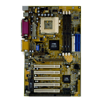
Page 6: 1-8.1 Motherboard Layout
65FVB/65FVB-X 1-8.1 MOTHERBOARD LAYOUT --- 65FVB • DEFAULT SETTING: Celeron 300/66MHz, Pentium II / Pentium !!! 450/ 100MHz. CFAN1 Clock Generator 693A 8 7 6 5 4 3 2 1 SFAN1 Controller PCI 1 PCI 2 596B JVGA1 PCI 3 PCI 4 PCI 5 Battery... -
Page 7: 1-8.2 Motherboard Layout
65FVB/65FVB-X 1-8.2 MOTHERBOARD LAYOUT --- 65FVB-X • DEFAULT SETTING: Celeron 300/66MHz, Pentium II / Pentium !!! 450/ 100MHz. CFAN1 Clock Generator 693A 8 7 6 5 4 3 2 1 SFAN1 Controller PCI 1 PCI 2 596B JVGA1 PCI 3 PCI 4 PCI 5 Battery... -
Page 8: Chapter 2: Hardware Setup
65FVB/65FVB-X Chapter 2: Hardware Setup 2-1 CPU INSTALLATION 1. Pull the lever sidways away from the socket, and then raise the lever up to a 90-degree angle. 2. Take note of the red circle as below picture. When insert the CPU into socket, you can find out there is a definite pin orientation for CPU and socket. - Page 9 65FVB/65FVB-X 3. Make sure that the CPU positions in the socket tightly, and then put the lever down to complete the CPU installation.
-
Page 10: Cpu Type Configuration
65FVB/65FVB-X 2-2 CPU TYPE CONFIGURATION BUS RATIO SELECT SW1 DIP1 ~ DIP4 SETTING 3.0x 3.5x 8 7 6 5 4 3 2 1 8 7 6 5 4 3 2 1 4.0x 4.5x 8 7 6 5 4 3 2 1 8 7 6 5 4 3 2 1 5.0x 5.5x... - Page 11 65FVB/65FVB-X CPU MODEL BUS RATIO BUS CLOCK Pentium III 533EB/133 (133MHz * 4.0x) 8 7 6 5 4 3 2 1 8 7 6 5 4 3 2 1 Celeron 300/66 (66MHz * 4.5x) Pentium III 600EB/133 (133MHz * 4.5x) 8 7 6 5 4 3 2 1 8 7 6 5 4 3 2 1 Celeron 333/66...
-
Page 12: System Memory Configuration
65FVB/65FVB-X 2-3 SYSTEM MEMORY CONFIGURATION • This VIA 693 Apollo Pro Plus motherboard supports 168pin DIMM of 4MB, 8MB, 16MB, 32MB, 64MB, 128MB, and 256MB to form a memory size between 8MB up to 768MB (SDRAM). VIA 693 Apollo Pro Plus chipset provides “Table-Free”... - Page 13 65FVB/65FVB-X JP2: KEYBOARD POWER ON Disabled (default) Enabled NOTE: When the keyboard power on function shows any compatible problem, choose Disabled and report to the keyboard vendor/ manufacturer, JP3/JP4/JP5: CPU SELECT Intel CPU (default) VIA Cyrix III (Joshua) CPU JP8/JP9: VOICE DIAGNOSTIC LANGUAGE SELECT Chinese Language English Language (default) Japanese Language...
- Page 14 65FVB/65FVB-X JP12: POWER LOST RESUME Enabled JP12 Normal (default) JP12 NOTE: This jumper allows user to use the switch of ATX power supply to control ON/OFF switch directly instead of using the power switch on the motherboard. JBAT1: CLEAR CMOS DATA Clear CMOS Data JBAT1 Retain Data (default)
-
Page 15: Connectors
65FVB/65FVB-X 2-5 CONNECTORS A1 A2 A1 : 1st HDD LED A2 : 2nd HDD LED B : INFRARED (IR) C : POWER SWITCH D : SMI E : SPEAKER F : RESET SWITCH G : POWER LED H : KEYLOCK : SUSPEND LED A : PS/2 MOUSE B : USB O... -
Page 16: 2-5.1 J1 Switch Signal Summary
65FVB/65FVB-X 2-5.1 J1 SWITCH SIGNAL SUMMARY 1 2 3 4 5 6 7 8 9 10 11 12 13 14 15 HDD LED CONNECTOR PIN 1 PIN 2 HDD LED SIGNAL PIN 3 HDD LED SIGNAL PIN 4 This connector supplies power to the cabinet's IDE activity LED. - Page 17 65FVB/65FVB-X 1 2 3 4 5 6 7 8 9 10 11 12 13 14 15 ATX POWER SWITCH PIN 12 ATX POWER SWITCH PIN 13 The system power is controlled by a momentary switch connected to this lead. Pressing the button once will switch the system between ON and SOFT OFF.
-
Page 18: 2-5.2 J2 Switch Signal Summary
65FVB/65FVB-X 2-5.2 J2 SWITCH SIGNAL SUMMARY 1 2 3 4 5 6 7 8 9 10 11 12 13 14 15 SPEAKER CONNECTOR PIN 1 SPEAKER SIGNAL PIN 2 NONE PIN 3 PIN 4 This SPEAKER connector connects to the case- mounted speaker. - Page 19 65FVB/65FVB-X 1 2 3 4 5 6 7 8 9 10 11 12 13 14 15 SUSPEND LED PIN 14 SUSPEND LED SIGNAL PIN 15 DESCRIPTION Connect to Suspend indicator light.
-
Page 20: 2-5.3 Atx Power Supply Connector
65FVB/65FVB-X 2-5.3 ATX POWER SUPPLY CONNECTOR • This connector connects to an ATX power supply. The plug from the power supply only inserts in an orientation because of the different hole sizes. Find the proper orientation and push down firmly making sure that all pins are aligned. -
Page 21: 2-5.5 Irq Description
65FVB/65FVB-X 2-5.5 IRQ DESCRIPTION Function Description Priority IRQ 0 System Timer IRQ 1 Keyboard Controller IRQ 2 Programmable Interrupt IRQ 3 Serial Port (COM 2) IRQ 4 Serial Port (COM 1) IRQ 5 IRQ 6 Floppy Disk Controller IRQ 7 Parallel Port (LPT1) IRQ 8 Real Time Clock (RTC) -
Page 22: Voice Diagnostic Function
65FVB/65FVB-X 2-6 VOICE DIAGNOSTIC FUNCTION --- 65FVB-X • The Voice Diagnostic Function user with indispensable assist on troublieshooting while assembling your computer components. If there is any conflict or other potential problem triggers a boot-up failure, this voice controller chip will voice you relistically where the conflict/problem is, then user can remove the malfunction quickly. -
Page 23: Chapter 3: Bios Setup
65FVB/65FVB-X Chapter 3: BIOS Setup • This 693 Apollo Pro Plus motherboard comes with the AWARD BIOS from AWARD Software Inc. Enter the Award BIOS program Main Menu by: 1. Turn on or reboot your system. After a series of diagnostic checks, the following message will appear: PRESS <DEL>... -
Page 24: Standard Cmos Setup
65FVB/65FVB-X 3-1 STANDARD CMOS SETUP • Standard CMOS Setup allows you to record some basic system hardware configuration and set the system clock and error handling. You only need to modify the configuration values of this option when you change your system hardware configuration or the configuration stored in the CMOS memory gets lost or damaged. - Page 25 65FVB/65FVB-X Date (mm:dd:yy) Set the current date and time. Time (hh:mm:ss) Primary / Secondary This field records the specifications for all non-SCSI Master / Slave hard disk drives installed in your system. Refer to the respective documentation on how to install the drives. Drive A / Drive B Set this field to the type(s) of floppy disk drive(s) in- stalled in your system.
-
Page 26: Bios Features Setup
65FVB/65FVB-X 3-2 BIOS FEATURES SETUP • BIOS FEATURES SETUP allows you to improve your system performance or set up sysem features according to your preference. Run the BIOS FEATURES SETUP as following: 1. Choose “BIOS FEATURES SETUP” from the Main Menu and a screen with a list of option will appear: ROM PCI/ISA BIOS BIOS FEATURES SETUP... - Page 27 65FVB/65FVB-X Virus Warning Enabled: Activates automatically when the system boots up causing a warning message to appear if there is anything attempting to access the boot sector or hard disk parti- tion table. Disabled: No warning message will appear when there is something attempting to access the boot sector or hard disk partition table.
- Page 28 65FVB/65FVB-X IDE HDD Block Mode Choose Enabled (default) or Disabled. If your hard disk size is larger than 540MB, then choose Enabled. If you are using the IDE HDD AUTO DETECTION option, the BIOS will choose this option automatically. NOTE: Some older model HDDs do not provide this feature.
- Page 29 65FVB/65FVB-X Report No FDD For Yes : BIOS reports “NO FDD” to Win95. WIN95 No (default): BIOS will not report “NO FDD” to Win95. Video BIOS Shadow Enabled copies Video BIOS to shadow RAM for im- proving performance. The choice: Enabled (default), Disabled. C8000-CBFFF to These options are used to shadow other expansion DC000-DFFFF Shadow...
-
Page 30: Chipset Features Setup
65FVB/65FVB-X 3-3 CHIPSET FEATURES SETUP • CHIPSET FEATURES SETUP allows you to change the values of chipset registers. These registers control the system options. Run the CHIPSET FEATURES SETUP as following: 1. Choose “CHIPSET FEATURES SETUP” from the Main Menu and a screen with a list of option will appear: ROM PCI/ISA BIOS CHIPSET FEATURES SETUP... - Page 31 65FVB/65FVB-X Bank 0/1 2/3 4/5 DRAM This item allows you to select the value in this field, Timing depending on whether the board has paged DRAMs or EDO (Extended Data Output) DRAMs. The choice: EDO 50ns, EDO 60ns, Slow, Medium, Fast, Turbo.
- Page 32 65FVB/65FVB-X AGP-2X Mode This item allows you to enable / disable the AGP-2X (Clock 133MHz) mode. OnChip USB This should be enabled if our system has a USB in- stalled on the system board and you wish to use it. Even when so wquipped, if you add a higher perfor- mance controller, you will need to disable this feature.
-
Page 33: Power Management Setup
65FVB/65FVB-X 3-4 POWER MANAGEMENT SETUP • POWER MANAGEMENT SETUP allows you to set the system’s power saving functions. Run the POWER MANAGEMENT SETUP as following: 1. Choose “POWER MANAGEMENT SETUP” from the Main Menu and a screen with a list of option will appear: ROM PCI/ISA BIOS POWER MANAGEMENT SETUP AWARD SOFTWARE, INC. - Page 34 65FVB/65FVB-X ACPI Function Enabled: Turn on ACPI function. Disabled (default): Turn off ACPI function. Power Management Choose Max. Saving, User Define (default), Disabled or Min. Saving. PM Control by APM When enabled, an Advanced Power Management device will be activated to enhance the Max. Power Saving mode and stop the CPU internal clock, If Ad- vanced Power Management (APM) is installed on your system, selecting Yes gives better power savings.
- Page 35 65FVB/65FVB-X Standby Mode / These two options allow you to choose the mode for Suspend Mode the different timers. The Standby Mode turns off the VGA monitor, and the Suspend Mode turns off the CPU and saves the energy of the system. HDD Power Down Time is adjustable from 1 to 15 minutes.
- Page 36 65FVB/65FVB-X The following is a list of IRQ’s (Interrupt ReQuests), which can be exempted much as the COM ports and LPT ports above can. When an I/O device wants to gain the attention of the operating system, it signals this by causing an IRQ to occur.
-
Page 37: Pnp / Pci Configuration Setup
65FVB/65FVB-X 3-5 PNP / PCI CONFIGURATION SETUP • PNP/PCI CONFIGURATION SETUP allows you to set the system’s power saving functions. Run the PNP/PCI CONFIGURATION SETUP as following: 1. Choose “PNP/PCI CONFIGURATION SETUP” from the Main Menu and a screen with a list of option will appear: ROM PCI/ISA BIOS PNP/PCI CONFIGURATION AWARD SOFTWARE, INC. - Page 38 65FVB/65FVB-X PNP OS Installed Yes: OS supports Plug and Play function. No (default): OS doesn’t support Plug and Play function. NOTE: BIOS will automatically disable all PnP resources except the boot device card when you select Yes on Non-PnP operating system. Resource Controlled Choose Manual (default) or Auto.
-
Page 39: Load Setup Defaults
65FVB/65FVB-X 3-6 LOAD SETUP DEFAULTS • LOAD SETUP DEFAULTS option loads the default system values to the system configuration fields. If the CMOS is corrupted, the defaults are loaded automatically. Choose “LOAD SETUP DEFAULTS” and the following message will appear: “... -
Page 40: Cpu Speed Setting
65FVB/65FVB-X 3-7 CPU SPEED SETTING • CPU SPEED SETTING option allows you to get some informations inside your system when it is working. Run the CPU SPEED SETTING as following: 1. Choose “CPU SPEED SETTING” from the Main Menu and a screen with a list of option will appear: ROM PCI/ISA BIOS CPU SPEED SETUP... - Page 41 65FVB/65FVB-X Auto Detect DIMM / Choose Disabled (default) or Enabled. The clock gen- PCI Clock erator will turn off the DIMM clock if this slot is empty. Spread Spectrum Choose Disabled (default) or Enabled. This function is designed to EMI test only. CPU Host Clock (CPU / Select the CPU Host Clock.
-
Page 42: Integrated Peripherals
65FVB/65FVB-X 3-8 INTEGRATED PERIPHERALS • INTEGRATED PERIPHERALS option allows you to get some informations inside your system when it is working. Run the INTEGRATED PERIPHERALS as following: 1. Choose “INTEGRATED PERIPHERALS” from the Main Menu and a screen with a list of option will appear: ROM PCI/ISA BIOS INTEGRATED PERPHERALS AWARD SOFTWARE, INC. - Page 43 65FVB/65FVB-X OnChip IDE Channel The chipset contains a PCI IDE interface with sup- 0 / 1 port from two IDE channels. Select Enabled to acti- vate the first and/or the second IDE interface. Select Disabled to deactivate an interface if you install a pri- mary and/or second add-on IDE interface.
- Page 44 65FVB/65FVB-X Onboard Serial Select an address and corresponding interrupt for the Port 1 / Port2 first and second serial ports. The choice: 3F8/IRQ4, 2E8/IRQ3, 3E8/IRQ4, 2F8/ IRQ3, Disabled, Auto. UART Mode Select This item allows you to select UART mode. The choice: Enabled, Disabled.
- Page 45 65FVB/65FVB-X KB Power ON When user sets a password for keyboard, the pass- Password word that user set returns the system to Full On state. Hot Key Power On Boot up the system via predetermined keyboard hot key. The choice: <Ctrl> + <F1>...<F12>. 3.
-
Page 46: Supervisor / User Password
65FVB/65FVB-X 3-9 SUPERVISOR / USER PASSWORD • These two options allow you to set your sysem passwords. Normally, the supervisor has a higher ability to change the CMOS setup option than the user. The way to set up the passwords for both Supervisor and User are as follows: 1. -
Page 47: Hdd Auto Detection
65FVB/65FVB-X 3-10 HDD AUTO DETECTION • IDE HDD AUTO DETECTION option can automatically detect and find the parameters of IDE Hard Drive. Meanwhile, the informations that BIOS de- tected will record to the STANDARD CMOS SETUP screen. • The screen will request you to select a specific Hard Drive for Primary Master after you select this option.
Need help?
Do you have a question about the SL-65FVB and is the answer not in the manual?
Questions and answers