Table of Contents
Advertisement
Warning: To reduce a risk of fire or electric shock, do not expose
the indoor unit to rain or moisture.
Vicon Industries Inc. does not warrant that the functions contained in this equipment will meet your
requirements or that the operation will be entirely error free or perform precisely as described in the
documentation. This system has not been designed to be used in life-critical situations and must not be
used for this purpose.
Copyright © 2007 Vicon Industries Inc. All rights reserved.
Product specifications subject to change without notice.
Vicon and its logo are registered trademarks of Vicon Industries Inc.
VICON INDUSTRIES INC., 89 ARKAY DRIVE, HAUPPAUGE, NEW YORK 11788
TEL: 631-952-CCTV (2288) FAX: 631-951-CCTV (2288) TOLL FREE: 800-645-9116
24-Hour Technical Support: 800-34-VICON (800-348-4266)
UK: 44/(0) 1489-566300
Vicon part number 8009-8134-04-01
XX134-04-01
Camera Dome
WEB: www.vicon-cctv.com
Section 3 Rev 507
Advertisement
Table of Contents

Related Manuals for Vicon SurveyorVFT SVFT-W35


Summary of Contents for Vicon SurveyorVFT SVFT-W35
-
Page 1: Camera Dome
Vicon Industries Inc. does not warrant that the functions contained in this equipment will meet your requirements or that the operation will be entirely error free or perform precisely as described in the documentation. -
Page 3: Important Safeguards
8. Accessories - Do not place the unit on an unstable surface following repair or maintenance to verify proper operation. to avoid falling. Use only UL Listed Vicon recommended mounting 22. ESD Precaution - Take all normal electrostatic discharge accessories. -
Page 5: Fcc Notice
FCC Notice Note: Complies with Federal Communications Commission Rules & Regulations Part 15, Subpart B for a Class A digital device. WARNING This equipment generates and uses radio frequency energy and if not installed and used properly, that is, in strict accordance with the manufacturer’s instruction, may cause interference to radio and television reception. -
Page 7: Table Of Contents
Contents INTRODUCTION........................1 How to Use this Manual ..........................4 Accessory Kits..............................5 Unpacking and Inspection..........................5 SurveyorVFT Components ..........................8 Enclosure ..............................8 Camera Drive ............................8 Shroud...............................8 Lower Dome ..............................8 Housing ..............................8 Sunshield..............................8 INSTALLATION ........................10 Quick Installation – In-Ceiling Model......................11 Quick Installation – Indoor Pendant ......................12 Quick Installation –... - Page 8 REFERENCE ........................64 Coaxial Cable Recommendations ......................64 Twisted-Pair Cable............................65 1.5-inch Pipe Designation ........................... 65 TECHNICAL INFORMATION..................... 67 Camera Specifications........................... 70 VICON STANDARD EQUIPMENT WARRANTY ..ERROR! BOOKMARK NOT DEFINED. iv • Contents XX134-04-01 Rev 507 SurveyorVFT Camera Dome System...
-
Page 9: Introduction
LAN interface board allows direct plug-in to a system network hub, switch or router. Video from the camera is available to all network recorders and workstations for live view and recording. The Vicon SurveyorVFT camera dome can be used in conjunction with competitive PTZ drivers through DIP switch selection. - Page 10 Pendant 23x/276x Clear (day/night) SVFT-W23 8708-00 Outdoor/Coax Color/NTSC Pendant 23x/276x Clear (day/night) SVFT-W23C 8708-01 Outdoor/Coax Color/PAL Pendant 23x/276x Clear (day/night) SVFT-W35 9102-00 Outdoor/Coax Color/NTSC Pendant 35x/420x Clear (day/night) SVFT-W35C 9102-01 Outdoor/Coax Color/PAL Pendant 35x/420x Clear (day/night) SVFT-C22CA 8741-00 Indoor/Coax Color/NTSC...
- Page 11 Coax, UTP, Fiber ViconNet Coax, UTP, Fiber ViconNet SVFT-C22/ SVFT-C22C SVFT-P22/ SVFT-P22C SVFT-W22/ SVFT-W22C SVFT-C23/ SVFT-C23C SVFT-P23/ SVFT-P23C SVFT-W23/ SVFT-W23C SVFT-W35/ SVFT-W35C SVFT-C22CA/ SVFT-C22CA-C SVFT-P22CA/ SVFT-P22CA-C SVFT-W22CA/ SVFT-W22CA-C *Power @ 24 VAC. Introduction • 3 XX134-04-01 Rev 507 SurveyorVFT Camera Dome System...
-
Page 12: How To Use This Manual
How to Use this Manual This manual was designed to provide the best overall instructions for the installation and operation of the SurveyorVFT Camera Dome. The graphics and terminology used in this manual have been carefully selected to enable a clear and distinct understanding of the SurveyorVFT and its components. This manual has been formatted to present distinct methods of installation for qualified service personnel only. -
Page 13: Accessory Kits
Installation section for details on applying the lubricant. Unpacking and Inspection All Vicon equipment is tested and inspected before leaving the factory. It is the carrier’s responsibility to provide suitable delivery. Inspect the cartons upon delivery and, if damage is present, make detailed notes on the carrier’s bill. Then, obtain the carrier agent’s signature and file a damage claim as soon as possible. - Page 14 Unpacking the SurveyorVFT In-Ceiling Unpacking the SurveyorVFT Indoor Pendant 6 • Introduction XX134-04-01 Rev 507 SurveyorVFT Camera Dome System...
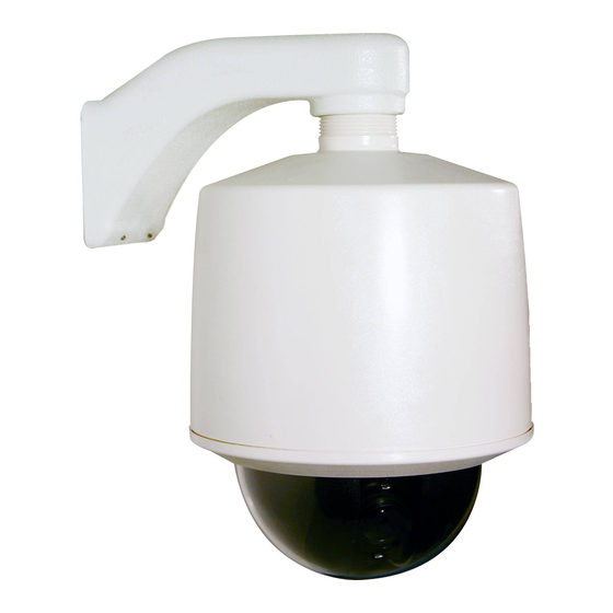
- Page 15 Unpacking the SurveyorVFT Outdoor Pendant Introduction • 7 XX134-04-01 Rev 507 SurveyorVFT Camera Dome System...
-
Page 16: Surveyorvft Components
SurveyorVFT Components All SurveyorVFT units are comprised of an Enclosure/Housing, a Camera Drive, a Shroud and a Lower Dome. Figures 1, 2 and 3 show In-Ceiling, Indoor Pendant and Outdoor Pendant models, respectively. Enclosure The enclosure is a metal shell that houses the camera drive for the in- ceiling model. - Page 17 Figure 2 SurveyorVFT Indoor Pendant Figure 3 SurveyorVFT Outdoor Pendant Introduction • 9 XX134-04-01 Rev 507 SurveyorVFT Camera Dome System...
- Page 18 10 • Introduction XX134-04-01 Rev 507 SurveyorVFT Camera Dome System...
-
Page 19: Installation
Installation Choose the installation type based on the specific unit purchased (In-Ceiling, Indoor or Outdoor Pendant). Quick Installation – In-Ceiling Model Installation • 11 XX134-04-01 Rev 507 SurveyorVFT Camera Dome System... -
Page 20: Quick Installation - Indoor Pendant
Quick Installation – Indoor Pendant 12 • Installation XX134-04-01 Rev 507 SurveyorVFT Camera Dome System... -
Page 21: Quick Installation - Outdoor Pendant
Quick Installation – Outdoor Pendant Installation • 13 XX134-04-01 Rev 507 SurveyorVFT Camera Dome System... -
Page 22: Detailed Installation
Detailed Installation These steps provide the most thorough and accurate instructions. In-Ceiling Mount Model This version of SurveyorVFT mounts in the ceiling and rests on the ceiling material occupying the space between the lower ceiling and upper building frame. All mounting hardware is provided. Use of the Provided Scribe A small metal scribe is provided to assist in marking an accurate hole size in a ceiling tile for in-ceiling installations. - Page 23 The accessory kit contains the removable screw terminal blocks to be used for all connections in this installation. The ceiling material must provide a surface of suitable strength for the SurveyorVFT weight of 5.1 lb (2.3 kg) on the area of the two flippers. Refer to the Optional Independent Support sub- section for installations requiring additional support.
- Page 24 Note: There should be minimal wire slack at all connection points. a) Strip approximately 1 inch (25 mm) of cable outer jacket to be terminated in terminal blocks. Then strip approximately 0.25 inches (6 mm) of insulation off of each individual wire. b) Refer to Wiring section and Tables 2A, 2B and 2C to make all connections to terminal blocks TB1 (power), TB2 (alarms), TB3 (relays/control signals) and TB4 (UTP video).
- Page 25 9. Connect the enclosure’s safety cord clip to the tab in the camera drive to allow the drive to hang from the enclosure. Refer to Figure 7 for location of tab. Insert the clip of the safety cord on the lower dome into the hole in the enclosure.
-
Page 26: Optional Independent Support
Optional Independent Support If it is necessary to provide independent support for the SurveyorVFT, other than the ceiling material, order the optional In-Ceiling Model Mount Kit SVFT-IC-KT. It consists of a pre-assembled set of mounting rails and folding ring, as shown in Figure 9. 1. -
Page 27: Indoor Pendant Model
Indoor Pendant Model The indoor pendant model mounts on a Vicon mount (refer to the table in the Introduction section) or a 1.5- inch vertical pipe with an appropriate coupling. The pipe is a standard 1.5-inch NPT type and must be oriented vertically so the SurveyorVFT can effectively hang from the pipe. - Page 28 Figure 12 Unlatching the Customer Interface Board b) Refer to Wiring section and Tables 2A, 2B and 2C to make all connections to terminal block TB1 (power), TB2 (alarms), TB3 (relays/control signals) and TB4 UTP video). On TB3, the COMMAND IN + (COMM IN +) and COMMAND IN - (COMM IN -) connections must be used for Simplex operation.
- Page 29 12. Lift the SurveyorVFT camera drive up to the housing and attach the housing’s safety cord clip to the camera drive’s tab. See Figure 13. Allow the drive to hang from the housing. Insert the clip of the safety cord from the lower dome into the hole on the inside of the housing.
-
Page 30: Outdoor Pendant Model
Outdoor Pendant Model The Outdoor Pendant model mounts on a Vicon mount (refer to the table in the Introduction section) or a 1.5- inch vertical pipe with appropriate coupling in the same manner as the indoor version. The outdoor version includes a sunshield, heater and weather protection. - Page 31 a) Strip approximately 1 inch (25 mm) of the cable outer jacket to be terminated in terminal blocks TB1 and TB3. Then strip approximately 0.25 inches (6 mm) of insulation off of each individual wire. b) Refer to Wiring section and Table 2 to make all connections to terminal block TB1 (power), TB2 (alarms), TB3 (relays/control signals) and TB4 UTP video).
- Page 32 14. Push the camera drive straight into housing until it snaps into the housing. Do not use excessive force. In the event that it does not snap easily, remove the SurveyorVFT and verify proper cabling. 15. Holding the lower dome, line up the 2 molded tabs on the lower dome with the 2 parallel surfaces of...
- Page 33 Figure 18 Outdoor Lower Dome Installation Installation • 25 XX134-04-01 Rev 507 SurveyorVFT Camera Dome System...
- Page 34 NOTES 26 • Installation XX134-04-01 Rev 507 SurveyorVFT Camera Dome System...
-
Page 35: Wiring
Table 4 of the Technical Information section. Refer to the table in the Introduction for power supplies available from Vicon (single and multi-channel). In the standard version, video cables carry the composite video signal and Vicoax signals out of the SurveyorVFT over coaxial cable. - Page 36 Figure 19 Customer Interface Board Connections 28 • Wiring XX134-04-01 Rev 507 SurveyorVFT Camera Dome System...
-
Page 37: Typical Relay And Alarm Connections
Typical Relay and Alarm Connections Alarm input and relay output type signals are also carried on individually-shielded twisted-pair cable sets. The signals are defined in the following descriptions. Alarms 1-4 are electronic CMOS level type inputs that are driven by a dry contact type switch. These signals are connected to terminal block TB2. -
Page 38: Installing The Cables
Installing the Cables WARNING: Disable the AC power to prevent installer injury and damage to the unit. Cables are installed using 2 different methods, depending on the installation type. For the in-ceiling installation, cables are routed from above the ceiling through a conduit fitting on the enclosure to the customer interface board. -
Page 39: For An Indoor Or Outdoor Pendant Model Installation
For an Indoor or Outdoor Pendant Model Installation Refer to Figure 19 customer interface boards for indoor or outdoor pendant model mount cable installation details. 1. Route each cable from the inside top of the housing. 2. Remove terminal blocks from the accessory kit. The 2-pin is for power, the two (2) 8-pin are for alarms and control/relay;... - Page 40 CONNECTOR/PIN CONNECTOR TYPE CONNECTOR/PIN LABEL SIGNAL NAME NUMBER BNC (female) VIDEO (J1) Video output VIDEO AMP Header (Fiber Optic board)* Video/RS-422 data TERMINAL BLOCK POWER (TB1) TB1-1 TB1-2 Neutral TERMINAL BLOCK ALARM (TB2) TB2-1 Alarm input 1 ALARM 1 TB2-2 Ground TB2-3 ALARM 2...
- Page 41 CONNECTOR/PIN CONNECTOR TYPE CONNECTOR/PIN LABEL SIGNAL NAME NUMBER TERMINAL BLOCK VIDEO NVT (TB4) TB4-1 UTP + Unshielded twisted pair + TB4-2 UTP - Unshielded twisted pair - TB4-3 TERMINAL BLOCK POWER (TB1) TB1-1 TB1-2 Neutral TERMINAL BLOCK ALARM (TB2) TB2-1 Alarm input 1 ALARM 1 TB2-2...
- Page 42 CONNECTOR/PIN CONNECTOR TYPE CONNECTOR/PIN LABEL SIGNAL NAME NUMBER TERMINAL BLOCK POWER (TB1) TB1-1 TB1-2 Neutral TERMINAL BLOCK ALARM (TB2) TB2-1 ALARM 1 Alarm input 1 TB2-2 Ground TB2-3 ALARM 2 Alarm input 2 TB2-4 Ground TB2-5 ALARM 3 Alarm input 3 TB2-6 Ground TB2-7...
-
Page 43: Installation Configurations
The star configuration requires the use of a Distribution Line Control, such as Vicon’s V1400X-IDL that can support up to 10 domes. Refer to the figure below for an illustration of sample configurations. Both types of configurations can be used within a system. -
Page 44: Installing The Flash Upgrade And Pc Direct Control
Additionally, software for the PC must be ordered; the disk provides both the flash upgrade utility, needed to upgrade the firmware in the dome to latest version, and the PC Direct Control Software, which allows a host PC to control several domes through a GUI. Call Technical Support at 1-800-34-VICON (1-800-348-4266). Standalone Configuration Vicon recommends the standalone configuration, connecting the output of the RS-232/RS-422 converter directly to the SurveyorVFT data line. -
Page 45: Star Configuration
Standalone Configuration System Star Configuration When multiple domes are connected in a star configuration, using a V1400X-IDL, the RS-232/RS-422 Interface Converter is used, part number 1240-5308-01, along with a customer fabricated cable. Refer to Table 2A for connections. In this configuration, connect the converter end of the customer-fabricated cable assembly to the SERIAL port of the computer and the other end to the CPU/J11 port on the V1400X-IDL (you may have to disconnect the keypad). - Page 46 Star Configuration System After the physical connections are made, insert the software disk and select the appropriate program, Flash Upgrade Utility or PC Direct Control Software. 38 • Wiring XX134-04-01 Rev 507 SurveyorVFT Camera Dome System...
-
Page 47: Configuration
Configuration The SurveyorVFT must be configured for its address and mode and termination setting when using RS- 422/RS-485 protocol. The address and mode are set using the two 8-position DIP Switch banks SW1 and SW2. It is necessary to determine which communication mode, Camera/Lens Module type and SurveyorVFT address is required prior to configuration. - Page 48 NOTE: DIP switches labeled ON or CLOSED and OFF or OPEN have the same meaning. Competitive Protocol Settings, Switches 5-8 Pelco: Switch 5 is ON, switches 6-8 are OFF Sensormatic: Switch 6 is ON, switches 5, 7, 8 are OFF Ultrak: Switches 5 and 6 are ON, switches 7-8 are OFF Philips: Switch 7 is ON, switches 5, 6, 8 are OFF Cohu: Switches 5 and 7 are ON, switches 6 and 8 are OFF...
- Page 49 DIP Switch 1 (SW1) Address (NOVA/VPS Mode) SWITCHES SWITCHES SWITCHES Table 3 DIP Switch 1 (SW1) Settings for NOVA/VPS Mode Configuration • 41 XX134-04-01 Rev 507 SurveyorVFT Camera Dome System...
-
Page 50: Setting The End-Of-Line Jumpers Jp1, Jp2 & Jp3 For Rs-485 Protocol Operation
Setting the End-of-Line Jumpers JP1, JP2 & JP3 for RS-485 Protocol Operation This section defines setting the end-of-line jumpers JP1, JP2 and JP3. The jumper sockets are located on the underside of the customer interface board, as shown in Figure 24. Figure 24 End-of-Line Jumper Location NOTE: DIP Switch 2 (SW2) switch 4 must be set to the ON (RS-485) position for proper daisy chain... -
Page 51: Configuring The Network Settings
When adding a SurveyorVFT IP Camera to the ViconNet network, the following items must be considered: • The number of cameras on a switch with respect to switch capabilities and system bandwidth mapping. • Bandwidth limitations on ports connected to workstations (using 100 or 1000 Mbps). •... - Page 52 Setup TAB Note: Since the Setup configuration affects the entire installation process, it MUST be configured first. In the Setup TAB, 3 fields are defined. The Upgrade files field indicates the installation upgrade directory. The Log files field allows the user the ability to put a copy of log files in a predefined directory. Password management selects a directory to save all password files.
-
Page 53: Upgrading Software Version
Select Unit TAB The Unit TAB allows the user to change the following settings: Unit name, Nucleus IP address, IP address, Net mask, Gateway, DNS, DHCP, Time Zone, daylight saving time, Local time, Local date, and Debug level, on a scale of 0-4, where 4 is most information. Note: The Apply button must be pressed for changes to take effect. -
Page 54: Advanced Tab
Install TAB The Install TAB allows the user to install/upgrade newer versions. Install Info Tab The Info TAB displays the selected IP product general information/ Info Advanced TAB The Advanced TAB functionalities allow the user to handle unexpected events on a specific remote unit when they occur. -
Page 55: Viconnet Configuration
Advanced After the SurveyorVFT has been configured for ViconNet, upon another boot up (or preset 97), the opening screen will display (see below). This screen displays the camera dome program version, current date/time and some of the word ViconNet. Upon completion of homing, the SurveyorVFT is ready to verify proper operation. -
Page 56: Viconnet (Ip/Lan) Version Operation
Open the Network Setup and Site Name setup window. Network Settings window will display. See Figure below. Change the required parameters and click OK. (See your IT administrator for specific network parameters.) Application of the camera will restart. Network Settings Window •... -
Page 57: Uninstalling The Surveyorvft
Uninstalling the SurveyorVFT The SurveyorVFT camera drive can be easily uninstalled by simply pushing in the tabs to release the camera drive from the housing or the enclosure. A safety cord is always available to safely hang the camera drive or camera dome assembly while installing or uninstalling. -
Page 58: Operation
When initial power-up has been completed and verified, SurveyorVFT can be setup and operated in a normal fashion using a Vicon remote operator keypad, VPS/NOVA unit or through a PC running the Surveyor Direct Control program; the ViconNet can be run from a ViconNet workstation. -
Page 59: Verifying Proper Operation
SurveyorVFT. Power-on the control device and verify that it boots up. Set up the control device for operation with the SurveyorVFT in accordance with its Installation and Operation Manual. For a Vicon model V1300X-RVC or V1300X-DVC keypad connected directly to the SurveyorVFT or through a CPU, use the following procedure to access SurveyorVFT programming: 1. -
Page 60: Troubleshooting
2. Press the PP ENTER key; the PRESET LED displays a blinking 0. 3. Press the 9 and 5 numeric keys in that order. 4. Press the PP ENTER key again. The PRESET LED display remains with the number 95. The monitor will display the power-up test screen (Figure 26) for the duration of its initial testing. -
Page 61: Competitive Protocols
Note: All companies make changes and improvements in their products. Because this product can interface with equipment not manufactured by Vicon, there is a possibility that the interface protocols may have changed since Vicon tested this product with the interfacing equipment. Vicon recommends purchasing a single unit for bench testing prior to purchasing and installing this product in quantity. - Page 62 Pelco 54 • Competitive Protocols XX134-04-01 Rev 507 SurveyorVFT Camera Dome System...
- Page 63 Focus Far Debug Screen Focus Far The controller MPT9500 doesn't support Pelco tours. Vicon's tours are accessible using presets 80-87 or the menu system. To store a tour, Enter preset number, Preset Set , F2. To run tour use Zoom Out Preset Tours Preset Go.
- Page 64 Repeat Pattern to repeat. Camera Off Not Supported Night Mode- Manual Not Supported Vicon Menu Alarms are not used. Alarms are alw ays enabled. The dome w ill report to the AD keypad w hich alarm is activated (1-4) Camera On...
- Page 65 Kalatel Function Keypress Function Keypress Press Set until "Enter Programming Code" appears. Enter Access Code 951followed by SEQ. Select 4 - Cyberdome. Enter three digit camera number. Enter 1 when prompted "Does The Monitor Display Site XXX". Enter Menu Program the unit using the joystick. Set Transmit Polarity Not Supported Not Supported;...
- Page 66 Ultrak When changing SurveyorVFT software addresses, the keypad may not respond to all 256 addresses. The workaround is to go to Ultrak KEGS Setup menu, option (3.1.2) and set every camera (256) to KD6. Function Keypress Function Keypress Enter SVFT-M address on keypad and hit Enter key.
- Page 67 Panasonic Function Keypress Function Keypress Press and hold CAMERA SETUP button for 2 sec. Use SET button to select and save options. Use ESC button to abort or leave options. Move joystick up and down to select and highlight SurveyorVFT preset 94 menu options. Use button AUX 1 for Aux 1 and AUX 2 for Aux 2.
- Page 68 Philips Function Keypress Function Keypress Use On-46-Enter shortcut to enter Dome menu. Use Focus Far button to select and save options. Use Iris Close button to abort or leave options. Move joystick up and down to select and highlight Dome menu options (joystick does not support "press and hold"...
- Page 69 Cohu Function Keypress Function Keypress To launch Dome menu use Preset 64 + Store. Use Focus Far button to select and save options. Use Iris Close button to abort or exit options. Move mouse cursor up and down on Not Supported Pan/Tilt pane to select and highlight Dome menu options.
-
Page 70: Maintenance
Maintenance The SurveyorVFT requires no scheduled maintenance; however, the Lower Domes require occasional cleaning. The Chrome and Gold Domes are referred to as Metallized type domes. The Clear and Smoked Domes are referred to as Acrylic type domes. All domes require careful handling and occasional cleaning. Care and Cleaning of Metallized Domes 1. -
Page 71: Shipping Instructions
Shipping Instructions Use the following procedure when returning a unit to the factory: 1. Call or write Vicon for a Return Authorization (R.A.) at one of the locations listed below. Record the name of the Vicon employee who issued the R.A. -
Page 72: Reference
Coaxial Cable Recommendations Caution: Careful selection of proper cable is essential to obtain the best performance from this equipment. Vicon assumes no responsibility for poor performance when cables other than those recommended, or equivalent, are installed. In all cases, coaxial cable impedance should be 75 ohms. -
Page 73: Twisted-Pair Cable
Table Recommended Individually-Shielded, Twisted-Pair Cable Types UTP Connection For NVT models, where video is transmitted over twisted-pair cable, a UTP receiver is required. Vicon offers three receivers to provide video transmission over a range of distances. NVT Receiver Wire Gauge... -
Page 74: Network Cable
Network Cable Caution: Careful selection of proper cable is essential to obtain the best performance. Vicon assumes no responsibility for poor performance when cables other than the recommended types, or equivalent, are used. Materials Use pure copper stranded conductors to obtain a low DC resistance. The preferred insulation and cable jacket is Polyvinyl chloride (PVC). -
Page 75: Technical Information
Technical Information Zoom and Focus Speed: Less than 1.8 sec from end to end. ELECTRICAL Drive Type: Electrical motorized pan and tilt Sectoring: 16 max, programmable for size and with electronic control. titling; capability to be blanked out Camera Types: (22XEX/23X/35X only). - Page 76 22X). Because this product can interface with equipment not manufactured by Multilanguage Menu: English, Spanish, French, German Vicon, there is a possibility that the and Italian. interface protocols have Day/Night (23X) Features: 6 programmable motion detection changed since Vicon tested this zones with 3 sensitivity levels;...
- Page 77 In-ceiling or indoor/outdoor pendant. Rain/Wind: Housing Types: winds up to 90 mph, when mounted Indoor pendant housing and outdoor on standard Vicon wall mount. pendant housing with sunshield. Pendant Mount Size/Thread: Standard 1-1/2 inch male NPT pipe thread or metric equivalent.
-
Page 78: Camera Specifications
Table 5: Camera/Lens Specifications Model Numbers SVFT-C22, SVFT-P22, SVFT-C22C, SVFT- SVFT-C23, SVFT-P23, SVFT-C23C, SVFT- SVFT-W22 P22C, SVFT-W22C SVFT-W23 P23C, SVFT-W23C Product Codes Camera Specifications 8701-00, 8704-00, 8701-01, 8704-01, 8702-00, 8705-00, 8702-01, 8705-01, 8707-00 8707-01 8708-00 8708-01 Formats NTSC NTSC Color Color Color Color... - Page 79 Model Numbers SVFT-C22CA, SVFT-P22CA, SVFT-W22CA/ SVFT-W35/SVFT-W35-C SVFT-C22CA-C, SVFT-P22CA-C, SVFT-W22CA-C Product Codes Camera Specifications 8741-00, 8742-00, 8743-00/ 9102-00/9102-01 8741-01, 8742-01, 8743-01 Formats NTSC/PAL NTSC/PAL Type Color Color Optical Zoom Digital Zoom Total Zoom 264X 420X OPTICAL wide/DIGITAL tele: 3.9 sec Tele-Wide: 4.6 sec...
-
Page 80: 72 • Vicon Standard Equipment Warranty
Software supplied either separately or in hardware is furnished on an “As Is” basis. Vicon does not warrant that such software shall be error (bug) free. Software support via telephone, if provided at no cost, may be discontinued at any time without notice at Vicon’s sole discretion. - Page 81 Vicon Industries Inc. Corporate Headquarters 89 Arkay Drive Hauppauge, New York 11788 631-952-CCTV (2288) 800-645-9116 Fax: 631-951-CCTV (2288) Vicon Europe Headquarters Brunel Way Fareham, PO15 5TX United Kingdom +44 (0) 1489 566300 Fax: +44 (0) 1489 566322 Germany vin-videotronic infosystems gmbh...
Need help?
Do you have a question about the SurveyorVFT SVFT-W35 and is the answer not in the manual?
Questions and answers