Table of Contents
Advertisement
INSTALLATION INSTRUCTIONS
WALL HUNG RSF GAS FIRED CONDENSING BOILER
GREENSTAR i SYSTEM OPTIONAL
INTEGRAL DIVERTER VALVE
FOR CENTRAL HEATING SYSTEMS AND INDIRECT FED DOMESTIC HOT WATER
Diverter valve kit numbers
12kW
7 716 192 566
15kW
7 716 192 567
18kW
7 716 192 568
24kW
7 716 192 409
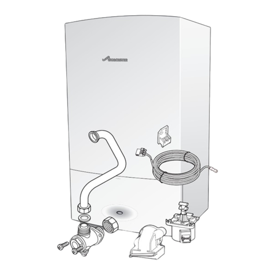
Diverter valve kits contain:
1
Copper return pipe
1
Brass service valve
1
15mm Compression nut
1
15mm Olive
1
Diverter valve motor
1
Diverter valve harness
2
Screws
2
Code plugs
1
Code plug tie
Code plug numbers
12i System
15i System
18i System
24i System
UK/IE
Natural gas
1118
L.P.G.
1119
Natural gas
1122
L.P.G.
1123
Natural gas
1126
L.P.G.
1127
Natural gas
1114
L.P.G.
1115
Advertisement
Table of Contents

Related Manuals for Worcester Gas boiler


Summary of Contents for Worcester Gas boiler
-
Page 1: Installation Instructions
INSTALLATION INSTRUCTIONS WALL HUNG RSF GAS FIRED CONDENSING BOILER GREENSTAR i SYSTEM OPTIONAL INTEGRAL DIVERTER VALVE FOR CENTRAL HEATING SYSTEMS AND INDIRECT FED DOMESTIC HOT WATER Diverter valve kit numbers 12kW 7 716 192 566 15kW 7 716 192 567 18kW 7 716 192 568 24kW... -
Page 2: Table Of Contents
CONTENTS CONTENTS KEY TO SYMBOL AND SAFETY PRECAUTIONS . 3 Explanation of symbols ....3 Safety precautions ....4 PLUMBING MANIFOLD . -
Page 3: Key To Symbols And Safety Precautions
INSTALL CORRECTLY COULD LEAD TO PROSECUTION. instructions. • NOTICE indicates possible damage to property or IF YOU ARE IN ANY DOUBT CONTACT THE WORCESTER equipment, but where there is no risk of injury. TECHNICAL HELPLINE. • CAUTION indicates possible injury. -
Page 4: Safety Precautions
KEY TO SYMBOLS AND SAFETY PRECAUTIONS SAFETY PRECAUTIONS FITTING AND MODIFICATIONS Fitting the appliance and any controls to the appliance IF YOU SMELL GAS: may only be carried out by a competent engineer in B CALL NATIONAL GAS EMERGENCY SERVICE ON accordance with the current Gas Safety (Installation and 0800 111 999 Use) Regulations. - Page 5 KEY TO SYMBOLS AND SAFETY PRECAUTIONS British Standards: Where no specific instruction is given, reference should be made to the relevant British Standard codes of Practice. BS7074:1 Code of practice for domestic and hot water supply BS6891 Installation of low pressure gas pipe work up to 28mm (R1) BS5546 Installation of gas hot water supplies for...
-
Page 6: Plumbing Manifold
PLUMBING MANIFOLD PLUMBING MANIFOLD CONNECTIONS: • Heating System: 22mm compression fittings • Gas: 22mm compression fitting • Cylinder Return 15mm compression fitting • Use the fittings supplied in the Hardware literature pack and the Optional Diverter Valve Kit. NOTICE: Fitting the service valve B Refer to figure 2 B The service valve (7) from the Optional Diverter Valve Kit must be fitted and... -
Page 7: Boiler Connections
BOILER CONNECTIONS BOILER CONNECTIONS CAUTION: CYLINDER RETURN PIPE B The following must be completed before the boiler is mounted onto the wall mounting frame ASSEMBLY OF THE INTERNAL CYLINDER RETURN PIPE TO THE BOILER Use the packaging as protection, turn the boiler on its left hand side to enable fitting of the hot water return pipe. B Move the control panel into the service position by removing the screw from the retaining bracket. -
Page 8: Gas And Water Connections
BOILER CONNECTIONS GAS AND WATER CONNECTIONS CAUTION: B ISOLATE THE MAINS GAS SUPPLY BEFORE STARTING ANY WORK AND OBSERVE ALL RELEVANT SAFETY PRECAUTIONS. B Remove template and secure the wall mounting frame to the wall with the fittings supplied. B System pipes may be run vertically upwards behind the boiler or below it. - Page 9 BOILER CONNECTIONS 1. Push the lever on the pressure relief connector UP until the stop on the inside of the handle is over the shoulder of the metal bracket to secure in place. 6720645222-05.1Wo Fig. 8 Blanking plug removal 1. Refer to figure 9 and insert the expansion vessel flexible pipe it to the fitting on the pump.
-
Page 10: Fitting The Diverter Valve & Code Plug
FITTING THE DIVERTER VALVE AND CODE PLUG FITTING THE DIVERTER VALVE AND CODE PLUG FITTING THE DIVERTER VALVE ACCESS TO THE CODE PLUG MOTOR: 1. Referring to figure 12, unscrew the three screws in the control panel. 1. Remove the diverter blanking plate by pulling it forwards to free it from its location. -
Page 11: Fitting The Code Plug
FITTING THE DIVERTER VALVE AND CODE PLUG FITTING THE CODE PLUG NOTICE: Figure 15 applies only to foam covered open vent cylinders. Boiler size Code plug no. 12kW i System kit 1118 1119 15kW i System kit 1122 1123 18kW i System kit 1126 1127 24kW i System kit... -
Page 12: Electrical
ELECTRICAL ELECTRICAL NOTICE: B Mains supply to the boiler must be through a fused double pole isolator situated adjacent to the appliance. The isolator must have a contact separation of 3mm minimum in both poles. External fuse rating 3A. B When stripping wires always ensure copper strands do not fall into the control box. B There should be no external wiring centre. -
Page 13: Internal Diverter Valve With An Unvented Cylinder
ELECTRICAL INTERNAL DIVERTER VALVE WITH AN UNVENTED CYLINDER Twin Channel Cylinder Programmer temperature sensor DUAL THERMOSTAT HIGH LIMIT HOT WATER CONTROL THERMAL CUT-OUT THERMOSTAT brown 230V green/yellow MAINS blue SUPPLY Room Thermostat neutral live switched live 6720645222-20.1Wo OPTIONAL EXTERNAL FROST STAT CONNECTION ST6 Frost Thermostat NP LP 6720643895-43.1Wo... -
Page 14: Position Of Wired Components
Blue EMS BUS contacts Blue Purple (for FX controls) Purple Orange WORCESTER 24V CONTROLS, PLUG IN POINT Orange OPTIONS: DT20 OR DT20 RF OR DT10 RF Green (under blanking cover on fascia) Fuse F3, slow T 0.5 A 230V/AC Fuse F2, slow T1.6 A... -
Page 15: Pre-Commissioning Checks
PRE-COMMISSIONING CHECKS PRE-COMMISSIONING CHECKS NOTICE: If the boiler is not to be commissioned immediately then: B after successfully completing all of the checks and any rectification work, close the gas and water valves, shut off the gas supply, electrically isolate the boiler and label appropriately. -
Page 16: Boiler Function
BOILER FUNCTION BOILER FUNCTION FAULT FINDING If in the unlikely event the boiler does not give complete satisfaction, before calling for a service engineer, the installer should check the following:- FOR BOILERS WITH INTEGRAL DIVERTER VALVE AND CONTROLS NO CENTRAL HEATING, BUT HOT WATER OK Remove the room stat wiring from Ls, LR and N from terminal block ST10. -
Page 17: Boiler Function
BOILER FUNCTION BOILER FUNCTION Fig. 21 Boiler function 6 720 645 222a (2012/05) -
Page 18: Protection Function
BOILER FUNCTION PROTECTION FUNCTION AUTOMATIC INTERNAL FROST FUNCTION Internal boiler Pump switches off Internal boiler temperature Pump runs after a 3 minute temperature between rises above 9°C overrun period 8°C & 5°C Boiler automatic frost function (monitors internal boiler primary temperature) Central heating Internal boiler Internal boiler... - Page 19 BOILER FUNCTION NOTES 6 720 645 222a (2012/05)
- Page 20 LITERATURE: 0844 892 9800 TRAINING: 01905 752526 SALES: 01905 752640 Worcester, Bosch Group Cotswold Way, Warndon, Worcester WR4 9SW. Tel. 0844 892 9900 Worcester, Bosch Group is a brand name of Bosch Thermotechnology Ltd. worcester-bosch.co.uk 6 720 645 222a (2012/05)
Need help?
Do you have a question about the Gas boiler and is the answer not in the manual?
Questions and answers