
Related Manuals for digico SD9


Summary of Contents for digico SD9
- Page 1 SD9 Operation Manual User Manual - Getting Started To be read in conjunction with the SD Series Software Reference User Manual Version B for Software Versions 4.0.680+...
- Page 2 SD9 Operation Manual...
- Page 3 SD9 Operation Manual...
-
Page 4: Sd9 Operation Manual
Licenses and Trademarks The SD9 logo and SD9 name are trademarks, and Digico UK Ltd and the Digico UK Ltd logo are registered trademarks of Digico UK Ltd. Microsoft is a registered trademark and Windows is a trademark of Microsoft Corp. -
Page 5: Table Of Contents
SD9 Operation Manual Contents 1.1 Introduction ..................1-1 1.2 Manual Overview ................1-1 1.3 Before You Start ................1-2 1.3.1 Worksurface Layout .............1-2 1.3.2 Screen Assignment ..............1-2 1.3.3 Channel Banks ..............1-3 1.3.4 Using the Control Surface ...........1-3 1.3.5 The Assigned Channel .......... -
Page 6: Introduction
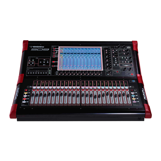
1.1 Introduction The Digico SD9 consists of a worksurface with an onboard audio engine and a range of onboard inputs and outputs. This can be connected to multiple Input/Output Rack Units by CAT5 cable or MADI links which carry all the audio input and output signals. -
Page 7: Before You Start
1.3.2 Screen Assignment ............... The SD9 has one central touchscreen which is used to access many of the console's functions. There are 3 possible views that can be seen on this screen - Left section - Right section - Master screen Each console worksurface section has its own Screen Assign button which, when pressed, will allow the channels in that section to be viewed on the screen and controlled by the Channel Processing controls such as EQ and Dynamics. -
Page 8: Channel Banks
1.3.3 Channel Banks ..............The SD9's worksurface is divided into Banks. Each Bank contains twelve channels, and the channels which are currently active on the control surface are defined using the fader bank buttons to the right and left of the faders: A ‘bank’... -
Page 9: The Assigned Channel
SD9 - Getting Started 1.3.5 The Assigned Channel ............One of the channels in the Channel Strip panel is displayed in gold, indicating that it is currently the Assigned Channel. This means that it has been assigned to the worksurface controls and can be configured in detail, as described below. To Assign a channel, touch anywhere in the channel on the screen. -
Page 10: The Master Fader
1.3.8 Channel Types ..............The signal flow of the SD9 is best understood in terms of the four channel types contained within it, shown below. Each channel type offers full signal processing capabilities. As a summary, the four channel types are as follows: Input channels bring signals into the console to be mixed and sent to aux and group busses. -
Page 11: Hardware Configuration
The SD9 worksurface has 8 analogue I/O and 2 AES I/O L/R pairs on its rear panel and additional I/O is supplied in the form of a remote D-Rack which has 32 analogue inputs and 8 analogue outputs as standard. This rack is connected to the worksurface by a 75M STP CAT5e cable. -
Page 12: Audio I/O Panel
D-Rack 1 1.4.2 Audio I/O Panel..............The Audio I/O panel is used to configure the physical I/O connected to the SD9, including configuring and naming the sockets of the cards installed in racks, and the setting of Pads and phantom power. - Page 13 SD9 - Getting Started Rack Connections With a Rack selected in the left hand port selection list, the window will change to look something like the image below, depending on the cards installed in the connected rack. The graphic shows the 6 available cards/slots, 4 input & 2 output.
- Page 14 In a multi-console system where Racks are connected with MADI and shared between two DiGiCo Consoles, only one of the consoles can take control of the rack, with respect to Gain, Phantom Power and Pads. To overcome this, it is possible to place the SD9 into one of 3 states of operation;...
-
Page 15: Configuring A Session
1.5 Configuring a Session The SD9 has a default setup which means that the new user need not get involved in configuring the desk at this stage. However, here is a brief overview of how the different displays are used in putting together a session. Each of the master displays intro- duced below are described fully within the SD Series Software Reference Manual The Setup >... -
Page 16: Assigning Faders To The Worksurface
SD9 - Getting Started Clear All Buttons : When changing routing, you have the option of clearing any non-default routing or processing (EQ, dynamics etc) from the channels in the session. This is especially useful when restructuring an existing session to make a new session. -
Page 17: Saving And Loading Sessions
SD9 - Getting Started 1.6 Saving and Loading Sessions 1.6.1 Save As New File ..............When you change the configuration of the a session you should save it to the console's flash drive under a new filename. If the Save Session panel has not appeared automatically after a session restructure then touch the Files button on the Master screen and then press Save As New File. -
Page 18: Audio Sync
By default, it is set to clock internally (as a Master) and the Sample rate is determined by your selection in the Session Structure panel. Within a normal setup, the SD9 will usually remain as clock master. However, there are times when the SD9 needs to be clocked externally. -
Page 19: Routing Basics
For input and insert return routing, the INTERNAL port provides the following signal groups: Misc: The oscillator, white and pink noise generators. Graphic EQs: The outputs of the SD9’s internal graphic EQ’s. Effects: The outputs of any effects sends that have been created... -
Page 20: Ripple Channels
For output and insert send routing, the INTERNAL port provides access to the inputs of the SD9’s Graphic EQ’s, and the inputs to any effects that have been created. -
Page 21: Channel Processing
SD9 - Getting Started 1.9 Channel Processing 1.9.1 EQ ..................The EQ section comprises four user-configurable parametric filters and a pair of swept High-pass and Low-pass filters. The EQ is accessed by touching the on screen display to Assign the channel (the colour changes to gold) and then using the controls on the right hand side of the screen. -
Page 22: Dynamics
SD9 - Getting Started 1.9.2 Dynamics ................The dynamics are accessed by touching the words Comp or Gate just below the EQ graph on screen to open the dynamics panel. There are two dynamics modules, the first of which can function as a simple compressor, a 3 way multiband compressor, or a de-esser, according to the comp/multi/desser button to its left. -
Page 23: Auxiliaries
SD9 - Getting Started 1.9.3 Auxiliaries ................The auxiliaries can be accessed by touching the Aux Quick Select button, the auxiliary row on screen or using the Screen Scroll buttons. Using either of these methods, the highlighted auxiliaries on the input screen will change. The row of rotary controls and switches beneath the screen are used as auxiliary sends, pans (with 2nd Function ON), On/Off and pre/post switches (with 2nd Function ON). -
Page 24: The Matrix
Matrix Output Channels, and set the Matrix crosspoint levels. To route an input, touch the top of the appropriate Matrix column. This opens a standard SD9 input routing page with options to select any console or rack signal as a Matrix input. -
Page 25: Control Groups
SD9 - Getting Started 1.11 Control Groups Any number of input channels and output channels can be connected to one or more of the 8 Control Groups. They can then all be operated from a single worksurface channel. Changes to the Control Group fader, mute or solo or controls will affect all channels connected to the group. -
Page 26: Solo Setup
SD9 - Getting Started 1.12 Solo Setup The SD9 Solo panel is accessed from a button at the top of the Master Screen. Some of the controls on this panel are duplicated on the left worksurface section. There are two solo busses and each channel on the consoles can be independently assigned to use Solo1, Solo2 or Solo 1+2.
Need help?
Do you have a question about the SD9 and is the answer not in the manual?
Questions and answers