
Related Manuals for Decimator DMON?12S

Summary of Contents for Decimator DMON?12S
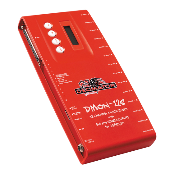
- Page 1 DMON-12S 1 to 12 Channel (3G/HD/SD)‐SDI Multi‐Viewer with SDI and HDMI outputs Operating Manual for Firmware Version 1.1 DMON‐12S Hardware Manual for Firmware Version 1.1 Copyright © 2014 Decimator Design Pty Ltd, Sydney, Australia...
- Page 2 Variable aspect ratios per quadrant Pass‐Through mode allowing any of the 12 inputs to be selected for output In Pass‐Through mode the selected input is passed through to both the (3G/HD/SD)‐SDI and HDMI outputs The DMON‐12S is a truly portable converter that incorporates our new easy to use LCD and button control system. This gives you easy access to most of the amazing features without using complicated LED/button control, dip switches or having to carry around a computer to change a simple setting. This unit also includes: ‐ 32 GPI on 37‐pin D‐SUB connector for Dynamic Tallies and Remote Switching ‐ RS422/485 on 37‐pin D‐SUB connector for Dynamic UMD and Tallies via TSL protocol ‐ USB port for control and firmware updates ‐ Heavy duty metal box ‐ Metal Thread Locking DC Power Socket ‐ Power Supply, HDMI Cable and USB Cable DMON‐12S Hardware Manual for Firmware Version 1.1 Copyright © 2014 Decimator Design Pty Ltd, Sydney, Australia...
-
Page 3: Main Menus
Current format on SDI Input 5 5:3G 1080p60 Current format on SDI Input 6 6:3G 1080p60 Current format on SDI Input 7 7:3G 1080p60 Current format on SDI Input 8 8:3G 1080p59.94 (After pressing ENTER twice) Current format on SDI Input 9 9:HD 1080p24 Current format on SDI Input 10 10:HD 720p50 Current format on SDI Input 11 11:SD 480i59.94 Current format on SDI Input 12 12:HD 1080i59.94 Control: (Has SUB‐MENUs) Main Menu <== Control Sub Menu HDMI Output Type HDMI RGB444 2C Parameter Window When highlighted in the Main Menu, press the ENTER button to enter this sub‐menu. DMON‐12S Hardware Manual for Firmware Version 1.1 Copyright © 2014 Decimator Design Pty Ltd, Sydney, Australia... - Page 4 11.) Window 10 12.) Window 11 13.) Window 12 3. Control / MV Output Format (Parameter) This is the current output format for the Multi‐Viewer. When the sub menu is highlighted, press the ENTER button to enter this sub‐menu. Press the < and > buttons to move left or right through the 26 video formats listed below and the BACK button to leave this SUB‐MENU. 1. SD 720x487i59.94 11. HD 1920x1080p30 21. HD 1280x720p25 2. SD 720x576i50 12. HD 1920x1080p29.97 22. HD 1280x720p24 3. HD 1920x1080i60 13. HD 1920x1080p25 23. HD 1280x720p23.98 4. HD 1920x1080i59.94 14. HD 1920x1080p24 24. 3G 1920x1080p60 5. HD 1920x1080i50 15. HD 1920x1080p23.98 25. 3G 1920x1080p59.94 6. HD 1920x1080psf24 16. HD 1280x720p30 26. 3G 1920x1080p50 7. HD 1920x1080psf23.98 17. HD 1280x720p29.97 4. Control / MV Windows (Parameter) This is the current number of windows shown on the multi‐view output. When the sub menu is highlighted, press the ENTER button to enter this sub‐menu. Press the < and > buttons to move left or right through the number of windows displayed from 1 to 12. Default Windows displayed is 12 windows. DMON‐12S Hardware Manual for Firmware Version 1.1 Copyright © 2014 Decimator Design Pty Ltd, Sydney, Australia...
- Page 5 3.) Window 3 4.) Window 4 5.) Window 5 6.) Window 6 7.) Window 7 8.) Window 8 9.) Window 9 10.) Window 10 11.) Window 11 12.) Window 12 7. Control / MV Reference (Parameter) This is reference for the Multi‐Viewer. When the sub menu is highlighted, press ENTER to toggle through the following sources: 1.) Window 1 2.) Free‐Run 8. Control / Pass Scaled (Parameter) When the Output Select is changed to window 1 to 12, this parameter determines whether the output is scaled or passed through unchanged from the selected window. When the output is scaled, the selected layout for window 1 is used. When the sub menu is highlighted, press ENTER to toggle through the following selections: 1.) Yes 2.) No DMON‐12S Hardware Manual for Firmware Version 1.1 Copyright © 2014 Decimator Design Pty Ltd, Sydney, Australia...
- Page 6 Main Menu <== Routing Sub Menu Window 1 Source Input 1 Parameter Window When highlighted in the Main Menu, press the ENTER button to enter this sub‐menu. Press the < and > buttons to move left or right respectively through the 12 menus below and press the BACK button to go back to the Main Menu when finished. The current value for each Sub Menu is shown in the Parameter Window. 1. Routing / Window 1 Source (Parameter) This is the input source for Window 1. When the sub menu is highlighted, press the ENTER button to enter this sub‐menu. Press the < and > buttons to move left or right through the following sources: 1.) Input 1 (default for Window 1) 2.) Input 2 (default for Window 2) 3.) Input 3 (default for Window 3) 4.) Input 4 (default for Window 4) 5.) Input 5 (default for Window 5) DMON‐12S Hardware Manual for Firmware Version 1.1 Copyright © 2014 Decimator Design Pty Ltd, Sydney, Australia...
- Page 7 4.) Cyan 5.) Red 6.) Magenta 7.) Yellow 8.) White 2. Colours / Border Colour (Parameter) This is border colour for the Multi‐Viewer. When the sub menu is highlighted, press the ENTER button to enter this sub‐menu. Press the < and > buttons to move left or right through the following colours: 1.) Black 2.) Blue 3.) Green 4.) Cyan 5.) Red 6.) Magenta 7.) Yellow 8.) White DMON‐12S Hardware Manual for Firmware Version 1.1 Copyright © 2014 Decimator Design Pty Ltd, Sydney, Australia...
- Page 8 Press the < and > buttons to move left or right through the following colours: 1. None 10. Black (Transparent 25%) 19. Blue (Transparent 0%) 2. Black (Transparent 50%) 11. Blue (Transparent 25%) 20. Green (Transparent 0%) 3. Blue (Transparent 50%) 12. Green (Transparent 25%) 21. Cyan (Transparent 0%) 4. Green (Transparent 50%) 13. Cyan (Transparent 25%) 22. Red (Transparent 0%) 5. Cyan (Transparent 50%) 14. Red (Transparent 25%) 23. Magenta (Transparent 0%) 6. Red (Transparent 50%) 15. Magenta (Transparent 25%) 24. Yellow (Transparent 0%) 7. Magenta (Transparent 50%) 16. Yellow (Transparent 25%) 25. White (Transparent 0%) 8. Yellow (Transparent 50%) 17. White (Transparent 25%) 9. White (Transparent 50%) 18. Black (Transparent 0%) DMON‐12S Hardware Manual for Firmware Version 1.1 Copyright © 2014 Decimator Design Pty Ltd, Sydney, Australia...
- Page 9 1. None 10. Black (Transparent 25%) 19. Blue (Transparent 0%) 2. Black (Transparent 50%) 11. Blue (Transparent 25%) 20. Green (Transparent 0%) 3. Blue (Transparent 50%) 12. Green (Transparent 25%) 21. Cyan (Transparent 0%) 4. Green (Transparent 50%) 13. Cyan (Transparent 25%) 22. Red (Transparent 0%) 5. Cyan (Transparent 50%) 14. Red (Transparent 25%) 23. Magenta (Transparent 0%) 6. Red (Transparent 50%) 15. Magenta (Transparent 25%) 24. Yellow (Transparent 0%) 7. Magenta (Transparent 50%) 16. Yellow (Transparent 25%) 25. White (Transparent 0%) 8. Yellow (Transparent 50%) 17. White (Transparent 25%) 9. White (Transparent 50%) 18. Black (Transparent 0%) DMON‐12S Hardware Manual for Firmware Version 1.1 Copyright © 2014 Decimator Design Pty Ltd, Sydney, Australia...
- Page 10 7. Magenta (Transparent 50%) 16. Yellow (Transparent 25%) 25. White (Transparent 0%) 8. Yellow (Transparent 50%) 17. White (Transparent 25%) 9. White (Transparent 50%) 18. Black (Transparent 0%) UMDs: (Has SUB‐MENUs) Main Menu <== UMDs Sub Menu All On Parameter Window When highlighted in the Main Menu, press the ENTER button to enter this sub‐menu. Press the < and > buttons to move left or right respectively through the 3 menus below and press the BACK button to go back to the Main Menu when finished. The current value for each Sub Menu is shown in the Parameter Window, unless it is an action Sub Menu. 1. UMDs / All On (Action) Pressing ENTER when this submenu is selected will turn all UMD overlays on. 2. UMDs / All Off (Action) Pressing ENTER when this submenu is selected will turn all UMD overlays off. 3. UMDs / UMD Justify (Parameter) This parameter determines whether the text inside the 16 character window is centred, left or right justified. When the sub menu is highlighted, press ENTER to toggle through the following options: 1.) Centre 2.) Left 3.) Right DMON‐12S Hardware Manual for Firmware Version 1.1 Copyright © 2014 Decimator Design Pty Ltd, Sydney, Australia...
- Page 11 When the sub menu is highlighted, press ENTER to toggle through the following selections: 1.) 0% 2.) 25% 3.) 50% 5. Audio Meter / Show Scale (Parameter) This indicates if the scale is shown on the audio meter overlays. When the sub menu is highlighted, press ENTER to toggle through the following selections: 1.) Off 2.) On 6. Audio Meter / Meter Scale (Parameter) This is the current scale shown on the audio meter overlays. When the sub menu is highlighted, press ENTER to toggle through the following selections: 1.) AES/EBU 2.) VU 3.) Extended VU 4.) BBC PPM (IEC 2a) 5.) EBU PPM (IEC 2b) 6.) DIN PPM (IEC 1a) 7.) NORDIC (IEC 1b) DMON‐12S Hardware Manual for Firmware Version 1.1 Copyright © 2014 Decimator Design Pty Ltd, Sydney, Australia...
- Page 12 3.) ‐15 dBFS 10. Audio Meter / Yellow Start (Has SUB‐MENU with parameter) This is the starting level for the yellow range on the audio meter. The value default is ‐10dBFS. When the sub menu is highlighted, press the ENTER button to enter this sub‐menu. Press the < and > buttons to increase and decrease the level from 0 to ‐100dBFS respectively. Press the BACK button to leave this SUB‐MENU. 11. Audio Meter / Green Start (Has SUB‐MENU with parameter) This is the starting level for the green range on the audio meter. The value default is ‐20dBFS. When the sub menu is highlighted, press the ENTER button to enter this sub‐menu. Press the < and > buttons to increase and decrease the level from 0 to ‐100dBFS respectively. Press the BACK button to leave this SUB‐MENU. Graticules: (Has SUB‐MENUs) Main Menu <== Graticules Sub Menu S.Action All On Parameter Window When highlighted in the Main Menu, press the ENTER button to enter this sub‐menu. Press the < and > buttons to move left or right respectively through the 11 menus below and press the BACK button to go back to the Main Menu when finished. The current value for each Sub Menu is shown in the Parameter Window, unless it is an action Sub Menu. 1. Graticules / S.Action All On (Action) Pressing ENTER when this submenu is selected will turn all Safe Action Graticules overlays on. 2. Graticules / S.Title All On (Action) Pressing ENTER when this submenu is selected will turn all Safe Title Graticules overlays on. 3. Graticules / C.Cross All On (Action) Pressing ENTER when this submenu is selected will turn all Centre Cross overlays on. DMON‐12S Hardware Manual for Firmware Version 1.1 Copyright © 2014 Decimator Design Pty Ltd, Sydney, Australia...
- Page 13 PIN 7 = Window 9 Tally Green PIN 20 = Ground PIN 33 = Window 12 Tally Red PIN 8 = Window 11 Tally Green PIN 21 = RS485‐ PIN 34 = Window 2 Tally Green PIN 9 = Window 1 Tally Red PIN 22 = Window 2 Tally Green PIN 35 = Window 4 Tally Green PIN 10 = Window 3 Tally Red PIN 23 = Window 4 Tally Green PIN 36 = Window 6 Tally Green PIN 11 = Window 5 Tally Red PIN 24 = Window 6 Tally Green PIN 37 = Output Select Toggle PIN 12 = Window 7 Tally Red PIN 25 = Window 8 Tally Green PIN 13 = Window 9 Tally Red PIN 26 = Window 10 Tally Green DMON‐12S Hardware Manual for Firmware Version 1.1 Copyright © 2014 Decimator Design Pty Ltd, Sydney, Australia...
-
Page 14: Load Defaults
2. SETUP / LCD OFF TIME (Parameter) This is the time taken for the LCD light to turn off after the last button press. When the sub menu is highlighted, press ENTER to toggle through the following times: 4.) 5 seconds 5.) 15 seconds 6.) 30 seconds 7.) 1 minute 8.) 5 minutes 9.) 10 minutes 10.) 30 minutes 11.) Never 3. SETUP / BACK2STATUS TIME (Parameter) This is the time before the main menu is returned to Input Status after the last button press. When the sub menu is highlighted, press ENTER to toggle through the following times: 1.) 5 seconds 2.) 15 seconds 3.) 30 seconds 4.) 1 minute 5.) 5 minutes DMON‐12S Hardware Manual for Firmware Version 1.1 Copyright © 2014 Decimator Design Pty Ltd, Sydney, Australia... - Page 15 Note: The parameter will only be updated when leaving this sub‐menu. 6. SETUP / Demo Cycle Time (Parameter) The Demo Cycle Time determines the amount of time to elapse before cycling to the next item. When the sub menu is highlighted, press the ENTER button to enter this sub‐menu. Press the < and > buttons to move left or right through the time until the unit moves to the next item in the cycle. Default time is 10 Seconds, Maximum time is 256 Seconds Note: The parameter will only be updated when leaving this sub‐menu. DMON‐12S Hardware Manual for Firmware Version 1.1 Copyright © 2014 Decimator Design Pty Ltd, Sydney, Australia...
-
Page 16: Service / Warranty
SERVICE WARRANTY Decimator Design warrants that this product will be free from defects in materials and workmanship for a period of 36 months from the date of purchase. If this product proves to be defective within this warranty period, Decimator Design, at its discretion, will either repair the defective product without charge for parts and labour, or will provide a replacement product in exchange for the defective product. In order to service under this warranty, you the Customer, must notify Decimator Design of the defect before the expiration of the warranty period and make suitable arrangements for the performance of service. The Customer shall be responsible for packaging and shipping the defective product to a designated service centre nominated by Decimator Design, with shipping charges prepaid. Decimator Design shall pay for the return of the product to the Customer if the shipment is to a location within the country in which the Decimator Design service centre is located. The Customer shall be responsible for paying all shipping charges, insurance, duties, taxes, and any other charges for products returned to any other location. This warranty shall not apply to any defect, failure or damage caused by improper use or improper or ...
Need help?
Do you have a question about the DMON?12S and is the answer not in the manual?
Questions and answers