Table of Contents
Advertisement
Quick Links
Advertisement
Table of Contents

Related Manuals for Swann Max-IP-Cam


Summary of Contents for Swann Max-IP-Cam
- Page 1 Max-IP-Cam Network Camera with Audio & Night Vision Manual...
- Page 2 If this device does not work when you first plug it in, do not take it back to the store. Contact the Swann Helpdesk using our fast e-mail service tech@swann.com.au or use one of the Toll-Free numbers shown on the back cover of this booklet.
-
Page 3: Table Of Contents
5.7 SOFTWARE UPDATE ............... 19 APPENDIX APPENDIX A. USING PPPOE DIALUP CONNECTION AND DDNS WITH THE MAX-IP-CAM (USING A HUB ) ........20 APPENDIX B. FAQ ..................27 GLOSSARY OF TERMS USED IN THIS MANUAL ........... 28 HELPDESK / SUPPORT DETAILS ..............29... -
Page 4: Overview
(supports NTSC and PAL). The system also includes fast Motion Detection and an SD Memory expansion slot. The MAX-IP-Cam has Night Vision IR LED's allowing it to see in the dark or assist in low light situations. It gives you a professional grade remote surveillance and camera technology for many safety and security purposes. -
Page 5: Product Applications
5. Hard Disk Space: 10MB Minimum Network: 10/100Mbps Ethernet Port or High Speed Broadband for Internet Viewing 1.7 CONTENTS 1. Max-IP-Cam 2. DC5V power adapter 3. RJ-45 Red "Crossover" Cable (connect direct to a PC network port) 4. RJ-45 Blue "Patch" Cable (connect to a network device e.g. hub, switch or router) 5. -
Page 6: Utilities And Tools
Default Gateway. Take note of these settings for use in the setup of your MAX-IP-Cam as shown in the following steps: Step 1: IP: The IP address of the MAX-IP-Cam (for example on a computer with an IP of 192.168.1.2, the user would have to set the MAX-IP-Cam to an IP address of 192.168.1.* (* = 1~254 without using a number that is already used). -
Page 7: Max-Ip-Cam External Function Introduction
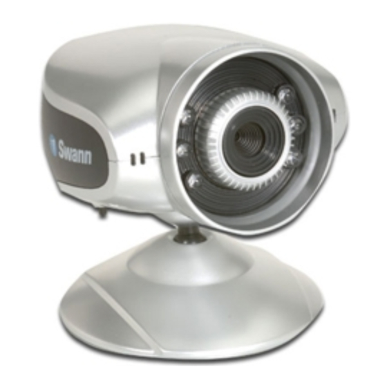
2.2 MAX-IP-CAM EXTERNAL FUNCTION INTRODUCTION IR LED x 6 Microphone Status Light Reset Switch Reset Switch button operation: When in operation, press and hold the Reset Switch button for 3 seconds and the system will re-boot. If you press and hold down the SW button for longer than 5 seconds, the system will return to factory default settings. -
Page 8: Tv_Out Function Introduction
2.3 TV_OUT FUNCTION INTRODUCTION Reset Switch Using the following method, you can display the images from the Max-IP-Cam on your TV The Default Video signal setting for TV_OUT is NTSC system, please press and hold the Reset switch for 3 seconds to change to PAL system. -
Page 9: Getting Started
(please refer to settings step 3.2.1 ). Otherwise, the system will display the following warning, and be unable to display the surveillance feeds. After having successfully set up the Max-IP-Cam settings during the first use, users do not need to change the settings again for later use. - Page 10 3.2.1 The IE security settings can be changed by following the steps below: Step 1. IE Toolbar ---> Tools ---> Internet Options ---> Security ---> Custom Level¡K Step 2. After clicking on Custom Level, a security settings window shall appear; Change ActiveX Control Options and Plug-ins settings to the following: 1.
-
Page 11: Take A Shot
ActiveX content from the Internet without authorization, you will be prompted to allow the ActiveX component of your browser to interact with the MAX-IP-Cam each time you access it. When you view the stream from the MAX-IP-Cam and you see the prompts regarding downloading, running or enabling ActiveX content from the IP address of the MAX-IP-Cam, click "Yes"... -
Page 12: Advanced Function With Liveview
4. ADVANCED FUNCTION WITH LIVEVIEW Move the cursor to the live image, and right click with your mouse. A small menu should appear with four options. - Image: Adjust image values - Record: Setup for recording into AVI format - Zoom: Select digital zoom value for window - Motion Detec Set: Settings for motion detection... -
Page 13: Motion Detection Setup
The image will zoom in according to the dimensions entered and will show an image similar to this below. 4.4 MOTION DETECTION SETUP Setting up the Motion Detection (MD) values, including the first area (red border) and second area (green border). Please check to see whether the Event Trigger has been enabled. -
Page 14: Advanced Application
Internet connection hardware. Due to the many different models of Internet and Network connection hardware and varied methods of performing some of the required setting changes Swann can only provide limited support in the use and configuration of your Internet and Network hardware. -
Page 15: Capture View
5.2 CAPTURE VIEW This view includes: - Manual capture of still images using LiveView - Automatic capture of still images via MD How to Use Capture View: Step 1. Click on CaptureView to enter the menu. The menu is capable of saving up to 48 images, viewable on three pages of. -
Page 16: Network Setup
5.3.1 Event Event settings, including: - Motion Detection (set 1) - Motion Detection (set 2) Individual or both set signal input triggers can be selected. How to Use Event Settings: Step 1. Activate Event for either set (MD) will automatically display the trigger sensitivity) Step 2. - Page 17 This menu allows you to enter the IP address of the DNS (Domain Name Server). By doing this, you can replace the IP address of the Max-IP-Cam with an http name (such as myIPCam.XXX), making it easier to remember. The default DNS value is "168.95.1.1". If the...
-
Page 18: Server Setup
5.5 SERVER SETUP This menu allows you to enter various server settings, including: - 5.5.1...Mail Server - 5.5.3...DDNS Server - 5.5.2...FTP Server - 5.5.4...NTP Server 5.5.1 Mail Server This refers to settings pertaining to sending image files via a mail server. You must also make sure that the Mail Image settings from 5.3 EventTrigger are enabled to e-mail a file to the designated address upon event trigger. - Page 19 5.5.2 FTP Server This menu allows you to enter the FTP (File Transfer Protocol) Server settings. You must also make sure that the FTP Image settings from 5.3 EventTrigger are enabled to send a file to the designated FTP server via FTP upon event trigger. This system supports Port Mode and Passive Mode.
-
Page 20: Administration Setup
5.6 ADMINISTRATION SETUP This menu allows you to designate an IP Cam name, administrator password and other user passwords. Administrators may access all IP Cam functions and settings, while general users may only utilize the LiveView view and may not access any of the settings. 5.6.1 Camera Name This allows you to set an name for the Max IP Cam that will be displayed on the video for identification purposes. -
Page 21: Software Update
This menu allows you to update the IPCam software online. You may use this feature to update the internal Max-IP-Cam software in order to make sure you have the newest version available, as well as updates to fix any software glitches. -
Page 22: Appendix
(USING A HUB ) This section is intended to help users connect from a computer to the MAX-IP-Cam via a hub. It also describes how to connect to ADSL with a PPPoE type IP address and also how to connect to the MAX-IP-Cam using DDNS. - Page 23 Step 4: Enter the desired account name (the account name "Max_IP_Cam" is used in this example) and click to check the Acceptable Use Policy. Step 5: Enter your E-mail address and password application. Click on "Create Account" to complete the application;...
- Page 24 Step 8: Once you are logged in, click on the "Services" link then click on "Dynamic DNS" as shown below; Step 9: The "Dynamic DNS" menu should automatically appear. Click on "Add Dynamic DNS" as shown below; Step 10: Enter your Host Name (MaxIPCam has been used in this example for your reference) select the domain you wish to use, enter your current Internet IP address and click on "Add Host"...
- Page 25 DynDNS to ensure your camera can be viewed from an Internet address that does not change. See example below. B. Connecting to the MAX-IP-Cam with Your Home Computer (Using the Cam_EZ Search Tool) Step 1: Please connect the MAX-IP-Cam to the...
- Page 26 Step 6: In EZ Search Tool, click "Update" once more to search for the IPCam on the local network. Double click on "MAX-IP-Cam" from the list, and your browser will automatically take you to the MAX-IP-Cam login window. Please refer to Page 9 for information on how to browse the surveillance video from the MAX-IP-Cam.
- Page 27 Step 2: Go to the "Server" menu. Enter the host name, account ID and password in the appropriate field in "DDNS Server". Click on "Submit" to finish; Step 3: At this time, you must change the IP settings of your home computer back to their original values (automatically retrieve IP address).
- Page 28 Select "automatically retrieve IP Address [O]" and "Automatically retrieve DNS server address [B]". Click "OK". D. Using the MAX-IP-Cam EZ IPCam with DDNS Viewer. Step 1: Open Cam_EZ Search, and click "Update". Wait for about 60 seconds (actual time dependant on the quality of your connection).
-
Page 29: Appendix B. Faq
IP address of the individual devices on your network such as PC's, routers and the Max-IP-Cam. If your ISP has not assigned you a permanent or static IP address, the IP address of your Internet connection will change each time your Broadband modem logs in. -
Page 30: Glossary Of Terms Used In This Manual
GLOSSARY OF TERMS USED IN THIS MANUAL DDNS - Dynamic Domain Name System ~ A method of automatically linking back to your Dynamic IP address using an Internet address that does not change DHCP - Dynamic Host Configuration Protocol ~ A method use by Servers and Routers to assign dynamic IP addresses to your equipment each time you connect. -
Page 31: Helpdesk / Support Details
Swann. The repair or replacement will be warranted for either ninety (90) days or the remainder of the original one (1) year warranty period, whichever is longer. The end user is responsible for all freight charges incurred to send the product to Swann's repair centres.
Need help?
Do you have a question about the Max-IP-Cam and is the answer not in the manual?
Questions and answers