Table of Contents
Advertisement
Advertisement
Table of Contents

Summary of Contents for Origen ae S21T
- Page 1 Origen...
- Page 2 Revision S21T.V3/03.14 Copyright © 2014 Origen Technology. All rights reserved...
-
Page 3: Table Of Contents
S21T specifications S21T overview Opening the case Removing motherboard tray Micro ATX standoff installation VGA bracket/loop cable Optical disk drive installation Optical drive bezel installation Metal sticker fitting instructions Hard drive installation Hard drive configuration PCB/cable reference diagram TFT contols / menu operation... -
Page 4: S21T Specifications
External dimensions (WxHXD) 435 x 224 x 390mm Construction materials all aluminium chassis Motherboard support ATX, micro ATX, mini-ITX PSU support ATX PSU PCI card support full size Drive bays 10 x 3.5” internal drive bays 1 x 5.25” external drive bay Fan support 1 x 120mm low dB exhaust fan 2 x 92mm low dB intake fans... -
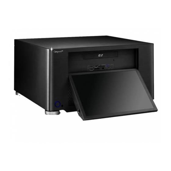
Page 5: S21T Overview
S21T overview S21T overview The following diagrams (below and overleaf) highlight the main features and controls of the S21T htpc enclosure. Further information can be found throughout this user guide. Power button Power LED ring TFT power ON/OFF button* IR receiver windows... - Page 6 S21T overview Hard drive (HD) stop-rail Optical disk drive (ODD) cage Motor assembly 92mm low dB fan HD mounting bracket ODD/HD support strut Extractor module mount One piece aluminum chassis Moulded back panel frame 10 - Removable motherboard tray...
-
Page 7: Opening The Case
Opening the case / removing the motherboard tray Opening the case To remove the lid of the case, undo the 2 thumb screws as indicated. Carefully lift the lid from the back but not too far - DO NOT FORCE, and then pull backwards. -
Page 8: Micro Atx Standoff Installation
Micro ATX standoff / VGA loop cable installation Micro ATX standoff installation When installing a micro ATX motherboard, screw the 2 standoffs provided in the locations illustrated above. These are for micro ATX only and MUST NOT be installed if using a full ATX motherboard. VGA loop cable This cable loops the VGA signal from the graphics card to the... -
Page 9: Optical Disk Drive Installation
Optical disc drive installation Optical disc drive (ODD) installation emove the ODD cage by undoing the 4 screws as illustrated below. Install ODD into the cage using the correct screws (supplied). Re-position the cage, with drive, and replace all screws to secure. Adjust (forward/back) position as necessary to ensure functionality of ODD eject button. -
Page 10: Optical Drive Bezel Installation
ODD bezel / metal sticker installation Optical disk drive (ODD) bezel installation. The aluminum ODD bezel matches the finish of the case. The installation procedure requires that the plastic drive bezel that comes fitted to your drive, be removed prior to installation. The drive format icon should also be fitted to the bezel before installation. -
Page 11: Hard Drive Installation
Hard drive installation Hard drive installation. o begin installation, remove the stop-rails as shown. You may need to loosen the screws first with a screwdriver. Drives must always be installed with the label facing toward the front of case. Screw three rubber mounting screws into the drive as shown below (the screw arrangement is mirrored for drives installed on the opposite side). -
Page 12: Hard Drive Configuration
Hard drive configuration Number of hard drives to be installed Hard drive configuration. In order to maximise airfow 9 10 and cooling of the hard drives, use the chart on the left to determine the optimum install configuration for the number of drives to be installed. -
Page 13: Pcb/Cable Reference Diagram
PCB/cable reference diagram PCB/cable reference diagram. This is a general overview illustrating how the S21T PCBs interconnect. PCBs / Cables dimmed in grey, come as part of an IR kit (sold separately). Please refer to your motherboard manual for the location of the correct ports and header pins. -
Page 14: Tft Contols / Menu Operation
TFT controls / menu operation 12.1 inch TFT aspect ratio resolution supports (261 x 163mm) 16 : 10 1280 x 800 1920 x 1080 TFT controls / menu operation Begin by pressing the (menu/set) button to bring up the on screen display (OSD). Use the buttons to navigate through the 10 menu categories. -
Page 15: Tft Menu Guide
TFT menu guide Brightness. V positions. follow the steps below to adjust brightness. follow the steps below to adjust V position. Contrast. Language (default is English). follow the steps below to change language. follow the steps below to adjust contrast. Phase. -
Page 16: Hidden Contols / Features
Hidden controls / features Hidden controls / features A few of the S21T’s controls and features have been discreetly located in order to retain the clean styling of the enclosure. These are as follows: TFT power on/off - Quick access button... -
Page 17: Card Reader & I/O Ports
Multi-format card reader & I/O ports Multi-format card reader & I/O ports The S21T comes fitted with a multi-format card reader as well as front audio, USB. The [internal] USB hub feeds the 2 front USB ports as well as the IR control and TFT touch panel, freeing up USB connectors on the motherboard. -
Page 18: Touch Panel Software Installation
Touch panel software installation Touch panel software installation. In order to use the touch panel, you must first install the TouchKit software from our website. To start the software installation, double click on the setup.exe file located in the TouchKit folder. After opening the setup.exe Ensure that ‘install PS/2 Sel ec t ‘None’... - Page 19 Touch panel software installation Change the Program Click ‘ Yes’ to per for m a The softwa re wi ll now scan Folder name if required and 4 poi nt cal ibr at ion. Th is is and install the touch screen click ‘Ne xt ’...
- Page 20 Origen Global HQ #209 Baesan B/D 763-2 Hengsin-Dong Dukyang- Gu Goyang City Gyounggi-Do 412-220 South Korea Website www.origen .com...
Need help?
Do you have a question about the S21T and is the answer not in the manual?
Questions and answers