Table of Contents
Advertisement
Quick Links
Advertisement
Chapters
Table of Contents

Related Manuals for Asus Z10PE-D8 WS


Summary of Contents for Asus Z10PE-D8 WS
- Page 1 Z10PE-D8 WS...
- Page 2 Product warranty or service will not be extended if: (1) the product is repaired, modified or altered, unless such repair, modification of alteration is authorized in writing by ASUS; or (2) the serial number of the product is defaced or missing.
-
Page 3: Table Of Contents
How this guide is organized ................x Where to find more information ............... x Conventions used in this guide ...............xi Typography .....................xi Z10PE-D8 WS specifications summary ..............xii Chapter 1: Product Introduction Welcome! ....................1-2 Package contents ..................1-2 Serial number label ..................1-3 Special features.................. -
Page 4: Contents
3.2.2 Using the dual function power switch .......... 3-3 Chapter 4: BIOS setup Managing and updating your BIOS ............4-2 4.1.1 ASUS CrashFree BIOS 3 utility........... 4-2 4.1.2 ASUS EZ Flash Utility ..............4-3 4.1.3 BUPDATER utility ............... 4-4 BIOS setup program .................. 4-6 4.2.1... - Page 5 Contents Advanced menu ..................4-13 4.5.1 ACPI Settings ................4-14 4.5.2 SMART Settings................ 4-14 4.5.3 NCT6779D Super IO Configuration .......... 4-15 4.5.4 Onboard LAN I210 Configuration ..........4-16 4.5.5 Serial Port Console Redirection ..........4-17 4.5.6 APM ..................4-20 4.5.7 Advance Power Management Configuration......
- Page 6 Contents Chapter 5: RAID Configuration Setting up RAID ..................5-2 5.1.1 RAID definitions ................5-2 5.1.2 Installing hard disk drives ............5-3 5.1.3 Setting the RAID item in BIOS ............ 5-3 5.1.4 RAID configuration utilities ............5-3 LSI Software RAID Configuration Utility ..........5-4 5.2.1 Creating a RAID set ..............
- Page 7 Software drivers and utilities installation ..........6-13 Running the Support DVD ..............6-13 Installing the drivers and utilities ............6-16 6.4.1 Using the ASUS InstAll application ........... 6-16 6.4.2 Installing a driver or utility............6-18 Running the utilities ................. 6-20 6.5.1...
-
Page 8: Notices
Radio Interference Regulations of the Canadian Department of Communications. This class B digital apparatus complies with Canadian ICES-003. REACH Complying with the REACH (Registration, Evaluation, Authorization, and Restriction of Chemicals) regulatory framework, we publish the chemical substances in our products at ASUS REACH website at http://csr.asus.com/english/REACH.htm. viii... -
Page 9: Safety Information
Safety information Electrical safety • To prevent electrical shock hazard, disconnect the power cable from the electrical outlet before relocating the system. • When adding or removing devices to or from the system, ensure that the power cables for the devices are unplugged before the signal cables are connected. If possible, disconnect all power cables from the existing system before you add a device. -
Page 10: About This Guide
Where to find more information Refer to the following sources for additional information and for product and software updates. ASUS websites The ASUS website provides updated information on ASUS hardware and software products. Refer to the ASUS contact information. Optional documentation Your product package may include optional documentation, such as warranty flyers, that may have been added by your dealer. -
Page 11: Conventions Used In This Guide
Conventions used in this guide To make sure that you perform certain tasks properly, take note of the following symbols used throughout this manual. DANGER/WARNING: Information to prevent injury to yourself when trying to complete a task. CAUTION: Information to prevent damage to the components when trying to complete a task. -
Page 12: Z10Pe-D8 Ws Specifications Summary
DDR4 2133 / 1866 / 1600 MHz RDIMM/LR-DIMM/NVDIMM Quad channel memory architecture * Refer to www.asus.com for the memory QVL (Qualified Vendors Lists). Slot 1: 1 X PCIE x16 (x16 Gen3 Link) (near CPU socket) (Auto switch to x8 Link if slot 2 is occupied) - Page 13 ASUS Exclusive Features - Front Panel USB 3.0 Support Key Selling Points ASUS Quiet Thermal Solution - ASUS Fanless Design: Heat pipe solution ASUS EZ DIY - ASUS CrashFree BIOS 3 - ASUS EZ Flash 2 - ASUS MyLogo 2...
- Page 14 WfM 2.0, DMI 2.0, WOL by PME, WOR by PME, PXE Drivers ASUS Utilities Support DVD ASUS Update EEB Form Factor, 12 in. x 13 in. Form Factors * Refer to ASUS Server AVL for latest update. Specifications are subject to change without notice.
-
Page 15: Chapter 1: Product Introduction
Chapter 1: Product Introduction Product introduction This chapter describes the motherboard features and the new technologies it supports. -
Page 16: Welcome
Z10PE-D8 WS motherboard! The motherboard delivers a host of new features and latest technologies, making it another standout in the long line of ASUS quality motherboards! Before you start installing the motherboard, and hardware devices on it, check the items in your package with the list below. -
Page 17: Serial Number Label
Serial number label Before requesting support from the ASUS Technical Support team, you must take note of the motherboard's serial number containing 12 characters xxS1xxxxxxxx shown as the figure below. With the correct serial number of the product, ASUS Technical Support team members can then offer a quicker and satisfying solution to your problems. - Page 18 PCI Express 3.0 PCI Express 3.0 (PCIe 3.0) is the PCI Express bus standard that provides twice the performance and speed of PCIe 2.0. It provides optimal graphics performance, unprecedented data speed, and seamless transition with its complete backward compatibility to PCIe 2.0 devices.
-
Page 19: Innovative Asus Features
If a workstation is behaving abnormally, plug a flash drive into the adjacent USB port, press the motherboard's dedicated Flash log button and ASUS Q-Code event logs for the current live session wil be copied into the drive. ProCool Connector ProCool eliminates the hollow areas associated with traditional power connectors, ensuring and exceptionally close and secure connection with this motherboard. - Page 20 Chapter 1: Product introduction...
-
Page 21: Chapter 2: Hardware Information
Chapter 2: Hardware Information Hardware Information This chapter lists the hardware setup procedures that you have to perform when installing system components. It includes description of the jumpers and connectors on the motherboard. -
Page 22: Before You Proceed
Before you proceed Take note of the following precautions before you install motherboard components or change any motherboard settings. • Unplug the power cord from the wall socket before touching any component. • Use a grounded wrist strap or touch a safely grounded object or a metal object, such as the power supply case, before handling components to avoid damaging them due to static electricity. • Hold components by the edges to avoid touching the ICs on them. • Whenever you uninstall any component, place it on a grounded antistatic pad or in the bag that came with the component. • Before you install or remove any component, ensure that the power supply is switched off or the power cord is detached from the power supply. Failure to do so may cause severe damage to the motherboard, peripherals, and/or components. -
Page 23: Motherboard Overview
Place ten (10) screws into the holes indicated by circles to secure the motherboard to the chassis. DO NOT overtighten the screws! Doing so can damage the motherboard. Place this side towards the rear of the chassis ASUS Z10PE-D8 WS... -
Page 24: Z10Pe-D8 Ws Motherboard Layout
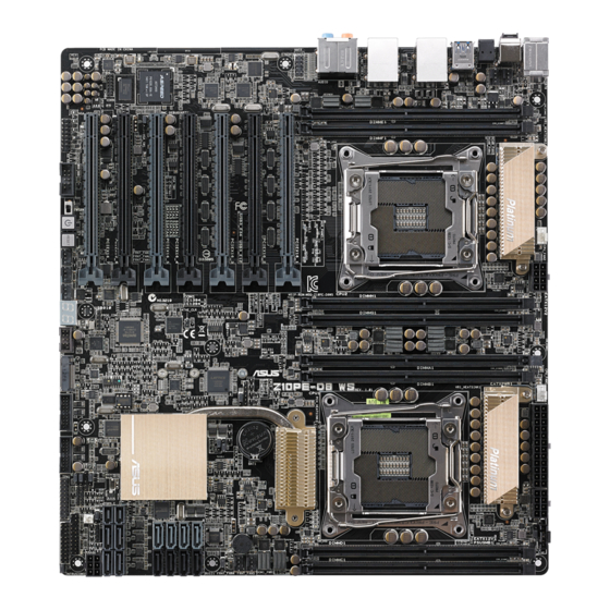
2.2.3 Z10PE-D8 WS Motherboard layout Chapter 2: Hardware information... -
Page 25: Layout Contents
4. CATT LED (CATTERR_LED1) 2-21 5. CPU Warning LED (ERR_CPU1, ERR_CPU2) 2-22 6. M2 LED (M2_LED) 2-22 7. ASUS Dr. Power LED (PGLED3) 2-23 8. Q-Code LED (LED1) 2-24 Jumpers Page 1. Clear RTC RAM (CLRTC1) 2-28 2. VGA controller setting (VGA_SW1) 2-29 3. SMBUS connection setting (TESLA_M_SW) 2-29 4. RAID selection jumper setting (3-pin RAID_SEL1) 2-30 5. ME firmware force recovery setting (3-pin ME_RCVR1) 2-30 6. DDR4 thermal event setting (3-pin DIMMTRIP1) 2-31 7. PMBus 1.2 PSU select jumper (3-pin SMART_PSU1) 2-31 ASUS Z10PE-D8 WS... - Page 26 Rear panel connectors Page 1. PS/2 mouse and keyboard port 2-32 2. Q-Code Logger button 2-32 3. Optical S/PDIF Out port 2-32 4. USB 3.0 ports 5 and 6 2-32 5. LAN 2 port 2-32 6. LAN 1 port (RJ-45 port for LAN1 and BMC share) 2-32 7. 8-channel Audio I/O 2-32 8. USB 2.0 ports 7 and 8 2-32 9. USB BIOS Flashback button 2-32 10. USB 3.0 ports 3 and 4 2-32 11. USB 3.0 ports 1 and 2 2-32 Internal connectors Page 1. Hard disk activity LED connector (4-pin HDLED1) 2-35 2. USB 2.0 connectors (10-1 pin USB910)
-
Page 27: Central Processing Unit (Cpu)
Central Processing Unit (CPU) ® The motherboard comes with a surface mount LGA 2011-3 socket designed for the Intel Xeon E5-2600 V3 family processor. • Upon purchase of the motherboard, ensure that the PnP cap is on the socket and the socket contacts are not bent. Contact your retailer immediately if the PnP cap is missing, or if you see any damage to the PnP cap/socket contacts/motherboard components. ASUS will shoulder the cost of repair only if the damage is shipment/ transit-related. • Keep the cap after installing the motherboard. ASUS will process Return Merchandise Authorization (RMA) requests only if the motherboard comes with the cap on the LGA 2011-3 socket. • The product warranty does not cover damage to the socket contacts resulting from incorrect CPU installation/removal, or misplacement/loss/incorrect removal of the PnP cap. 2.3.1 Installing the CPU To install a CPU: Locate the CPU socket on the motherboard. Before installing the CPU, ensure that the socket box is facing toward you and the triangle mark is on the top-right position. Triangle mark ASUS Z10PE-D8 WS... - Page 28 Press the left load lever down with your thumb (A), move it to the right until it is released from the retention tab (B) then gently lift the load lever (C). To prevent damage to the socket pins, do not remove the PnP cap unless you are installing a CPU. Load lever Press the right load lever with your thumb (D), move it to the left until it is released from then gently lift the load lever (F). Chapter 2: Hardware information...
- Page 29 Install the CPU into the slot. The CPU fits in only one correct orientation. DO NOT force the CPU into the socket to prevent bending the CPU pins on the socket. Gently push the load plate just enough to let it sit on top of the CPU. Do not force to close the load plate as it may damage the CPU. ASUS Z10PE-D8 WS...
- Page 30 10. Push down the right load lever (I) ensuring that the edge of the load plate is fixed and tucked securely under the lever (J) then insert the right load lever under the retention tab (K). The PnP cap pops out of the load plate when the right load lever is inserted into the retention tab. Keep the PnP cap. ASUS will process Return Merchandise Authorization (RMA) requests only if the motherboard comes with the PnP cap on the LGA 2011 socket. PnP cap 11. Push down the left load lever (L) then Retention tab insert it under the retention tab (M).
- Page 31 12. Apply some Thermal Interface Material to the exposed area of the CPU that the heatsink will be in contact with. • Ensure that the Thermal Interface Material is spread in an even thin layer. • Some heatsinks come with pre-applied Thermal Interface Material. If so, skip this step. The Thermal Interface Material is toxic and inedible. DO NOT eat it. If it gets into your eyes or touches your skin, wash it off immediately, and seek professional medical help. 13. Connect the CPU fan cable to the connector on the motherboard labeled CPU_FAN1 / CPU_FAN2. DO NOT forget to connect the CPU fan connector! Hardware monitoring errors can occur if you fail to plug this connector. ASUS Z10PE-D8 WS 2-11...
-
Page 32: System Memory
System memory 2.4.1 Overview The motherboard comes with eight (8) Double Data Rate 4 (DDR4) Dual Inline Memory Modules (DIMM) sockets. The figure illustrates the location of the DDR4 DIMM sockets: 2.4.2 Memory Configurations You may install 4 GB, 8 GB, 16 GB, and 32 GB RDIMMs or 32 GB and 64 GB LR-DIMMs into the DIMM sockets using the memory configurations in this section. • Refer to ASUS Server AVL for the updated list of compatible DIMMs. • When installing DIMMs, always start from slot A1 (CPU1) and E1 (CPU2). • Always install DIMMs with the same CAS latency. For optimum compatibility, it is recommended that you obtain memory modules from the same vendor. Chapter 2: Hardware information 2-12... - Page 33 Single CPU configuration You can refer to the following recommended memory population for a single CPU configuration. Single CPU configuration (must be installed on CPU1) DIMM 1 DIMM 2 DIMMs 4 DIMMs Dual CPU configuration You can refer to the following recommended memory population for a dual CPU configuration. Dual CPU configuration DIMM 2 DIMMs 4 DIMMs 8 DIMMs ASUS Z10PE-D8 WS 2-13...
-
Page 34: Installing A Dimm On A Single Clip Dimm Socket
2.4.3 Installing a DIMM on a single clip DIMM socket Press the retaining clip outward to DIMM notch unlock the DIMM socket. Align a DIMM on the socket such that the notch on the DIMM matches the DIMM slot key on the socket. DIMM slot key Unlocked retaining clip A DIMM is keyed with a notch so that it fits in only one direction. DO NOT force a DIMM into a socket in the wrong direction to avoid damaging the DIMM. Hold the DIMM at both ends then insert the DIMM into the socket. Apply force to both ends of the DIMM simultaneously until the retaining clip clicks into place and the DIMM is seated securely in place. -
Page 35: Expansion Slots
Secure the card to the chassis with the screw you removed earlier. Replace the system cover. 2.5.2 Configuring an expansion card After installing the expansion card, configure it by adjusting the software settings. Turn on the system and change the necessary BIOS settings, if any. See Chapter 4 for information on BIOS setup. Assign an IRQ to the card. Refer to the table Standard Interrupt assignments in section Interrupt assignments for more information. Install the software drivers for the expansion card. When using PCI cards on shared slots, ensure that the drivers support “Share IRQ” or that the cards do not need IRQ assignments. Otherwise, conflicts may arise between the two PCI groups, making the system unstable and the card inoperable. ASUS Z10PE-D8 WS 2-15... -
Page 36: Interrupt Assignments
2.5.3 Interrupt assignments Standard Interrupt assignments Priority Standard function System Timer Keyboard Controller Programmable Interrupt Communications Port (COM2) Communications Port (COM1) Floppy Disk Controller System CMOS/Real Time Clock ACPI Mode when used IRQ Holder for PCI Steering IRQ Holder for PCI Steering PS/2 Compatible Mouse Port Numeric Data Processor Primary IDE Channel Secondary IDE Channel * These IRQs are usually available for ISA or PCI devices. 2.5.4 PCI Express x16 slot (x16 link) The onboard PCIE 1 and 3 provide one x16 Gen3 link to CPU1 (Auto switch to x8 link if PCIE 2 and 4 are occupied); The onboard PCIE 5 and 7 provide one x16 Gen3 link to CPU2. These slots support VGA cards and various server class high performance add-on cards. -
Page 37: Motherboard Layout
Motherboard Layout 1 x PCIE x16 (x16 Gen3 Link) PCIE 1 (Near CPU socket. Auto switch to x8 Link if slot 2 is occupied) 1 x PCIE X16 (x8 Gen3 Link) PCIE 2 1 x PCIE x16 (x16 Gen3 Link) PCIE 3 (Auto switch to x8 Link if slot 4 is occupied) 1 x PCIE X16 (x8 Gen3 Link) PCIE 4 1 x PCIE x16 (x16 Gen3 Link) PCIE 5 1 x PCIE x16 (x8 Gen3 Link) PCIE 6 1x PCIE x16 (x16 Gen3 Link) PCIE 7 ASUS Z10PE-D8 WS 2-17... -
Page 38: Onboard Buttons And Switches
Onboard buttons and switches Onboard switches allow you to fine-tune performance when working on a bare or open- case system. This is ideal for overclockers and gamers who continually change settings to enhance system performance. Power-on The motherboard comes with a power-on switch that allows you to power up or wake up the system. The switch also lights up when the system is plugged to a power source indicating that you should shut down the system and unplug the power cable before removing or plugging in any motherboard component. -
Page 39: Dr. Power Switch (Dr_Power)
Dr. Power switch (DR_POWER) Toggle this switch to enable or disable the Dr. Power feature of the system. ASUS Z10PE-D8 WS 2-19... -
Page 40: Onboard Leds
Onboard LEDs Memory Error LED (ERR_DIMMA1, ERR_DIMMB1, ERR_DIMMC1, ERR_DIMMD1, ERR_DIMME1, ERR_DIMMF1, ERR_DIMMG1, ERR_DIMMH1) These LEDs light up to indicate an error in its nearby DIMM. Baseboard Management Controller LED (BMC_LED1) The BMC LED works with the ASUS ASMB8 management device and indicates its initiation status. When the PSU is plugged and the system is OFF, ASUS ASMB8 management device starts system initiation for about one (1) minute. The BMC LED blinks after system initiation finishes. Chapter 2: Hardware information 2-20... -
Page 41: Location Led (Locled2)
Location LED (LOCLED2) This onboard LED lights up when the Location button on the server is pressed or when triggered by a system management software. The Location LED helps visually locate and quickly identify the server in error on a server rack. CATT LED (CATTERR_LED1) The CATT LED indicates that the system has experienced a fatal or catastrophic error and cannot continue to operate. ASUS Z10PE-D8 WS 2-21... -
Page 42: Cpu Warning Led (Err_Cpu1, Err_Cpu2)
CPU Warning LED (ERR_CPU1, ERR_CPU2) The CPU warning LEDs light up to indicate failure on either CPU1, CPU2, or both. This onboard LED lights up when the Location button on the server is pressed or when triggered by a system management software. The Location LED helps visually locate and quickly identify the server in error on a server rack. M2 LED (M2_LED) This LED lights up to indicate that the installed M.2 (NGFF) card is being accessed. Chapter 2: Hardware information 2-22... -
Page 43: Asus Dr. Power Led (Pgled3)
ASUS Dr. Power LED (PGLED3) This LED near the Dr. Power switch lights up when the Dr. Power switch is on Enable. ASUS Z10PE-D8 WS 2-23... -
Page 44: Q-Code Led (Led1)
Q-Code LED (LED1) The Q-Code LED design provides you the 2-digit display, allowing you to know the system status. Refer to the Q-code table below for details. Q-Code table Code Description Not used Power on. Reset type detection (soft/hard). AP initialization before microcode loading System Agent initialization before microcode loading PCH initialization before microcode loading Microcode loading AP initialization after microcode loading System Agent initialization after microcode loading PCH initialization after microcode loading Initialization after microcode loading Cache initialization 0C – 0D Reserved for future AMI SEC error codes Microcode not found Microcode not loaded PEI Core is started 11 – 14 Pre-memory CPU initialization is started Pre-memory System Agent initialization is started 15 – 18 Pre-memory PCH initialization is started 19 –... - Page 45 Video repost OS S3 wake vector call E4 – E7 Reserved for future AMI progress codes S3 Resume Failed S3 Resume PPI not Found S3 Resume Boot Script Error S3 OS Wake Error EC – EF Reserved for future AMI error codes Recovery condition triggered by firmware (Auto recovery) Recovery condition triggered by user (Forced recovery) Recovery process started Recovery firmware image is found Recovery firmware image is loaded F5 – F7 Reserved for future AMI progress codes Recovery PPI is not available Recovery capsule is not found Invalid recovery capsule FB – FF Reserved for future AMI error codes DXE Core is started NVRAM initialization Installation of the PCH Runtime Services ASUS Z10PE-D8 WS 2-25...
- Page 46 Q-Code table (continued) Code Description 63 – 67 CPU DXE initialization is started PCI host bridge initialization System Agent DXE initialization is started System Agent DXE SMM initialization is started System Agent DXE initialization (System Agent module specific) 6B – 6F PCH DXE initialization is started PCH DXE SMM initialization is started PCH devices initialization 73 – 77 PCH DXE Initialization (PCH module specific) ACPI module initialization CSM initialization 7A – 7F Reserved for future AMI DXE codes Boot Device Selection (BDS) phase is started Driver connecting is started PCI Bus initialization is started PCI Bus Hot Plug Controller Initialization PCI Bus Enumeration PCI Bus Request Resources PCI Bus Assign Resources Console Output devices connect Console input devices connect Super IO Initialization USB initialization is started...
-
Page 47: Acpi/Asl Checkpoints
No Console Input Devices are found Invalid password Error loading Boot Option (LoadImage returned error) Boot Option is failed (StartImage returned error) Flash update is failed Reset protocol is not available ACPI/ASL Checkpoints Code Description 0x01 System is entering S1 sleep state 0x02 System is entering S2 sleep state 0x03 System is entering S3 sleep state 0x04 System is entering S4 sleep state System is entering S5 sleep state 0x05 System is waking up from the S1 sleep state 0x10 System is waking up from the S2 sleep state 0x20 System is waking up from the S3 sleep state 0x30 0x40 System is waking up from the S4 sleep state 0xAC System has transitioned into ACPI mode. Interrupt controller is in PIC mode. 0xAA System has transitioned into ACPI mode. Interrupt controller is in APIC mode. ASUS Z10PE-D8 WS 2-27... -
Page 48: Jumpers
Jumpers Clear RTC RAM (CLRTC1) This jumper allows you to clear the Real Time Clock (RTC) RAM in CMOS. You can clear the CMOS memory of date, time, and system setup parameters by erasing the CMOS RTC RAM data. The onboard button cell battery powers the RAM data in CMOS, which include system setup information such as system passwords. To erase the RTC RAM: Turn OFF the computer and unplug the power cord. Move the jumper cap from pins 1–2 (default) to pins 2–3. Keep the cap on pins 2–3 for about 5–10 seconds, then move the cap back to pins 1–2. Plug the power cord and turn ON the computer. Hold down the <Del> key during the boot process and enter BIOS setup to re- enter data. Except when clearing the RTC RAM, never remove the cap on CLRTC jumper default position. Removing the cap will cause system boot failure! If the steps above do not help, remove the onboard battery and move the jumper again to clear the CMOS RTC RAM data. After the CMOS clearance, reinstall the battery. Chapter 2: Hardware information 2-28... -
Page 49: Vga Controller Setting (Vga_Sw1)
VGA controller setting (VGA_SW1) This jumper allows you to enable o disable the onboard VGA controller. Set to pins 1-2 to activate the VGA feature. SMBUS connection setting (TESLA_M_SW) This jumper allows you to select the connection to BMC or PHC for PCIE 1/3/5/7 SMBUS. ASUS Z10PE-D8 WS 2-29... -
Page 50: Raid Selection Jumper Setting (3-Pin Raid_Sel1)
RAID selection jumper setting (3-pin RAID_SEL1) This jumper allows you to select the PCH SATA RAID mode to use LSI MegaRAID software or Intel Rapid Storage Technology enterprise 3.0 RAID. Place the jumper ® caps over pins 1–2 if you want to use the LSI MegaRAID software RAID Utility (default); otherwise, place the jumper caps to pins 2–3 to use the Intel Rapid Storage Technology ® Enterprise Option ROM Utility. ME firmware force recovery setting (3-pin ME_RCVR1) This jumper allows you to force Intel Management Engine (ME) boot from recovery mode when ME become corrupted. -
Page 51: Ddr4 Thermal Event Setting (3-Pin Dimmtrip1)
DDR4 thermal event setting (3-pin DIMMTRIP1) This jumper allows you to enable or disable DDR4 DIMM thermal sensing event pin. PMBus 1.2 PSU select jumper (3-pin SMART_PSU1) This jumper allows you to select PSU PMBus version. Set to pins 1–2 for PMBus, set to pins 2–3 for others. ASUS Z10PE-D8 WS 2-31... -
Page 52: Connectors
Connectors 2.9.1 Rear panel connectors PS/2 mouse and keyboard port. This port is for a PS/2 mouse or keyboard. Q-Code Logger button. This button allows you to check Q-Code event logs. For more information, refer to the Using the Q-Code logger section of this user guide. Optical S/PDIF Out port. This port connects to Sony/Philips Digital Interconnect Format (S/PDIF) compliant devices or amplified speakers. USB 3.0 ports 5 and 6. These Universal Serial Bus (USB) ports are available for connecting USB 3.0 devices. LAN 2 port (RJ-45). This port allows Gigabit connection to a Local Area Network (LAN) through a network hub. Refer to the table below for the LAN port LED indications. - Page 53 Center/Subwoofer Black – Rear Speaker Out Rear Speaker Out Rear Speaker Out Gray – – Side Speaker Out* Side Speaker Out * For Windows 8.1 only ® ** For more information on the Audio I/o connections, see the Audio I/O connections section on the Appendice chapter. ASUS Z10PE-D8 WS 2-33...
-
Page 54: Q-Code Logger Button
To use the Q-Code logger: Insert the USB storage device to the dedicated Q-Code logger USB port. Press the Q-Code logger button for three seconds until the Flashback LED blinks three times, indicating that the Q-Code logger function is enabled. Q-Code logger port Q-Code logger button Using the USB Flashback USB BIOS Flashback allows you to easily update the BIOS without entering BIOS or operating system. To use USB Flashback: Download the latest BIOS file from the ASUS website. Extract and rename the BIOS image file to Z10PEWS.CAP. Copy Z10PEWS.CAP to the root directory of your USB storage device. Turn off the system and connect the USB storage device to the USB BIOS Flashback port. Press the USB BIOS Flashback button. A flashing light indicates that the BIOS Flashback function is enabled. The light goes out when the process of updating the BIOS is complete. USB BIOS Flashback port USB BIOS Flashback button Chapter 2: Hardware information 2-34... -
Page 55: Internal Connectors
2.9.2 Internal connectors Hard disk activity LED connector (4-pin HDLED1) This LED connector is for the storage add-on card cable connected to the SATA or SAS add-on card. The read or write activities of any device connected to the SATA or SAS add-on card causes the front panel LED to light up. USB 2.0 connectors (10-1 pin USB910) These connectors are for USB 2.0 ports. Connect the USB module cables to connectors USB78 and USB910, then install the modules to a slot opening at the back of the system chassis. These USB connectors comply with USB 2.0 specification that supports up to 480 Mbps connection speed. ASUS Z10PE-D8 WS 2-35... -
Page 56: Usb 3.0 Connector (20-1 Pin Usb3_34; Usb3_E12)
USB 3.0 connector (20-1 pin USB3_34; USB3_E12) This connector allows you to connect a USB 3.0 module for additional USB 3.0 front or rear panel ports. With an installed USB 3.0 module, you can enjoy all the benefits of USB 3.0 including faster data transfer speeds of up to 5Gbps, faster charging time for USB-chargeable devices, optimized power efficiency, and backward compatibility with USB 2.0. CPU, front and rear fan connectors (4-pin CPU_FAN1-2, FRNT_FAN1–5, REAR_FAN1-2) The fan connectors support cooling fans. Connect the fan cables to the fan connectors on the motherboard, ensuring that the black wire of each cable matches the ground pin of the connector. • DO NOT forget to connect the fan cables to the fan connectors. Insufficient air flow inside the system may damage the motherboard components. • These are not jumpers! DO NOT place jumper caps on the fan connectors! • All fans feature the ASUS Fan Speed Control technology. Chapter 2: Hardware information 2-36... -
Page 57: Power Supply Smbus Connector (Psusmb1)
Power supply SMBus connector (PSUSMB1) This connector supplies power for low-speed system management communications. Serial port connectors (10-1 pin COM1) These connectors are for the serial (COM) port. Connect the serial port module cable to one of these connectors, then install the module to a slot opening at the back of the system chassis. ASUS Z10PE-D8 WS 2-37... -
Page 58: Serial Ata 6.0/3.0 Gb/S Connectors (7-Pin Sata_1-4 [Gray])
Serial ATA 6.0/3.0 Gb/s connectors (7-pin SATA_1-4 [gray], SSATA_1-4 [black]) These connectors are for the Serial ATA signal cables for Serial ATA hard disk drives that allows up to 6 Gbps of data transfer rate. If you installed Serial ATA hard disk drives, you can use a software RAID solution to create a RAID 0, RAID 1, RAID 5, or a RAID 10 configuration. For more information on the SATA RAID solutions supported on this motherboard, refer to the RAID Configuration chapter of this user guide. Chapter 2: Hardware information 2-38... -
Page 59: Sataexpress Connectors (7-Pin Sataexpress1 [Upper Port]; Sataexpress2 [Lower Port])
SATAEXPRESS connectors (7-pin SATAEXPRESS1 [upper port]; SATAEXPRESS2 [lower port]) These connectors connect to Serial ATA 6 Gb/s hard disk drives via Serial ATA 6 Gb/s signal cables. • ASMedia storage controller can only support AHCI mode. • These SATA ports are for data drives only. • The SATAEXPRESS1-2 connectors can support one SATA Express device or two SATA devices. Serial General Purpose Input/Output connector (6-1 pin SGPIO1, SSGPIO1) The SGPIO1 and SSGPIO1 connectors are used for the Intel Rapid Storage Technology Enterprise SGPIO interface that controls the LED pattern generation, device information, and general purpose data. SGPIO1 is the jumper for SATA1~4. SSGPIO1 is the jumper for SSATA1~4. ASUS Z10PE-D8 WS 2-39... -
Page 60: Ngff) Connector (Ngff1)
M.2 (NGFF) connector (NGFF1) This connector allows you to install an M.2 device. This connector supports type 2260 / 2280 / 22110 devices on both PCI-E and SATA interface. The M.2 (NGFF) device is purchased separately Trusted Platform Module connector (20-1 pin TPM1) This connector supports a Trusted Platform Module (TPM) system, which can securely store keys, digital certificates, passwords, and data. A TPM system also helps enhance network security, protects digital identities, and ensures platform integrity. Chapter 2: Hardware information 2-40... -
Page 61: Eatx Power Connectors (24-Pin Eatxpwr1; 8-Pin Eatx12V1/Eatx12V2; 6-Pin Eatx12V3)
EATX power connectors (24-pin EATXPWR1; 8-pin EATX12V1/EATX12V2; 6-pin EATX12V3) These connectors are for an EATX power supply plugs. The power supply plugs are designed to fit these connectors in only one orientation. Find the proper orientation and push down firmly until the connectors completely fit. • DO NOT forget to connect the 24+8+8-pin power plugs; otherwise, the system will not boot up. • We recommend that you connect the 6-pin EATX 12V3 power cable when installing more than two GPU or video graphics card. • Use of a PSU with a higher power output is recommended when configuring a system with more power-consuming devices. The system may become unstable or may not boot up if the power is inadequate. • This motherboard supports EATX2.0 PSU or later version. • Ensure that your power supply unit (PSU) can provide at least the minimum power required by your system. ASUS Z10PE-D8 WS 2-41... -
Page 62: Chassis Intrusion (2-Pin Intrusion1)
Chassis Intrusion (2-pin INTRUSION1) These leads are for the intrusion detection feature for chassis with intrusion sensor or microswitch. When you remove any chassis component, the sensor triggers and sends a high level signal to these leads to record a chassis intrusion event. The default setting is short CHASSIS# and GND pin by jumper cap to disable the function. Chapter 2: Hardware information 2-42... -
Page 63: System Panel Connector (20-1 Pin Panel1)
BIOS settings. Pressing the power switch for more than four seconds while the system is ON turns the system OFF. (6) Reset button (2-pin RESET) This 2-pin connector is for the chassis-mounted reset button for system reboot without turning off the system power. ASUS Z10PE-D8 WS 2-43... -
Page 64: Auxiliary Panel Connector (20-2 Pin Aux_Panel1)
Auxiliary panel connector (20-2 pin AUX_PANEL1) This connector is for additional front panel features including front panel SMB, locator LED and switch, and LAN LEDs. (1) Front panel SMB (6-1 pin FPSMB) These leads connect the front panel SMBus cable. (2) LAN activity LED (2-pin LAN12_LED) These leads are for Gigabit LAN activity LEDs on the front panel. (3) Locator LED (2-pin LOCATORLED1 and 2-pin LOCATORLED2) These leads are for the locator LED1 and LED2 on the front panel. Connect the Locator LED cables to these 2-pin connector. The LEDs will light up when the Locator button is pressed. (4) Locator Button/Swich (2-pin LOCATORBTN) These leads are for the locator button on the front panel. This button queries the state of the system locator. -
Page 65: Digital Audio Connector (4-1 Pin Spdif_Out)
Digital audio connector (4-1 pin SPDIF_OUT) This connector is for an additional Sony/Philips Digital Interface (S/PDIF) port(s). Connect the S/PDIF Out module cable to this connector, then install the module to a slot opening at the back of the system chassis. The S/PDIF module is purchased separately. ASMB8 header (14-1 pin ASMB8) ® The ASMB8 connector on the motherboard supports an ASUS Server Management Board 8 Series. ASUS Z10PE-D8 WS 2-45... -
Page 66: Vga Connector (Vga_Hdr1)
VGA connector (VGA_HDR1) This connector supports the VGA High Dynamic-Range interface. Front panel audio connector (10-1 pin AAFP) This connector is for a chassis-mounted front panel audio I/O module that supports either HD Audio or legacy AC`97 audio standard. Connect one end of the front panel audio I/O module cable to this connector. • We recommend that you connect a high-definition front panel audio module to this connector to avail of the motherboard’s high-definition audio capability. • If you want to connect a high-definition front panel audio module to this connector, set the Front Panel Type item in the BIOS setup to [HD]; if you want to connect an AC'97 front panel audio module to this connector, set the item to [AC97]. By default, this connector is set to [HD]. Chapter 2: Hardware information 2-46... -
Page 67: Chapter 3: Powering Up
Chapter 3: Powering Up Powering Up This chapter describes the power up sequence, and ways of shutting down the system. -
Page 68: Starting Up For The First Time
Starting up for the first time After making all the connections, replace the system case cover. Be sure that all switches are off. Connect the power cord to the power connector at the back of the system chassis. Connect the power cord to a power outlet that is equipped with a surge protector. Turn on the devices in the following order: Monitor External storage devices (starting with the last device on the chain) -
Page 69: Powering Off The Computer
While the system is ON, press the power switch for less than four seconds to put the system to sleep mode or to soft-off mode, depending on the BIOS setting. Pressing the power switch for more than four seconds lets the system enter the soft-off mode regardless of the BIOS setting. ASUS Z10PE-D8 WS... - Page 70 Chapter 3: Powering up...
-
Page 71: Chapter 4: Bios Setup
Chapter 4: BIOS setup BIOS setup This chapter tells how to change the system settings through the BIOS Setup menus. Detailed descriptions of the BIOS parameters are also provided. -
Page 72: Managing And Updating Your Bios
BIOS in the future. Copy the original motherboard BIOS using the BUPDATER utility. 4.1.1 ASUS CrashFree BIOS 3 utility The ASUS CrashFree BIOS 3 is an auto recovery tool that allows you to restore the BIOS file when it fails or gets corrupted during the updating process. You can update a corrupted BIOS file using a USB flash drive that contains the updated BIOS file. -
Page 73: Asus Ez Flash Utility
4.1.2 ASUS EZ Flash Utility The ASUS EZ Flash Utility feature allows you to update the BIOS without having to use a DOS-based utility. Before you start using this utility, download the latest BIOS from the ASUS website at www.asus.com. To update the BIOS using EZ Flash Utility: Insert the USB flash disk that contains the latest BIOS file into the USB port. Enter the BIOS setup program. Go to the Tool menu then select ASUS EZ Flash Utility. -
Page 74: Bupdater Utility
The BUPDATER utility allows you to update the BIOS file in the DOS environment using a bootable USB flash disk drive with the updated BIOS file. Updating the BIOS file To update the BIOS file using the BUPDATER utility: Visit the ASUS website at www.asus.com and download the latest BIOS file for the motherboard. Save the BIOS file to a bootable USB flash disk drive. Copy the BUPDATER utility (BUPDATER.exe) from the ASUS support website at support.asus.com to the bootable USB flash disk drive you created earlier. Boot the system in DOS mode, then at the prompt, type: BUPDATER /i[filename].CAP where [filename] is the latest or the original BIOS file on the bootable USB flash disk drive, then press <Enter>. A:\>BUPDATER /i[file name].CAP Chapter 4: BIOS setup... - Page 75 The utility verifies the file, then starts updating the BIOS file. ASUS Tek. EzFlash Utility Current Platform New Platform Platform : Z10PE-D8 WS Platform : Z10PE-D8 WS Version : 0215 Version : 0217 Build date: 05/13/2014 Build date: 06/30/2014 Start Programming Flash. DO NOT SHUTDOWN THE SYSTEM!!! Write DO NOT shut down or reset the system while updating the BIOS to prevent system boot failure! The utility returns to the DOS prompt after the BIOS update process is completed.
-
Page 76: Bios Setup Program
If the system becomes unstable after changing any BIOS settings, load the default settings to ensure system compatibility and stability. Press <F5> and select Yes to load the BIOS default settings. • The BIOS setup screens shown in this section are for reference purposes only, and may not exactly match what you see on your screen. • Visit the ASUS website (www.asus.com) to download the latest BIOS file for this motherboard. Chapter 4: BIOS setup... -
Page 77: Bios Menu Screen
Event Logs For changing the event log settings Monitor F or displaying the system temperature, power status, and changing the fan settings Security For changing the security settings Boot For changing the system boot configuration Tool For configuring options for special functions Exit For selecting the exit options To select an item on the menu bar, press the right or left arrow key on the keyboard until the desired item is highlighted. Press the key on the upper right section of the menu screen to display the Tool and Exit menus. ASUS Z10PE-D8 WS... -
Page 78: Menu Items
4.2.3 Menu items The highlighted item on the menu bar displays the specific items for that menu. For example, selecting Main shows the Main menu items. The other items (Event Logs, Advanced, Monitor, Boot, Tool, and Exit) on the menu bar have their respective menu items. 4.2.4 Submenu items A solid triangle before each item on any menu screen means that the item has a submenu. To display the submenu, select the item then press <Enter>. 4.2.5 Navigation keys At the bottom right corner of a menu screen are the navigation keys for the BIOS setup program. Use the navigation keys to select items in the menu and change the settings. -
Page 79: Main Menu
Main menu When you enter the BIOS Setup program, the Main menu screen appears. The Main menu provides you an overview of the basic system information, and allows you to set the system date, time settings. 4.3.1 System Date [Day xx/xx/xxxx] Allows you to set the system date. 4.3.2 System Time [xx:xx:xx] Allows you to set the system time. ASUS Z10PE-D8 WS... -
Page 80: Aitweaker Menu
AiTweaker menu The AiTweaker menu allows you to perform overclocking and advance tuning of your memory and CPU settings. Ai Overclock Tuner [Auto] Allows you to optimize the CPU Core Ratio, BCLK Freqency, or memory paramaters. Configuration options: [Auto] [Manual] [OC Tune] Spread Spectrum [Auto] Allows you to enable or disable the spread spectrum. Configuration options: [Auto] [Enabled] [Disabled] Xeon Turbo Charger [Auto] Allows you to enable or disable Xeon Turbo Charger feature. Configuration options: [Auto] [Enabled] [Disabled] External Digi+ Power Control CPU1/CPU2 Load-line Calibration [Auto] Higher levels of the load-line calibration can get a higher voltage and a better... - Page 81 A higher temperature provides a wider CPU power thermal range and extends the overclocking tolerance to enlarge the overclocking potential. DRAM-AB/CD/EF/GH Current Capability [100%] The DRAM current capability adjusts the total power range for DRAM overclocking. A higher value provides a wider total power range and extends the overclocking frequency range simultaneously. Configuration options: [100%] [110%] [120%] [130%] [140%] DRAM-AB/CD/EF/GH Switching Frequency [Auto] The DRAM switching frequency will affect the overclocking range and the system stability. Configure a higher frequency to increase the overclockin range or a lower frequency to enhance the system stability. Configuration options: [Auto] [Manual] DRAM-AB/CD/EF/GH Power Phase Control [Auto] This is for the power supply ASUS Z10PE-D8 WS 4-11...
- Page 82 CPU1/2 Input Voltage [Auto] This is the input voltage for the processor by the external voltage regulator. DRAM Voltage (CHA, CHB)/(CHC, CHD)/(CHE, CHF)/(CHG, CHH) [Auto] Power supply for the DRAM. VCCIO Offset Mode Sign [ [+] VCCIO Voltage Offset by a positive value. [-] VCCIO Voltage Offset by a negative value. VCCIO Voltage Offset [Auto] Maximum offset vaue is 0.65 with an incement of 0.01V. Use +/- to raise or reduce the value.
-
Page 83: Advanced Menu
Front Panel Type [HD Audio] Allows you to select the Front Panel Type audio. Configuration options: [HD Audio] [AC97] Dr. Power Policy [Standard] Allows you select the policy of Dr. Power settings. Configuration options: [Standard] [Aggressive] ASUS Z10PE-D8 WS 4-13... -
Page 84: Acpi Settings
4.5.1 ACPI Settings Enable ACPI Auto Configuration [Disabled] Allows you to enable or disable the BIOS ACPI Auto Configuration. Configuration options: [Disabled] [Enabled] Enable Hibernation [Enabled] Allows you to enable or disable the ability of the system to hibernate (OS/Sleep State). Configuration options: [Disabled] [Enabled] This option may be not effective with some OS. ACPI Sleep State [S3 (Suspend to RAM)] This item allows you to select the highest ACPI sleep state the system will enter when the SUSPEND button is pressed. -
Page 85: Nct6779D Super Io Configuration
Allows you to set the parameters of Serial Port 1/ Serial Port 2. Serial Port [Enabled] Allows you to enable or disable Serial Port. Configuration options: [Disabled] [Enabled] Change Settings [Auto] Allows you to choose the setting for Super IO device. Configuration options: [Auto] [IO=3F8h; IRQ=4;] [IO=3F8h; IRQ=3, 4, 5, 6, 7, 9, 10, 11, 12;] [IO=2F8h; IRQ=3, 4, 5, 6, 7, 9, 10, 11, 12;] [IO=3E8h; IRQ=3, 4, 5, 6, 7, 9, 10, 11, 12;] [IO=2E8h; IRQ=3, 4, 5, 6, 7, 9, 10, 11, 12;] ASUS Z10PE-D8 WS 4-15... -
Page 86: Onboard Lan I210 Configuration
4.5.4 Onboard LAN I210 Configuration Intel Lan1/Lan2 Enable [Enabled] Allows you to enable or disable the Intel LAN. Configuration options: [Disabled] [Enabled] Intel LAN ROM Type [PXE] Allows you to select the Intel LAN ROM type. Configuration options: [PXE] [iSCSI] Chapter 4: BIOS setup 4-16... -
Page 87: Serial Port Console Redirection
The following item appears only when you set Console Redirection to [Enabled]. Console Redirection Settings This item becomes configurable only when you enable the Console Redirection item. The settings specify how the host computer and the remote computer (which the user is using) will exchange data. Both computers should have the same or compatible settings. ASUS Z10PE-D8 WS 4-17... - Page 88 Terminal Type [VT-UTF8] Allows you to set the terminal type. [VT100] ASCII char set. [VT100+] Extends VT100 to support color, function keys, et. [VT-UTF8] Uses UTF8 encoding to map Unicode chars onto 1 or more bytes [ANSI] Extended ASCII char set Bits per second [57600] Selects serial port transmission speed. The speed must be matched on the other side. Long or noisy lines may require lower speeds. Configuration options: [9600] [19200] [38400] [57600] [115200] Data Bits [8] Configuration options: [7] [8]...
-
Page 89: Console Redirection Settings
The following item appears only when you set Console Redirection to [Enabled]. Console Redirection Settings Out-of-Band Mgmt Port [COM1] Microsoft Windows Emergency Management Services (EMS) allow for remote management of a Windows Server OS through a serial port. Configuration options: [COM1] [COM2] Terminal Type [VT-UTF8] Microsoft Windows Emergency Management Services (EMS) allow for remote management of a Windows Server OS through a serial port. Configuration options: [VT100] [VT100+] [VT-UTF8] [ANSI] Bits per second [115200] Microsoft Windows Emergency Management Services (EMS) allow for remote management of a Windows Server OS through a serial port. Configuration options: [9600] [19200] [57600] [115200] Flow Control [None] Microsoft Windows Emergency Management Services (EMS) allow for remote management of a Windows Server OS through a serial port. Configuration options: [None] [Hardware RTS/CTS] [Software Xon/Xoff] ASUS Z10PE-D8 WS 4-19... -
Page 90: Apm
4.5.6 Allows you to configure the Advance Power Management (APM) settings. Restore AC Power Loss [Last State] When set to [Power Off], the system goes into off state after an AC power loss. When set to [Power On], the system will reboot after an AC power loss. When set to [Last State], the system goes into either off or on state, whatever the system state was before the AC power loss. Configuration options: [Power Off] [Power On] [Last State] Power On By PCIE [Disabled] [Disabled] Disables the PCIE devices to generate a wake event. [Enabled] Enables the PCIE devices to generate a wake event. Power On By Ring [Disabled] [Disabled] Disables the PCIE devices to generate a wake event. [Enabled] Enables the PCIE devices to generate a wake event. Power On By RTC [Disabled] [Disabled] Disables RTC to generate a wake event. [Enabled] When set to [Enabled], the items RTC Alarm Date (Days) and Hour/ Minute/Second will become user-configurable with set values. -
Page 91: Advance Power Management Configuration
Power Boost [Normal] Enabling this item allows you to increase extra power input to the procesors(s) and coumputing performance depenig on the applications. Ensure that your thermal solution and power supply are avble to handle this circunstance. Configuration Options: [Normal] [High] [Extreme] ASUS Z10PE-D8 WS 4-21... -
Page 92: Pci Subsystem Settings
4.5.8 PCI Subsystem Settings Allows you to configure PCI, PCI-X, and PCI Express Settings. Load RT32 Image [Enabled] Allows you to enable or disable RT32 Image Loading. Configuration options: [Disabled] [Enabled] Above 4G Decoding [Disabled] Allows you to enable or disable 64-bit capable devices to be decoded in above 4G address space. It only works if the system supports 64-bit PCI decoding. Configuration options: [Disabled] [Enabled] SR-IOV Support [Disabled] This option enables or disables SIngle Root IO Virtualization Support if the system has SR-... -
Page 93: Network Stack Configuration
Network stack [Enabled] Enables or disables the network stack feature. Configuration options: [Disable] [Enable] The following item appears only when Network stack is set to [Enabled]. Ipv4 PXE Support [Enabled] Enables or disables the Ipv4 PXE Boot Support. If disabled, Ipv4 PXE boot option will not be created. Configuration options: [Disabled] [Enabled]. Ipv6 PXE Support [Enabled] Enables or disables the Ipv6 PXE Boot Support. If disabled, Ipv6 PXE boot option will not be created. Configuration options: [Disabled] [Enabled]. PXE boot wait time [0] Wait time to press ESC key to abort the PXE boot. Media detect time [0] Wait time (in seconds) to detect media. ASUS Z10PE-D8 WS 4-23... -
Page 94: Csm Configuration
4.5.10 CSM Configuration CSM Support [Enabled] This option allows you to enable or disable CSM Support. Configuration options: [Disabled] [Enabled] GateA20 Active [Upon Request] This allows you to set the GA20 option. Configuration options: [Upon Request] [Always] Option ROM Messages [Force BIOS] This allows you to set the display mode for option ROM. Configuration options: [Force BIOS] [Keep Current] Boot Option filter [Legacy only] This option allows you to control the Legacy/UEFI ROMs priority. -
Page 95: Trusted Computing
4.5.11 Trusted Computing Configuration Security Device Support [Disabled] Allows you to enable or disable the BIOS support for security device. Configuration options: [Disabled] [Enabled] ASUS Z10PE-D8 WS 4-25... -
Page 96: Usb Configuration
4.5.12 USB Configuration Legacy USB Support [Enabled] Allows you to enable or disable Legacy USB device support. Configuration options: [Enabled] [Disabled] [Auto] XHCI Hand-off [Enabled] This is a workaround for 0Ses without XHCI hand-off support. The XHCI ownership change should be claimed by XHCI driver. Configuration options: [Disabled] [Enabled] EHCI Hand-off [Disabled] This is a workaround for 0Ses without EHCI hand-off support. The EHCI ownership change should be claimed by EHCI driver. Configuration options: [Disabled] [Enabled] USB Mass Storage Driver Support [Enabled] Allows you to enable or disable the USB Mass Storage drvier support. -
Page 97: Asmedia Storage Controller
This item allows you to enable or disable the ASMedia Storage Controller. Configuration options: [AHCI Mode] [IDE Mode] Hot Plug [Disabled] Allows you to enable or disable the hot-plug support. Configuration options: [Disabled] [Enabled] ASPM Support [Disabled] Allows you to enable the controller ASMP (active state power management) for energy saving support Configuration options: [Disabled] [Enabled] ASUS Z10PE-D8 WS 4-27... -
Page 98: Iscsi Configuration
4.5.14 iSCSI Configuration Allows you to configure the iSCSi parameters. Chapter 4: BIOS setup 4-28... -
Page 99: Intelrcsetup Menu
IntelRCSetup menu The IntelRCSetup menu items allow you to change the processor and chipset settings. ASUS Z10PE-D8 WS 4-29... -
Page 100: Processor Configuration
4.6.1 Processor Configuration Per Socket Configuration Allows you to set the number of cores to enable. 0 means all cores. Total of 14 cores available. Hyper Threading [Enabled] Allows you to enable or disable the Intel Hyper-Threading Technology function. When ® disabled, only one thread per activated core is enabled. Configuration options: [Disabled] [Enabled] Execute Disable Bit [Enabled] When disabled, forces the XD feature flag to always return 0. - Page 101 This Item allows you to enable or disable the extended APIC support. Configuration options: [Disabled] [Enabled] AES-NI [Enabled] This Item allows you to enable or disable the AES-NI support. Configuration options: [Disabled] [Enabled] Down Stream PECI [Disabled] This Item allows you to enable the PCIe Down Stream PECI writer. Configuration options: [Disabled] [Enabled] ASUS Z10PE-D8 WS 4-31...
-
Page 102: Advanced Power Management Configuration
4.6.2 Advanced Power Management Configuration Power Technology [Energy Efficient] This item allows you to enable power management features. Configuration options: [Disabled] [Energy Efficient] [Custom] Config TDP [Disabled] This item allows you to enable/disable the Config TDP. Configuration options: [Disabled] [Enabled] Config TDP Level [Disabled] This item appears only when Config TDG is set to [Enabled]. This allows you select the Config TDP level. Configuration options: [Disabled] [Enabled] CPU Advanced PM Turning This item allows you to set additional CPU Power Management settings. Energy Perf BIAS Energy Performance Tuning [Disabled] Allows your system to select from BIOS or operating system to choose enable energy... -
Page 103: Common Refcode Configuration
The HW switching mechanism disables the performance setting (0) when the total PO time is less than this threshold. PO TotalTimeThreshold High [58] The HW switching mechanism enables the performance setting (0) when the total PO time is greater than this threshold. 4.6.3 Common RefCode Configuration Numa [Enabled] This item enables or disables the Non uniform Memory Access (NUMA). Configuration options: [Disabled] [Enabled] ASUS Z10PE-D8 WS 4-33... -
Page 104: Qpi Configuration
4.6.4 QPI Configuration QPI General Configuration QPI Status This item displays information about the QPI status. Link Speed Mode [Fast] This item allows you to select the QPI link speed as either the fast mode or slow mode. Configuration options: [Slow] [Fast] Link Frequency Select [Auto] This item allows you for selecting the QPI link frequency Configuration options: [Auto] [6.4 GT/s] [8.0 GT/s] [9.6 GT/s] Link L0p Enable [Enable] Configuration options: [Disable] [Enable] Link L1 Enable [Enable] Configuration options: [Disable] [Enable] COD Enable [Auto] Configuration options: [Disabled] [Enabled] [Auto] Early Snoop [Auto] Configuration options: [Disabled] [Enabled] [Auto]... -
Page 105: Memory Configuration
Enhanced Log Parsing [Disabled] Allows you to enable or disable the Enhanced Log Parsing. Configuration options: [Auto] [Disabled] [Enabled] Data Scrambling [Auto] Allows you to enable/disable data scrambling. Configuration options: [Auto] [Disabled] [Enabled] Enable ADR [Disabled] Allows you to set the detecting and enabling of ADR. Configuration options: [Disabled] [Enabled] ASUS Z10PE-D8 WS 4-35... - Page 106 C/A Parity Enable [Auto] Allows you to enable or disable the DDR4's command address parity. Configuration options: [Auto] [Disabled] [Enabled] Memory Topology Displays memory topology with DIMM population information. Memory Thermal Allows you to configure thermal settings. Set Throttling Mode [Disabled] Configuration options: [Disabled] [OLTT] [CLTT] OLLT Peak BW% [xx] Allows you to set the peak allowed bandwidth for OLTT. This is in percentage and valid offset values is from 25-100. DIMM Temp Stat [xx] Allows you to select DIMMTEMPSTAT as temp_mid or tem_hi.
- Page 107 Memory Rank Sparing [Disabled] Allows you to enable or disable Memory Rank Sparing. Configuration options: [Disabled] [Enabled] Correctable Error Threshold [32767] Allows you to set the Correctable Error Threshold used for sparing, tagging, and leaky bucket. The range is from 1 to 32767. Patrol Scrub [Enabled] Allows you to enable or disable Patrol Scrub. Configuration options: [Disabled] [Enabled] Demand Scrub [Enabled] Allows you to enable or disable Demand Scrub. Configuration options: [Disabled] [Enabled] ASUS Z10PE-D8 WS 4-37...
-
Page 108: Iio Configuration
4.6.6 IIO Configuration EV DFX Features [Disabled] Set this option to allow DFX Lock Bits to remain clear. Configuration options: [Disabled] [Enabled] PCIE Slot Option ROM Configuration PCIE1-PCIE7 Option ROM [Enabled] Allows you to enable or disable the PCIE1-7 Option ROM. Configuration options: [Disabled] [Enabled] Intel VT for Directed I/O (VT-d) Intel VT for Directed I/O (VT-d) [Enabled] Allows you to enable or disable the Intel Virtualization Technology for Directed I/O. -
Page 109: Pch Configuration
4.6.7 PCH Configuration PCH Devices DeepSx Power Policies [Disabled] Allows you to configure the DeepSx Mode configuration. Configuration options: [Disabled] [Enabled in S5] [Enabled in S4 and S5] PCI Express Configuration PCH DMI ASPM [Enabled] Allows you to configure the PCH DMI ASPM. Configuration options: [Disabled] [Enabled] ASUS Z10PE-D8 WS 4-39... - Page 110 PCH sSATA Configuration sSATA Controller [Enabled] Allows you to enable or disable the sSATA Controller. Configuration options: [Disabled] [Enabled] Configure sSATA as [AHCI] Allows you to identify the SATA port is connected to Solid State Drive or Hard Disk Drive. Configuration options: [IDE] [AHCI] [RAID] Support Aggressive Link Power Management [Enabled] Allows you to enable or disable the Suport Aggressive Link Power (SALP) Management. Configuration options: [Disabled] [Enabled] Chapter 4: BIOS setup 4-40...
- Page 111 Allows you to identify the SATA port is connected to Solid State Drive or Hard Disk Drive. Configuration options: [IDE] [AHCI] [RAID] Support Aggressive Link Power Management [Enabled] Allows you to enable or disable the Suport Aggressive Link Power (SALP) Management. Configuration options: [Disabled] [Enabled] SATA Port 1-6 Port 1/ Port 2/ Port 3/ Port 4/ Port 5/ Port 6 [Enabled] Allows you to enable or disable the SATA port Configuration options: [Disabled] [Enabled] ASUS Z10PE-D8 WS 4-41...
- Page 112 USB Configuration xHCI Mode [Auto] Allows you to enable or disable the mode of operation of xHCI controller. Configuration options: [Auto] [Disabled] [Enabled] USB Ports Per-Port Disable Control [Disabled] Allows you to control each of the USB ports 1 to 8 disabling. Configuration options: [Disabled] [Enabled] The following items appears only when the USB Ports Per-Port Disable Control is set to [Enabled].
-
Page 113: Miscellaneous Configuration
PCH Thermal Device [Auto] Allows you to enable or disable the PCH Thermal Device (D31:F6). Configuration options: [Auto] [Disabled] [Enabled] Alert Enable Lock [Disabled] Allows you to lock all Alert Enable settings. Configuration options: [Disabled] [Enabled] 4.6.8 Miscellaneous Configuration Active Video [Offboard Device] Allows you to select the video type. Configuration options: [Onboard Device] [Offboard Device] ASUS Z10PE-D8 WS 4-43... -
Page 114: Server Me Configuration
4.6.9 Server ME Configuration Displays the Server ME Technology parameters on your system. 4.6.10 Runtime Error Logging Support Runtime Error Logging S/W Error Injection Support [Disabled] This item allows you to enable or disable the S/W Error Injection support. Configuration options: [Disabled] [Enabled] Whea Settings WHEA Support [Enabled] This item allows you to enable or disable the WHEA support. Configuration options: [Disabled] [Enabled] Memory Error Enabling : Memory corrected Error enabling [Disabled] This item allows you to enable or disable Memory corrected Errors. -
Page 115: Server Mgmt Menu
This item allows you to start a BIOS timer which can only be shut off by Intel Management Software after the OS loads. Configuration options: [Disabled] [Enabled] The following items is configurable only when the OS Watchdog Timer is set to [Enabled]. OS Wtd Timer Timeout [10 minutes] Allows you to configure the length fo the OS Boot Watchdog Timer. Configuration options: [5 minutes] [10 minutes] [15 minutes] [20 minutes] OS Wtd Timer Policy [Reset] This item allows you to configure the how the system should respond if the OS Boot Watch Timer expires. Configuration options: [Do Nothing] [Reset] [Power Down] Serial Mux [Disabled] This item allows you to enable or disable Serial Mux configuration. Configuration options: [Disabled] [Enabled] ASUS Z10PE-D8 WS 4-45... -
Page 116: System Event Log
System Event Log Allows you to change the SEL event log configuration. SEL Components [Enabled] Allows you to enable or disable all features of system Event Logging during boot. Configuration options: [Disabled] [Enabled] • The following items appears only when you set SEL Components to [Enabled]. • All values changed here do not take effect until computer is restarted. Erase SEL [No] Allows you to choose options for erasing SEL. Configuration options: [No] [Yes, On next reset] [Yes, On every reset] When SEL is Full [Do Nothing] Allows you to choose options for reactions to a full SEL. -
Page 117: Bmc Network Configuration
BMC network configuration The sub-items in this configuration allow you to configure the BMC network parameters. The items are blank if no BMC card is detected by the system. Config Address source [Unspecified] This item allows you to configure LAN channel parameters statistically or dynamically (by BIOS or BMC). Unspecified option will not modify any BMC network parameters during BIOS phase. Configuration options: [Unspecified] [Static] [DynamicBmcDhcp] View System Event Log This item allows you to view the system event log records. ASUS Z10PE-D8 WS 4-47... - Page 118 IPv6 BMC Network Configuration This item allows you to configure the parameter settings of IPv6 BMC network. IPv6 Display Full Field [Enable] Displays the full or brief IPv6 Field. Configuration options: [Disable] [Enable] IPv6 Display Full Formula [Enable] Displays the full or brief IPv6 Formula. Configuration options: [Disable] [Enable] IPv6 Display Letter Case [Upper Case] Displays the uppercase or lowercase letters of the alphabet. Configuration options: [Lower Case] [Upper Case] IPv6 BMC Lan IP Address Source [Unspecified] This item allows you to select and configure LAN channel parameters statically or...
-
Page 119: Event Logs Menu
Change this to enable or disable all features of Smbios Event Logging during boot. Configuration options: [Disabled] [Enabled] Erasing Settings Erase Event Log [No] Choose options for erasing Smbios Event Log. Erasing is done prior to any logging activation during reset. Configuration options: [No] [Yes, Next reset] [Yes, Every reset] When Log is Full [Do Nothing] Allows you to choose options for reactions to a full Smbios Event Log. Configuration options: [Do Nothing] [Erase Immediately] ASUS Z10PE-D8 WS 4-49... -
Page 120: View Smbios Event Log
Smbios Event Log Standard Settings Log System Boot Event [Disabled] Allows you to choose options to enable/disable logging of System boot event. Configuration options: [Enabled] [Disabled] 4.8.2 View Smbios Event Log Press <Enter> to view all smbios event logs. Chapter 4: BIOS setup 4-50... -
Page 121: Monitor Menu
The onboard hardware monitor automatically detects the voltage output through the onboard voltage regulators. CPU FAN1&2 FRNT FAN1 mode [Generic Speed] Allows you to configure the ASUS Smart Fan feature that smartly adjusts the fan speeds for more efficient system operation. Configuration options: [Generic Speed] [High Speed] [Full Speed] [Manual Mode] Duty % [50] This item appears only when CPU FAN1&2 FRNT FAN1 mode is set to [Manual Mode]. This item allows you to configure the fan duty setting from 10% to 100%. FRNT FAN2&3/4&5 mode; REAR FAN1&2 mode [Generic Speed] Allows you to configure the ASUS Smart Fan feature that smartly adjusts the fan speeds for more efficient system operation. Configuration options: [Generic Speed] [High Speed] [Full Speed] [Manual Mode] ASUS Z10PE-D8 WS 4-51... -
Page 122: Security Menu
4.10 Security menu This menu allows a new password to be created or a current password to be cchanged. The menu also enables or disables the Secure Boot state and lets the user configure the System Mode state. Administrator Password To set an administrator password: Select the Administrator Password item and press <Enter>. From the Create New Password box, key in a password, then press <Enter>. Confirm the password when prompted. To change an administrator password: Select the Administrator Password item and press <Enter>. -
Page 123: User Password
This item allows you to customize the Secure Boot settings. Secure Boot [Disabled] Secure Boot can be enabled if the system is running in User mode with enrolled platform Key (EPK) or if the CSM function is disabled. Configuration options: [Disabled] [Enabled] Secure Boot Mode [Custom] Allows you to set the Secure Boot selector. Configuration options: [Custom] [Standard] ASUS Z10PE-D8 WS 4-53... - Page 124 Key Management This item only appears when the item Secure Boot Mode is set to [Custom]. The Key Management item allows you to modify Secure Boot variables and set Key Management page. Default Key Provision [Disabled] Configuration options: [Disabled] [Enabled] Enroll All Factory Default Keys This item will ask you if you want to Install Factory Default secure keys. Select Yes if you want to load the default secure keys, otherwise select No. Save All Secure Boot Variables This item will ask you if you want to save all secure boot variables. Select Yes if you want to save all secure boot variables, otherwise select No. Platform Key (PK)/ Key Exchange Key (KEK)/ Authorized Signatures (DB)/ Authorized TimeStamps (DBT)/ Forbidden Signatures (DBX) Configuration options: [Delete] [Set New] [Append] Configuration options: [Set New] [Delete] [Append] Chapter 4: BIOS setup...
-
Page 125: Boot Menu
Configuration options: [Warning] [Halt] Boot Option Priorities These items specify the boot device priority sequence from the available devices. The number of device items that appears on the screen depends on the number of devices installed in the system. ASUS Z10PE-D8 WS 4-55... -
Page 126: Tool Menu
Tool menu The Tool menu items allow you to configure options for special functions. Select an item then press <Enter> to display the submenu. ASUS EZ Flash Allows you to run ASUS EZ Flash BIOS ROM Utility when you press <Enter>. Refer to the ASUS EZ Flash Utility section for details. Chapter 4: BIOS setup 4-56... -
Page 127: Exit Menu
Discard Changes & Reset Reset system setup without saving any changes. Save Options Save Changes Save changes done so far to any of the setup options. Discard Changes Discard changes done so far to any of the setup options. ASUS Z10PE-D8 WS 4-57... -
Page 128: Restore Defaults
Restore Defaults Restore/load default values for all the setup options. Save as User Defaults Save the changes done so far as User Defaults. Restore User Defaults Restore the User Defaults to all the setup options. Boot Override This items displays the available devices. The items that appears on the screen depends on the number of devices installed in the system. Click an item to start booting from the selected device. -
Page 129: Chapter 5: Raid Configuration
Chapter 5: RAID Configuration RAID Configuration This chapter provides instructions for setting up, creating, and configuring RAID sets using the available utilities. -
Page 130: Setting Up Raid
Setting up RAID The motherboard supports the following SATA RAID solutions: • LSI MegaRAID software RAID Configuration Utility with RAID 0, RAID 1, and RAID 10 support (for both Linux and Windows OS). ® • Rapid Storage Technology enterprise Option ROM Utility with RAID 0, RAID 1, Intel RAID 10, and RAID 5 support (for Windows OS only). -
Page 131: Installing Hard Disk Drives
Rapid Storage Technology if you installed Serial ATA ® hard disk drives on the Serial ATA connectors supported by the Intel C612 chipset. ® Refer to the succeeding section for details on how to use the RAID configuration utility. ASUS Z10PE-D8 WS... -
Page 132: Lsi Software Raid Configuration Utility
LSI Software RAID Configuration Utility The LSI MegaRAID software RAID configuration utility allows you to create RAID 0, RAID 1, or RAID 10 set(s) from SATA hard disk drives connected to the SATA connectors supported by the motherboard southbridge chip. To enter the LSI MegaRAID software RAID configuration utility: Turn on the system after installing all the SATA hard disk drives. -
Page 133: Creating A Raid Set
Configure View/Add Configuration Initialize Clear Configuration Objects Select Boot Drive Rebuild Check Consistency Defines Physical Arrays. An Array Will Automatically Become A VD Use Cursor Keys to Navigate Between Items And Press Enter To Select An Option ASUS Z10PE-D8 WS... - Page 134 The ARRAY SELECTION MENU displays the available drives connected to the SATA ports. Use the up/down arrow keys to select the drives you want to include in the RAID set, and then press <Space>. When selected, the drive indicator changes from READY to ONLIN A[X]-[Y], where X is the array number, and Y is the drive number.
- Page 135 RAID 0 READY Units= MB RAID 1 Size = 152146MB = OFF = On Accept SPAN = NO Choose RAID Level For This VD Use Cursor Keys To Navigate Between Items And Press Enter To Select An Option ASUS Z10PE-D8 WS...
- Page 136 Select Units from the Virtual Drive sub-menu, and then press <Enter>. Select the units for virtual drive size from the menu, and then press <Enter>. LSI Software RAID Configuration Utility Ver C.05 Sep 17,2010 BIOS Version A.10.09231523R Virtual Drive(s) Configured Easy Configuration - ARRAY SELECTION MENU RAID Size...
- Page 137 Initialize Select Boot Drive Objects Virtual Drive(s) Configured Rebuild Check Consistency RAID Size #Stripes StripSz Status 148.580GB 64KB ONLINE Select Yes Or No Use Cursor Keys To Navigate Between Items And Press Enter To Select An Option ASUS Z10PE-D8 WS...
- Page 138 Using New Configuration When a RAID set already exists, using the New Configuration command erases the existing RAID configuration data. If you do not want to delete the existing RAID set, use the View/Add Configuration command to view or create another RAID configuration. To create a RAID set using the New Configuration option From the Management Menu, select Configure >...
-
Page 139: Adding Or Viewing A Raid Configuration
The information of the selected hard disk drive displays at the bottom of the screen. Follow step 3 to 12 of section 5.2.1 Creating a RAID set: Using Easy Configuration to add a new RAID set. ASUS Z10PE-D8 WS 5-11... -
Page 140: Initializing The Virtual Drives
5.2.3 Initializing the virtual drives After creating the RAID set(s), you must initialize the virtual drives. You may initialize the virtual drives of a RAID set(s) using the Initialize or Objects command on the Management Menu. Using the Initialize command To initialize the virtual drive using the Initialize command From the Management Menu, select Initialize, and then press <Enter>. - Page 141 Size #Stripes StripSz Status Management Menu Configure Init of VD Is In Process 148.580GB 64KB ONLINE Initialize VD 0 Initialization Complete. Press Esc.. Objects Rebuild Check Consistency 100% Completed Virtual Drives Virtual Drive 0 SPACE-(De)Select, F10-Initialize ASUS Z10PE-D8 WS 5-13...
-
Page 142: Using The Objects Command
Using the Objects command To initialize the virtual drives using the Objects command From the Management Menu, select Objects > Virtual Drive, and then press <Enter>. LSI Software RAID Configuration Utility Ver C.05 Sep 17,2010 BIOS Version A.10.09231523R Objects Management Menu Adapter Configure Virtual Drive... - Page 143 Init Will Destroy Data On Selected VD(s) Use Cursor Keys To Navigate Between Items And Press Enter To Select An Option A progress bar appears on screen. If desired, press <Esc> to abort initialization. When initialization is completed, press <Esc>. ASUS Z10PE-D8 WS 5-15...
-
Page 144: Rebuilding Failed Drives
5.2.4 Rebuilding failed drives You can manually rebuild failed hard disk drives using the Rebuild command in the Management Menu. To rebuild a failed hard disk drive From the Management Menu, select Rebuild, and then press <Enter>. LSI Software RAID Configuration Utility Ver C.05 Sep 17,2010 BIOS Version A.10.09231523R Management Menu... - Page 145 FAIL A00-01 Rebuilding of Drive Will Take A Few Minutes. Start Rebuilding Drive (Y/N)? Check Consistency Port # 1 DISK 77247MB HDS72808PLA380 PF20A60A SPACE-(De)Select,F10-Start Rebuild,F2-Drive Information,F3-View Virtual Drives When rebuild is complete, press any key to continue. ASUS Z10PE-D8 WS 5-17...
-
Page 146: Checking The Drives For Data Consistency
5.2.5 Checking the drives for data consistency You can check and verify the accuracy of data redundancy in the selected virtual drive. The utility can automatically detect and/or detect and correct any differences in data redundancy depending on the selected option in the Objects > Adapter menu. The Check Consistency command is available only for virtual drives included in a RAID 1 or RAID 10 set. - Page 147 • Continue - Continues the consistency check. - Aborts the consistency check. When you restart checking, it • Abort continues from zero percent. When checking is complete, press any key to continue. ASUS Z10PE-D8 WS 5-19...
- Page 148 Using the Objects command To check data consistency using the Objects command From the Management Menu, select Objects, and then select Virtual Drive from the sub-menu. Use the arrow keys to select the virtual drive you want to check, and then press <Enter>.
-
Page 149: Deleting A Raid Configuration
Objects Select Boot Drive Rebuild Check Consistency Clear Existing Configuration Use Cursor Keys To Navigate Between Items And Press Enter To Select An Option The utility clears all the current array(s). Press any key to continue. ASUS Z10PE-D8 WS 5-21... -
Page 150: Selecting The Boot Drive From A Raid Set
5.2.7 Selecting the boot drive from a RAID set You must have created a new RAID configuration before you can select the boot drive from a RAID set. See section 5.2.1 Creating a RAID set: Using New Configuration for details. To select the boot drive from a RAID set From the Management Menu, select Configure >... -
Page 151: Enabling Writecache
Disk WC = On Check Consistency Read Ahead = On Disk Write Cache Setting of VD Use Cursor Keys To Navigate Between Items And Press Enter To Select An Option When finished, press any key to continue. ASUS Z10PE-D8 WS 5-23... -
Page 152: Intel ® Rapid Storage Technology Enterprise
® Intel Rapid Storage Technology enterprise SATA/SSATA Option ROM Utility The Intel Rapid Storage Technology enterprise SATA/SSATA Option ROM utility allows you ® to create RAID 0, RAID 1, RAID 10 (RAID 1+0), and RAID 5 set from Serial ATA hard disk drives that are connected to the Serial ATA connectors supported by the Southbridge. -
Page 153: Creating A Raid Set
]-Prev/Next [TAB]-(M)aster [SPACE]-(R)ecovery [ENTER]-Done Use the up/down arrow keys to move the selection bar then press <Space> to select a disk. A small triangle before the Port number marks the selected drive. Press <Enter> when you are done. ASUS Z10PE-D8 WS 5-25... - Page 154 Use the up/down arrow keys to select the stripe size for the RAID array (for RAID 0, 10 and 5 only) then press <Enter>. The available stripe size values range from 4 KB to 128 KB. The following are typical values: RAID 0: 128KB RAID 10: 64KB RAID 5: 64KB...
-
Page 155: Deleting A Raid Set
<N> to return to the DELETE VOLUME menu. DELETE VOLUME VERIFICATION ALL DATA IN THE VOLUME WILL BE LOST! (This does not apply to Recovery volumes) Are you sure you want to delete volume “Volume0”? (Y/N): ASUS Z10PE-D8 WS 5-27... -
Page 156: Resetting Disks To Non-Raid
5.3.3 Resetting disks to Non-RAID Take caution before you reset a RAID volume hard disk drive to non-RAID. Resetting a RAID volume hard disk drive deletes all internal RAID structure on the drive. To reset a RAID set: From the utility main menu, select 3. Reset Disks to Non-RAID and press <Enter>. Press the up/down arrow keys to select the drive(s) or disks of the RAID set you want to reset, then press <Space>. -
Page 157: Exiting The Intel Rapid Storage Technology Enterprise Sata/Ssata Option Rom Utility
Select the port of destination disk for rebuilding (ESC to exit): Port Drive Model Serial # Size XXXXXXXXXXX XXXXXXXX XXX.GB ]-Previous/Next [ENTER]-Select [ESC]-Exit Select a destination disk with the same size as the original hard disk. ASUS Z10PE-D8 WS 5-29... - Page 158 The utility immediately starts rebuilding after the disk is selected. When done, the status of the degraded RAID volume is changed to “Rebuild”. Intel(R) Rapid Storage Technology enterprise - SATA Option ROM - 3.6.0.1023 Copyright(C) 2003-12 Intel Corporation. All Rights Reserved. MAIN MENU 1.
-
Page 159: Setting The Boot Array In The Bios Setup Utility
Use up/down arrow keys to select the boot priority and press <Enter>. See the Boot menu section of Chapter 4 for more details. From the Exit menu, select Save Changes & Exit, then press <Enter>. When the confirmation window appears, select Yes, then press <Enter>. ASUS Z10PE-D8 WS 5-31... -
Page 160: Intel ® Rapid Storage Technology Enterprise (Windows)
® Intel Rapid Storage Technology enterprise (Windows) The Intel Rapid Storage Technology enterprise allows you to create RAID 0, RAID 1, RAID ® 10 (RAID 1+0), and RAID 5 set(s) from Serial ATA hard disk drives that are connected to the Serial ATA connectors supported by the Southbridge. -
Page 161: Creating A Raid Set
Click Next. • If you do not want to keep the data on one of the selected disks, select NO when prompted. • If you want to Enable volume write-back cache or Initialize volume, click Advanced. ASUS Z10PE-D8 WS 5-33... - Page 162 Confirm the volume creation, than click Create Volume to continue. This process could take a while depending on the number and size of the disks. You can continue using other applications during this time. Wait until the process is completed, then click OK when prompted. You still need to partition your new volume using Windows Disk Management before adding any data.
-
Page 163: Changing A Volume Type
RAID 0: 128KB RAID 10: 64KB RAID 5: 64KB We recommend a lower stripe size for server systems, and a higher stripe size for multimedia computer systems used mainly for audio and video editing. ASUS Z10PE-D8 WS 5-35... -
Page 164: Deleting A Volume
5.4.3 Deleting a volume Be cautious when deleting a volume. You will lose all data on the hard disk drives.Before you proceed, ensure that you back up all your important data from your hard drives. To delete a volume: From the utility main menu, select the volume (exp. Volume_0000) in Volumes field you want to delete. -
Page 165: Preferences
Allow you to set to show the notification area icon and show system information, warning, or errors here. E-Mail Preferences Allow you to set to sent e-mail of the following events: • Storage system information • Storage system warnings • Storage system errors ASUS Z10PE-D8 WS 5-37... - Page 166 Chapter 5: RAID configuration 5-38...
-
Page 167: Chapter 6: Driver Installation
Chapter 6: Driver installation Driver installation This chapter provides the instructions for installing the necessary drivers for different system components in both ® ® Linux and Windows Operating Systems. -
Page 168: Raid Driver Installation
RAID driver installation After creating the RAID sets for your server system, you are now ready to install an operating system to the independent hard disk drive or bootable array. This part provides the instructions on how to install the RAID controller drivers during OS installation. 6.1.1 Creating a RAID driver disk The system does not include a floppy drive. -
Page 169: Installing The Raid Controller Driver
Boot the computer using the Windows Server 2008 R2 OS installation disc. Follow the ® screen instructions to start installing Windows Server 2008 R2. When prompted to choose a type of installation, click Custom (advanced). Click Load Driver. ASUS Z10PE-D8 WS... - Page 170 A message appears, reminding you to insert the installation media containing the driver of the RAID controller driver. If you have only one optical drive installed in your system, eject the Windows OS installation disc and replace with the motherboard Support DVD into the optical drive.
- Page 171 Enterprise RAID driver disk to the USB floppy disk drive, select ® OK, then press <Enter>. Insert Driver Disk Insert your driver disk into /dev/fd0 and press “OK” to continue. Back The drivers for the RAID card are installed to the system. ASUS Z10PE-D8 WS...
- Page 172 When asked if you will load additional RAID controller drivers, select No, then press <Enter>. More Driver Disks? Do you wish to load any more driver disks? Follow the onscreen instructions to finish the OS installation. When the installation is completed, DO NOT click Reboot. Press <Ctrl> + <Alt> + <F2> to switch to the command-line interface from graphic user interface.
- Page 173 Boot the system from the Red Hat OS installation CD. Press <Tab> to edit options. While booting from DVD, press <ESC> to give the third party driver. Enter the following command at the boot: Linux dd blacklist=isci blacklist=ahci nodmraid, then press <ENTER>. ASUS Z10PE-D8 WS...
- Page 174 Select Yes using the <Tab> key when asked if you have the driver disk, then press <Enter>. Main Menu Do you have a driver disk? You have multiple devices which could serve as source for a driver disk. Choose one you like to use and select OK, then press <Enter>.
- Page 175 The drivers for the RAID card are installed to the system. When asked if you will load additional RAID controller drivers, select No, then press <Enter>. More Driver Disks? Do you wish to load any more driver disks? Follow the onscreen instructions to finish the OS installation. ASUS Z10PE-D8 WS...
- Page 176 Preparing the Linux Driver Ensure that there is another computer with a Linux-based OS to create the RAID driver. When creating the RAID driver, you may refer to the examples below which uses a 64bit SUSE Linux system to create a 64bit RAID driver for SUSE11 sp1. Copy the image file into the Linux system.
- Page 177 To install the LSI MegaRAID controller driver when installing SUSE Linux Enterprise Server OS: Boot the system from the SUSE OS installation CD. Use the arrow keys to select Installation from the Boot Options menu. Press <F6>, then select Yes from the menu. Press <Enter>. ASUS Z10PE-D8 WS 6-11...
- Page 178 Use the USB drive to provide the third-party driver during the OS installation. Type the command brokenmodules=ahci in Boot Options field, and press <Enter>. When below screen appears, select the USB floppy disk drive (sda) as the driver update medium. Select OK, then press <Enter>. Please choose the Driver Update medium.
-
Page 179: Software Drivers And Utilities Installation
The contents of the support DVD are subject to change at any time without notice. Visit the ASUS website (www.asus.com) for the latest updates on software and utilities. The support DVD is supported on Windows... -
Page 180: Utilities Menu
6.3.2 Utilities menu The Utilities menu displays the software applications and utilities that the motherboard supports. 6.3.3 Make Disk menu The MakeDisk menu contains items to create the Intel RAID driver disks. Press the arrow down button in the lower left part of the menu to view more items. 6-14 Chapter 6: Driver installation... - Page 181 Content may vary depending on motherboard model. 6.3.5 Contact information menu The Contact menu displays ASUS contact information, e-mail addresses, and useful links if you seek for more information or in need of technical support. ASUS Z10PE-D8 WS 6-15...
-
Page 182: Installing The Drivers And Utilities
DVD. 6.4.1 Using the ASUS InstAll application This sections describes how to install the drivers and utilities using ASUS InstAll, an ASUS exclusive installation wizard that allows you to conveniently install the drivers and utilities with just a few steps. - Page 183 Tick Install drivers and recommended tools automatically from InstAll (recommended) then click OK to open the main ASUS InstAll screen Tick Customize the installation of drivers or Install drivers only if you want to install selected drivers or utilies. When you select either of these two options, you need to specify the drivers or utilites you want to install.
-
Page 184: Installing A Driver Or Utility
Click OK to complete the installation. 6.4.2 Installing a driver or utility This section describes the steps on how to install a particular driver or utility from the support DVD. To install a driver or utility: Restart the computer, and then log on with Administrator privileges. Insert the motherboard/system support DVD into the optical drive. - Page 185 2. VGA card ASPEED AST2300 / AST2400 Display Driver ASMedia ASM1042 / ASM1142 USB 3.0 Host 3. USB Controllers Controller Driver 4. Audio Realtek High Definition Audio Driver Follow onscreen instructions to complete the installation. Restart the system. ASUS Z10PE-D8 WS 6-19...
-
Page 186: Running The Utilities
Running the utilities This section provides information about the utillities bundled with your motherboad. This section also includes detailed steps on how to launch and use the utiliites after installing them. 6.5.1 Ai Charger+ Ai Charger+ allows you to fast-charge your portable BC 1.1* and Apple mobile devices on your computer’s USB port faster than the standard USB devices**. -
Page 187: Usb Charger
The USB Charger+ does not support USB hubs and USB extension cables, and generic USB cables. • The USB Charger+ may not recognize some ASUS devices due to a special design. Launching USB Charger+ To launch USB Charger+, locate and double-click the USB Charger+ icon on your system. - Page 188 6-22 Chapter 6: Driver installation...
-
Page 189: Appendix A: Reference Information
Appendix A: Reference Information Reference Information This appendix includes additional information that you may refer to when configuring the motherboard. -
Page 190: Z10Pe-D8 Ws Block Diagram
Z10PE-D8 WS block diagram Appendix A: Reference information... -
Page 191: Audio I/O Connections
Audio I/O connections Connect to Headphone and Mic Connect to Stereo Speakers Connect to 2.1 channel Speakers Connect to 4.1 channel Speakers... - Page 192 Connect to 5.1 channel Speakers If you are using Windows 8.1 platform, use only the gray audio port for Side Speaker Out in a 6-channel configuration. Connect to 7.1 channel Speakers When the DTS UltraPC II function is enabled, ensure to connect the rear speaker to the gray port.
-
Page 193: Asus Contact Information
ASUS contact information ASUSTeK COMPUTER INC. Address 15 Li-Te Road, Peitou, Taipei, Taiwan 11259 Telephone +886-2-2894-3447 +886-2-2890-7798 E-mail info@asus.com.tw Web site http://www.asus.com Technical Support Telephone +86-21-38429911 +86-21-58668722 ext: 9101 Online Support http://support.asus.com/techserv/techserv.aspx ASUSTeK COMPUTER INC. (Taiwan) Address 15 Li-Te Road, Peitou, Taipei, Taiwan 11259... -
Page 194: Technical Support
+1-510-608-4555 Web site http://usa.asus.com Technical Support Support fax +1-812-284-0883 General support +1-812-282-2787 Online support http://support.asus.com/techserv/techserv.aspx ASUS COMPUTER GmbH (Germany and Austria) Address Harkort Str. 21-23, D-40880 Ratingen, Germany +49-2102-959911 Web site http://www.asus.de Online contact http://www.asus.de/sales Technical Support Telephone +49-1805-010923 Support Fax +49-2102-959911 Online support http://support.asus.com/techserv/techserv.aspx... - Page 195 Web site http://www.asus.com Technical Support Telephone +31-(0)591-5-70292 +31-(0)591-666853 E-mail advance.rma.eu@asus.com Online Support http://support.asus.com/techserv/techserv.aspx ASUS Polska Sp. z o.o. (Poland) Ul. Postępu 6, 02-676 Warszawa, Poland Address Web site http://pl.asus.com Technical Support Telephone +48-225718033 Online Support http://support.asus.com/techserv/techserv.aspx ASK-Service (Russia and CIS) Address г.Москва, ул.