Table of Contents
Advertisement
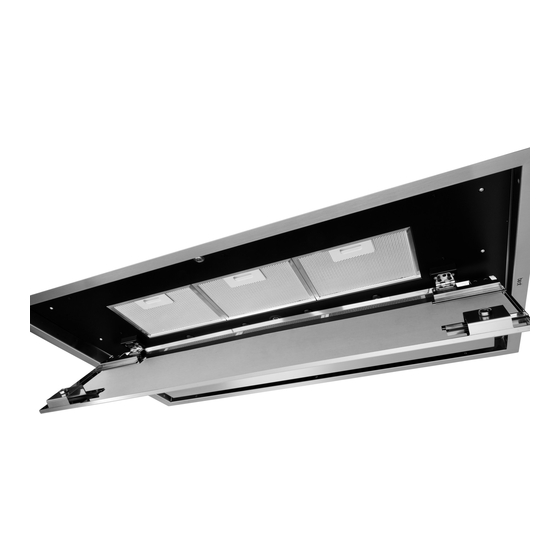
Model CC34
In USA - BEST Hartford, Wisconsin
In CANADA - BEST Drummondville, QC, Canada
REGISTER YOUR PRODUCT ONLINE AT : www.BestRangeHoods.com/register
For additional Information visit www.BestRangeHoods.com
ENGLISH.....................................2
FRANÇAIS.................................18
ESPAÑOL.................................. 34
I
QSB
Advertisement
Table of Contents

Related Manuals for Best CC34IQSB


Summary of Contents for Best CC34IQSB
- Page 1 Model CC34 ENGLISH........2 FRANÇAIS.........18 ESPAÑOL........34 In USA - BEST Hartford, Wisconsin In CANADA - BEST Drummondville, QC, Canada REGISTER YOUR PRODUCT ONLINE AT : www.BestRangeHoods.com/register For additional Information visit www.BestRangeHoods.com...
-
Page 2: To Reduce The Risk Of Fire, Electric Shock, Or Injury To Persons, Observe The Following
READ AND SAVE THESE INSTRUCTIONS INTENDED FOR DOMESTIC COOKING ONLY WARNING TO REDUCE THE RISK OF FIRE, ELECTRIC SHOCK, OR INJURY TO PERSONS, OBSERVE THE FOLLOWING: 1. Use this unit only in the manner intended by the manufacturer. If you have questions, contact the manufacturer at the address or telephone number listed in the warranty. -
Page 3: To Reduce The Risk Of A Range Top Grease Fire
The motor will restart when it cools down. If the motor continues to shut off and restart, have the hood serviced. For best capture of cooking impurities, the bottom of the hood should be a minimum of 48” and a maximum of 72” above the cooking surface. See “Install Mounting Bracket” section for mounting restrictions. -
Page 4: Operation
OPERATION Controls (Fig. 2) The hood is operated using the (5) push-buttons located on the hood and the remote control. LED colors are displayed on hood control only. P1: Activate/deactivate delay-off (10 minute) P2: Filter change indication timer reset ¤ P3: Decreases fan motor speed until turned off (4>3>2>1>OFF) P4: Turns fan motor on and increased speed (ON>1>2>3>4) P5: Turns lights on/off... -
Page 5: Remote Control
REMOTE CONTROL The remote control is linked to the hood at the factory. If, for some reason, the link is lost - follow the directions below: To Link Remote Control to Hood 1. Turn off hood motor and hood lights. 2. -
Page 6: Cleaning And Maintenance
CLEANING AND MAINTENANCE Proper maintenance of the Range Hood will assure proper performance of the unit. Motor The motor is permanently lubricated and never needs oiling. If the motor bearings make excessive or unusual noise, replace the motor with the exact service motor. The impeller should also be replaced. Grease Filters The grease filters should be cleaned frequently. -
Page 7: Prepare The Hood
PREPARE THE HOOD Unpack hood and check contents. You should receive: 1 - Range Hood Body 1 - Remote Control 6 - Grease Filters 2 - Screws, 4 x 9.5 mm 6 - Lag Bolts, 6 x 70 mm 6 - Washers 2 SCREWS (4 x 9.5 mm) 6 WASHERS... -
Page 8: Install The Ductwork
Use as few of them as possible. Larger ducting may be required for best performance with longer FIG. 6 duct runs. 4. Install a roof cap, wall cap, or under-eave vent. Connect round metal ductwork to cap/vent and work back towards hood location. - Page 9 2. The structure must be capable of support- ductwork. The hood should be mounted 48” ing its own weight, plus the weight of the to 72” above the cook top for best removal of hood (64 pounds). cooking impurities. Use joist size lumber to frame in around the 2 x 4 range hood opening.
- Page 10 ATTACH CONTROL BOX 1. Remove control box from side of blower box. Fig. 2. Insert control box into opening. Fig. 3. Attach control box with (2) 4 x 9.5 mm screws provided. Fig. CONTROL BOX TAPED TO BLOWER HOUSING FIG. 10 OPENING CONTROL IN HOOD...
-
Page 11: Install The Hood
INSTALL THE HOOD CAUTION: At least two installers are recommended because of the large size and weight of this range hood. 1. Hood is shipped in the horizontal duct discharge position and is ready to be installed. 2. To change direction of the duct without using elbows. - Page 12 3. From the room interior, pull down both closure panels. Fig. 4. Remove (4) screws from the electrical compartment access panel. Slide the panel sideways to expose the electrical wiring box. 5. From the electrical box marked “120 VAC Inlet” , remove (2) screws that secure the cover to the metal wiring box.
-
Page 13: Install The Filters
INSTALL THE FILTERS 1. Pull down both closure panels as shown. Fig. 19 and Fig. 2. To install the grease filters, align rear filter tabs with slots in the hood. Push latch tab in, push filter into position and release. Make sure filter is securely engaged after installation. -
Page 14: Service Parts
SERVICE PARTS Model CC34 KEY NO. DESCRIPTION PART NO. BLOWER ASSEMBLY 06002259 BLDC DRIVER 97019431 WIRES 06102601 WIRE CLAMP 03292290 BUSHING 03202288 ELECTRICAL INSTALLATION ASSEMBLY 06145222 WIRES 06102598 FEEDER CABLE CONNECTION BOX E3350233 BUSHING 03292596 FEEDER CABLE CONNECTION BOX COVER E3351530 UPPER TELESCOPIC SKELETON 08092797... - Page 15 SERVICE PARTS Model CC34 US-CIRRUS BLDC (03202288) (03292596) (03202288) (03202288) (06102601) (03202288) (03202288) (03202288) (06102598) ACR2 - 15 -...
-
Page 16: Warranty
Company’s most current written limited warranty for your particular product will control. The most current limited written warranties for the Company’s products can be found at www.BestRangeHoods.com. In USA - BEST Hartford, Wisconsin 800-558-1711 ®...
Need help?
Do you have a question about the CC34IQSB and is the answer not in the manual?
Questions and answers