Table of Contents
Advertisement
Quick Links
Advertisement
Chapters
Table of Contents

Related Manuals for KIP 3000


Summary of Contents for KIP 3000
- Page 1 K I P 3 0 0 0 U s e r G u i d e V e r s i o n C . 1...
- Page 2 Thank you for purchasing the KIP3000 Multi-Function Printer. This USER'S MANUAL contains functional and operational explanations for the KIP3000. Please read this USER'S MANUAL carefully before using the Printer. Please keep this USER'S MANUAL for future reference. 1. When this product is installed in North America. This device complies with part 15 of the FCC Rules.
-
Page 3: Safety Warnings
Safety Warnings The following warnings are very important in order to safely use this product. These notes are important in preventing danger to the operator or operation of the printer. The following symbols are found throughout the USER’S Manual and have the following meaning: WARNING This WARNING mark means that there is a possibility of death or serious injury if you ignore or do not follow the said instruction. - Page 4 WARNING Ground the product with a correct ground source or you may be electrically shocked. 1. The Power source should be as follows: In U.S.A. : 120V plus6% or minus10%, 50/60Hz, 15A or higher In Europe : 220-240V plus6% or minus10%, 50/60Hz, 10A or higher 2.
- Page 5 CAUTION Do not install the printer in a humidified room or a dusty room. Also, do not install the printer on an unstable floor as injuries may occur. 1. Unplug the printer before you move it. The power cord may be damaged and it may result in a fire or electric shock.
- Page 6 Section 5 Scan Mode – Color Section 6 Job Info Mode Section 7 Help – Configuration Section 8 Windows Drivers Section 9 AutoCAD Drivers Section 10 KIP Request Section 11 KIP PrintNet Section 12 Reporting Package - PRP Section 13 Connectivity...
-
Page 7: Table Of Contents
Section 1 Basic Printer Functions Before System Use 1- 1 1.1 Installation Requirements 1- 2 1.2 Prohibited Originals 1- 3 1.3 Key Features 1- 4 1.4 Specifications 1- 5 1.5 Exterior Views 1- 8 1.5.1 Front View 1- 8 1.5.2 Rear View 1- 9 1.5.3 Operator Panel 1- 10... - Page 8 1. 1 Installation Requirements The following conditions are required for the installation of the equipment. 1. Power source should be rated as: 120V +6% or -10%, 50/60Hz, 15A or higher 2. The equipment must be on a dedicated circuit. 3. The outlet must be near the equipment and easily accessible. 1.
-
Page 9: Prohibited Originals
1. 2 Prohibited Originals To duplicate or copy any type of document is not permitted! It may be illegal if you possess copies of certain types of documents. We recommend you investigate if you have the legal right to copy / scan a document prior to performing these functions. -
Page 10: Key Features
1. 3 Key Features The KIP 3000 is a single footprint Multi-Function Printer which can copy, scan and print. Advanced drivers and comprehensive print utilities make the KIP 3000 an advanced, easy to use system. (some functions may be optional) The scan and print speeds are up to 60mm/sec or up to 4 landscape “D”... -
Page 11: Specifications
1. 4 Specifications General Subject Specification Model KIP3000 Configuration Console Maximum power 1500W (Including Scanner & IPS) consumption Acoustic noise Idling Max. 52db Printing Max. 60db Impulse sound Max. 65db Ozone Max. 0.1ppm (Measurement method under UL Standard) Dimensions 1244mm (W) x 600mm (D) x 1100mm (H) or 50”... - Page 12 Printer Subject Specification Model KIP 3000 Configuration Console – Single Footprint Printing method LED Array Electro-Photography Photoreceptor Organic Photoconductive Drum Print speed 60mm per second (Metric) 2 A0 / minute (Inch) 2 E or 4 D Landscape / minute Print head LED Array –...
- Page 13 Scanner Subject Specification Scanning method Contact Image Sensor (CIS) (5 – A4) Light source Setting of original Face up Starting point of scan Center Scan width Max. : 914.4mm or 36” Min. : 275.0mm or 11” Transportable original Max. : 932.2mm or 36.7” width Min.
-
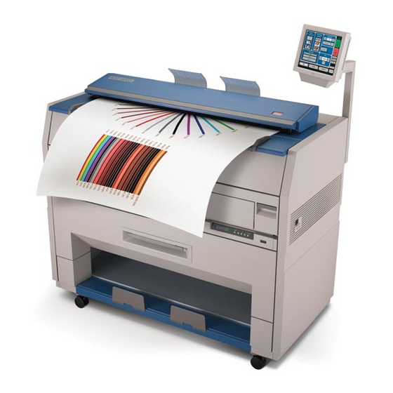
Page 14: Front View
Exterior Views 1. 5. 1 Front view Name Function Main Switch Turns on / off the KIP 3000. Original Guides Assists the user to feed originals into the scanner. User Interface Operation Panel, with many user operations. Emergency Stop Button Press this button when you would like to stop copying or scanning in an emergency situation. -
Page 15: Rear View
1. 5. 2 Rear view Name Function Exit Cover Open the Exit Cover when you remove the paper mis-fed inside of the Fuser Unit. LAN Port Connect the LAN Cable here to connect the KIP3000 to the network. (Do not connect a telephone line.) Note: There may also be a serial port in this area for folder connection ( optional device ) -
Page 16: Copy Mode
1. 5. 3 Operator Panel Copy Mode Name Function Mode Selects the “Mode” of the system. (Copy Mode for this screen shown) Media Displays Media type and quantity installed. Includes Cut Sheet Functions and Media Selection Original Type User Selects the type of original to copy. Also select Eng/Arch Modes here. -
Page 17: Scan Mode
Scan Mode Name Function Mode Selects the “Mode” of the system. (Scan Mode for this screen shown) Original Size Use automatic settings or manually set width, length and rotation of the images. Original Type User Selects the type of original to copy. Also select Eng/Arch Mode selected here. -
Page 18: Job Info Screen
Job Info Screen Name Function Mode Selects the “Mode” of the system. (Job Mode for this screen shown) User Name – Job # Display the User and any user info of the job ID. A job can be selected for other functions noted below. Media Information Displays Width, Type and amount remaining per roll deck Status... -
Page 19: Information / Help Screen
Meter – Versions Display the current meter counts as well as all Software/Firmware versions, IPS number, Host Name/IP (The area may vary depending on KIP printer model) KIP Contact Shows the contact information for the KIP Service and KIP Supplies provider. - Page 20 9) Dehumidifier Roll Deck Dehumidifier for locations with excess or high humidity All KIP 3000 options and accessories are subject to change without notice. Please contact your local Authorized Reseller for details on current available options for the KIP 3000.
-
Page 21: Turning On The Kip
1 minute. A Ready Indicator on the Copy Mode Screen will flash during the warm up process. Ready Indicator 4. When the Ready Indicator stops flashing, the KIP 3000 is ready to copy/scan/print. 1-15 Section 1 Basic Printer Functions... -
Page 22: Turning Off The Kip
Turning off the KIP 3000 1. There is a Power Switch on the right side of KIP3000. Switch to the “ O ” position to turn off the KIP 3000. Power Switch CAUTION The KIP3000 print engine and UI look to be shut down when you turn off KIP3000, the controller PC embedded inside of KIP3000 is still operating for shutdown in approximately two minutes after Power Switch operation. - Page 23 NOTE Please confirm that the machine has finished the printing completely before opening the Roll Deck. If you open the deck while its is still printing, a paper mis-feed will occur. 2. Press down the Lever (3) to release the paper core, and then pull out the Roll Spool (2) from the paper core.
- Page 24 4. Pressing down on the Lever (3), insert the Roll Spool (2) to the core of new roll paper. NOTE Be careful of the winding direction of the roll paper at this time. 5. Install the Roll Spool with new roll paper to the Roll Deck.
- Page 25 NOTE For Roll 2, rotate the Paper Feeding Knob on the rear side (10). 7. When the feeding rollers catch the paper, pull the middle of the Guide Plate 6 (11) out. Rotate the Paper Feeding Knob (9) again until the leading edge comes out in 8”. Leading edge of roll paper 8.
- Page 26 9. Rewind the roll paper to place the leading edge as the following photo. Place the leading edge here. 10. Close the Roll Deck (1). NOTE Be sure to close the Roll Deck fully until it is locked at the correct position. A paper jam may occur if it is not locked firmly.
-
Page 27: Toner Installation
2. 4 Toner Installation When toner installation is required, the Operator Panel will display a “Toner Required” screen (in the “Copy” and “Job Info” Screens) To replace the toner cartridge, please follow these steps: Please note that the replacement procedure can also be displayed on the Operator Panel for easier access, by pressing “User Guide : Changing Toner”... - Page 28 3. Pressing down the Cartridge Lock Lever (3), rotate the body (4) of cartridge to the arrow direction a few revolutions until it stops. You will “close” the toner supplying hole of the cartridge. NOTE The toner may drop from the toner supplying hole, and it may scattered into the machine or on the floor if you remove the Toner Cartridge without closing the toner supplying hole (5).
- Page 29 6. There is a pin (6) on the left side of cartridge, and there is a groove (7) on the machine side. Pressing down the Cartridge Lock Lever (3), fit the pin (6) to the groove (7). NOTE Please confirm that the Cartridge Lock Lever (3) firmly locks the Toner Cartridge at the correct position.
- Page 30 NOTE It is not necessary to lock the cartridge with the Lever (2). It rotates and locks the cartridge with closed the Toner Hatch. 8. Close the Toner Hatch (1). 9. Press “OK” on the Operator Panel to continue copying or printing. 1-24 Section 1 Basic Printer Functions...
-
Page 31: Cut Sheet Media Placement
2. 5 Cut Sheet Media Placement 1. Select Cut Sheet Bypass Button on the Operator Panel. (Copy Mode) 2. Select the size of the sheet, and the media type (not shown) 3. Or use “Custom” to select a width. 1-25 Section 1 Basic Printer Functions... - Page 32 4. Select a standard length or use a “Custom Length”. 5. Confirm the cut sheet size by pressing enter. 6. Open the Cut Sheet Feeder (1). 1-26 Section 1 Basic Printer Functions...
-
Page 33: Emergency Stop Of A Copy Or Scan
6. There are size markings on the table. Insert the cut sheet paper on the table along with the associated size mark, and then insert it into the Feeder referencing the size marks. When the paper is inserted far enough, the machine automatically sets the paper at the proper position. -
Page 34: Dehumidifying The Roll Media
2. 7 Dehumidifying the Roll Media If the roll paper is extremely humidified, it may cause several kinds of defective print. Defective prints you will experience most will be “crease of paper” and “loss of image”. Normal Print Crease of paper If the media is humidified ;... -
Page 35: Paper Mis-Feed Errors
3. 1 Operational Errors 3. 1. 1 Paper mis-feed errors Some message will be indicated on the LCD in case of a paper jam. Any of the following messages will be indicated. Feeding Jam Manual Jam Reg. Jam Internal Jam Fuser Jam Accessory Jam 3. - Page 36 2. Insert the leading edge of roll paper under the under the Guide Plate (1) until the edge touches the feeding roller. Then rotate the Paper Feeding Knob (2) clockwise so that the feeding rollers catch the roll paper. NOTE The leading edge should be trimmed with a cutter in case of an extreme crease.
- Page 37 4. Slide the Cutter Knob (5) fully from one side to another side to cut the leading edge. Remove the paper portion. NOTE Slide the Cutter Knob completely until it is stopped at the right or left end. If not there, a paper jam may occur. 5.
-
Page 38: Manual Jam
3. 1. 1. 2 Manual Jam 1. Pull up the Lever 2 (1) to open the Engine Unit. NOTE Do not open the Engine Unit when the Scanner Unit is opened. If the Scanner Unit is opened, it will hit the bottom of User Interface. 2. - Page 39 3. 1. 1. 3 Reg. Jam / Internal Jam 1. Pull up the Engine Unit Open Levers (1) to open the Engine Unit. NOTE Do not open the Engine Unit when the Scanner Unit is opened. If the Scanner Unit is opened, it will hit the bottom of User Interface. 2.
-
Page 40: Fuser Jam
3. 1. 1. 4 Fuser Jam 1. Pull up the Engine Unit Open Levers (1) to open the Engine Unit. NOTE Do not open the Engine Unit when the Scanner Unit is opened. If the Scanner Unit is opened, it will hit the bottom of User Interface. 2. -
Page 41: Accessory Jam
4. Open the Exit Cover (2). 5. Remove the jammed paper pulling to the rear side. WARNING There are extremely hot parts inside the Exit Cover. Do not touch any parts in the Heater Unit. or you will be burnt. Also be careful not to get burnt when you touch the printing paper as it may be very hot. -
Page 42: Original Jam
3. 1. 1. 6 Original Jam 1. Open the Scanner Unit pulling up the Levers (1), and then remove the original. 2. Move the Scanner Unit to the rear side slightly to unlock, and then close it. 1-36 Section 1 Basic Printer Functions... -
Page 43: Other
3. 1. 2 Others 3. 1. 2. 1 Deck open This message is indicated when the Roll Deck is opened. Close it firmly. Roll Deck 3. 1. 2. 2 Accessory Error Any error occurs in the optional device such as Auto Stacker or Folder. Clear the error making reference to the User’s Manual of concerning device. -
Page 44: Cutter Set
3. 1. 2. 4 Cutter Set This message is indicated when the Cutter Knob is not located at the correct position. Open the Roll Deck, and slide the Cutter Knob fully to the left or right to align the Cutter Knob with the end of the railing. - Page 45 3. 1. 2. 7 The door opened during the print This message is indicated when the Roll Deck is opened during printing by accident. Close the Roll Deck. If the paper is mis-fed inside the machine, remove it. Roll Deck 1-39 Section 1 Basic Printer Functions...
-
Page 46: Call Service Errors
3. 2 Call Service Errors In case the following Error Codes for a serious failure appear in the screen; PLEASE CALL YOUR TRAINED SERVICE PERSONNEL TO RESOLVE THE ERRORS. No operation should be done by the customer. Error Code Error Indication E - 000 Fuser Low Temp E - 001... -
Page 47: Scanner
4. 1 User Maintenance 4. 1. 1 Scanner Clean each Scan Glass, Feeding Rollers and Guide Plates once per a week, as the scan/copy image may become defective if these parts are dirty. 1. Turn off KIP3000. 2. Open the Scanner Unit pulling up the Levers (1). 2. - Page 48 3. Wipe both the Upper Guide Plate (4) and the Lower Guide Plate (5) with a soft dry cloth. 4. Move the Scanner Unit a little to the rear side to unlock, and then close it. 1-42 Section 1 Basic Printer Functions...
-
Page 49: Print Engine
4. 1. 2 Print Engine Clean each Guide Film and Guide Plate once per a week, as the toner or paper dust may accumulates on such part which may result in a defective print image. 1. Turn off KIP3000. 2. Open the Engine Unit pulling up the Engine Unit Open Levers (1). 2. - Page 50 NOTE (1) There is a Photoconductive Drum (large green cylinder) in the machine, which is right above the Guide Film. You will have to replace the Drum if it is damaged, as it is a very important part in creating the print image. Please take care of the following matters when you make cleaning.
-
Page 51: Touch Screen
4. 1. 3 Touch Screen Clean the Touch Screen once per a week. 1. Wipe the Touch Screen with a dry cloth. NOTE Do not use water, alcohol, organic solvent and glass cleaner for the cleaning. 1-45 Section 1 Basic Printer Functions... - Page 52 Section 2 Copy Mode - Monochrome 1. 0 Copy Mode - Monochrome..................... 2- 3 Main Screen - General ....................2- 3 Simple Copying ......................2- 4 1.2.1 Select Copy Mode ....................2- 4 1.2.2 Select Size Mode ..................... 2- 4 1.2.3 Select Original Image Type ..................
- Page 53 2.8.4 Auto Zoom........................ 2-27 2.8.5 Clear......................... 2-27 Start..........................2-27 2.10 View Last........................2-27 2.11 Recall Job ........................2-27 2.12 Stop / Reset ......................... 2-28 2.13 Interrupt........................2-28 2.14 Rescan ......................... 2-28 2.15 Log Off ......................... 2-28 Section 2 Copy Mode - Monochrome...
-
Page 54: Copy Mode - Monochrome
1. 0 Copy Mode - Monochrome 1.1 Main Screen - General Name Function Mode Selects the “Mode” of the system. (Copy Mode for this screen shown) Media Displays Media type and quantity installed. Includes Cut Sheet Functions and Media Selection Original Type User Selects the type of original to copy. -
Page 55: Simple Copying
1.2 Simple Copying To copy, please follow these basic steps. The following chapters have details on adjustments and parameters that the user can change to modify the copies as required. 1.2.1 Select Copy Mode On the lower region of the Operator Panel, select “COPY”. 1.2.2 Select Size Mode Select whether the document is an engineering or architectural size document. -
Page 56: Select Original Image Type
1.2.3 Select Original Image Type Set the original image type you will copy. The selections are: Line - used for simple line documents Line / Photo - used for a combination of lines & photos documents Grayscale - used for a combination of lines & areas of shade (CAD) originals Photo - used for photographic originals... -
Page 57: Media
1.2.5 Media Selects automatic (for best possible fit) or manual roll selection. 1.2.6 Length Select Auto for automatic cut length (to the length of the original) or Standard Cut for a manual length. (A number pad will request the desired length to be entered) Section 2 Copy Mode - Monochrome... -
Page 58: Size
Using the guides on the feed table, center the original face up and push forward until the KIP 3000 accepts it. The KIP 3000 will automatically commence to copy. While this occurs the image will be displayed on the Operator Panel for your reference. -
Page 59: Operation Details
This button is used to select the Size Mode of Engineering or Architectural. This will allow the automatic width detection system to determine the image width when an original is placed in the KIP 3000. Engineering widths = 34, 22, 17, 11, and 8.5 inches... -
Page 60: Original Type
2.2.2 Original Type Select one of the four different predetermined original types. The selections are: a) Line - used for simple line documents b) Line / Photo - used for a combination of lines & photos documents c) Grayscale - used for a combination of lines & areas of shade (CAD) originals d) Photo - used for photographic originals... -
Page 61: Threshold
2.3.2 Threshold To override the “Automatic” settings, “Threshold” can be adjusted. Deselect “Auto” to enable “Threshold”. Pressing the arrows manually adjusts the threshold. This will suppress or enhance the lines and images from the original. 2.3.3 Density To override the “Automatic” settings, “Density” can be adjusted. -
Page 62: Copy Count
2.4 Copy Count In this region the number of copies, and set copy / collation can be set. 2.4.1 Arrows - Count Increase / Decrease Use the arrows to increase or decrease the total numbers of copies desired by one with each press of the button. -
Page 63: Clear
c) Copying will not commence until the set is closed. To close a set, press the start button. The set with the total number of copies will be printed. Originals An example of Set Copy: 3 originals with 3 sets or copies Copies 2.4.4 Clear... -
Page 64: Advanced Settings
2.5 Advanced Settings The Advanced Setting button contains the additional parameters on a sub screen: a) Mirror b) Invert c) Fold (if optional device connected) d) Stamp (Water Mark) e) Lead Edge Adjustment f) Trail Edge Adjustment When any of the adjustments / selections is selected, the selections will now be displayed on the main Copy screen 2.5.1 Mirror... -
Page 65: Fold
They can not be altered or modified in any manner on the UI. Please contact these persons for any additional stamps that may be required. Please see “KIP Request” for these functions. An optional KIP Folder must be purchased to enable these functions. 2-14 Section 2... -
Page 66: Stamp
The list of “Stamps” is loaded into Copy Mode by the system administrator or key operator. They can not be altered or modified in any manner on the KIP printer’s Please contact these persons for any additional stamps that may be required. -
Page 67: Leading Edge Adjustment
2.5.5 Leading Edge Adjustment The leading edge of a copy can be altered. ( +/- 4” ) a) additional void area can be placed on the lead edge of a scan or b) image can be removed (such as a binding strip or a file hanger) Leading Edge + Leading Edge - Image... -
Page 68: Trailing Edge Adjustment
2.5.6 Trailing Edge Adjustment The trailing edge of each copy can be altered. ( +/- 4” ) c) Additional void area can be placed on the bottom of a copy or d) Image can be removed (such as a binding strip or a file hanger) Trail edge + Trail Edge - Image... -
Page 69: Auto
2.6.1 Auto This default setting allows the copier to automatically select the best media roll width to print the image onto. It selects the roll noting the amount of image area to prevent surplus media consumption. (applies to the option - two or more roll model) Example: 22”... -
Page 70: Enabling Cutsheet
2.6.3 Enabling Cutsheet Some KIP printers are equipped with a cut sheet feeder that can be enabled in the configuration menu of the UI. This can be accomplished by following these steps 1. Select the (?) button in the bottom left corner of the user interface. -
Page 71: Copying To Multiple Cutsheets
Select desired settings from the main copy screen. Feed your original (s) into the KIP 3000. Prepare Cut Sheet Feeder on your printer and WAIT until prompted by the UI. Insert the original into the Cut Sheet Feeder. Note: Only one cut sheet may be fed at a time and this function will time out after 3 minutes if no paper is inserted. -
Page 72: Installing Roll Media
Installing Roll Media When media is replaced or installed, a screen will automatically appear. This screen allows the setting of the media type and width. Please see the KIP Printer’s manual for the procedures to replace a roll of media. -
Page 73: Length
2.7 Length Two methods determine the length of the copy in the KIP printer. These two methods are Auto (may also be known as Synchro Cut or Automatic Cut) and Standard Cut. 2.7.1 Auto This mode allows the media length to be determined by the original length. - Page 74 If a roll is already selected in Media, then the following screen appears now only requesting the length. b) Once the roll is determined (if so required) the length can now be set. - Standard Length - Auto Length - Custom Length c) Standard Length –...
-
Page 75: Size - Zoom
e) Custom Length – set the custom length in the key pad and press enter f) The cut length will now be displayed in the main Copy screen in the Standard Cut button. 2.8 Size – Zoom Image size / Zoom can be altered in this region on the UI. This includes automatic zooming, predetermined percentages, or ratio calculations to page size, and simply percentage increments. -
Page 76: Preset Percentages
2.8.1 Preset Percentages The KIP printer has several predetermined industry standard zoom percentages used for quick access. These can be access with the arrow buttons. The pre-programmed percentages are: 50 - 66.7 - 70.7 - 100 - 141 - 150 - 200 2.8.2... -
Page 77: Page Size Zoom
2.8.3 Page Size Zoom To enter a zoom percentage based on pages sizes into the UI: Press on the Percentage value displayed (the number is a button). This will show a keypad to enter the value. Select Standard button. Select the original page size by pressing onto the original page size button. - Page 78 The copier is always set to “Auto Start”. That is when an originally is inserted into the KIP 3000, it will start without other user intervention. The start button is used when a job is recalled. The start button will “start”...
- Page 79 2.15 Log Off This button only appears when “Accounting” functions are enabled. This allows the current user to cease all KIP printer functions after the user has preformed the required copies. (after the code was entered to enable Coping)
- Page 80 Section 3 Copy Mode - Color Copy Mode – Color ......................3- 2 Main Screen - General ......................3- 2 Simple Copying ........................3- 3 1.2.1 Select Copy Mode......................3- 3 1.2.2 Select Size Mode ......................3- 3 1.2.3 Select Original Image Type....................3- 4 1.2.4 Print Quality........................3- 4 1.2.5 Copy Count ........................3- 5...
-
Page 81: Copy Mode - Color
1. 0 Copy Mode - Color 1.1 Main Screen - General Name Function Mode Select Color Mode from Mono Mode Original Size Select the size of the original in length and rotation Original Type User Selects the type of original to copy. Also select Eng/Arch Modes here. -
Page 82: Simple Copying
Please note that a third party color printer, supported by KIP, must first be calibrated in the “?” screen under the “Color Config” button. Please see the “?” Section. -
Page 83: Select Original Image Type
1.2.3 Select Original Image Type - Input Set the original image type you will copy. The selections are: Line - used for simple color line documents Line / Photo - used for a combination of lines & photos color documents Photo - used for color photographic originals This will allow automatic image quality adjustments for the scan. -
Page 84: Copy Count
1.2.5 Copy Count Press the arrow buttons to scroll through the number of copies required or press on the actual number to set the quantity with the number pad. 1.2.6 Original Size This selects automatic (for best possible fit) or manual page size selection. Section 3 Copy Mode –... -
Page 85: Size
Using the guides on the feed table, center the original face up and push forward until the KIP 3000 accepts it. The KIP 3000 will automatically commence to copy. While this occurs the image will be displayed on the Operator Panel for your reference. -
Page 86: Operation Details
This button is used to select the Size Mode of Engineering or Architectural. This will allow the automatic width detection system to determine the image width when an original is placed in the KIP 3000. Engineering widths = 34, 22, 17, 11, and 8.5 inches... -
Page 87: Original Type
2.2.2 Original Type - Input Select one of the three different predetermined original types. The selections are: a) Line - used for simple color line documents b) Line / Photo - used for a combination of color lines & photos c) Photo - used for color photographic originals Press the desired original setting from one of the three diagrams. -
Page 88: Copy Count
2.4 Copy Count In this region the number of copies, and set copy / collation can be set. 2.4.1 Arrows - Count Increase / Decrease Use the arrows to increase or decrease the total numbers of copies desired by one with each press of the button. -
Page 89: Set Copy
2.4.3 Set Copy Has no function in Color Copy Mode. 2.4.4 Clear Press the “eraser” button to reset the quantity to “1”. 2.5 Advanced Settings The Advanced Setting button contains the additional parameters on a sub screen: a) Mirror b) Invert c) Lead Edge Adjustment d) Trail Edge Adjustment When any of the adjustments / selections is selected, the... -
Page 90: Leading Edge Adjustment
2.5.3 Leading Edge Adjustment The leading edge of a copy can be altered. ( +/- 4” ) a) additional void area can be placed on the lead edge of a scan or b) image can be removed (such as a binding strip or a file hanger) Leading Edge Leading Edge - Image... -
Page 91: Trailing Edge Adjustment
2.5.4 Trailing Edge Adjustment The trailing edge of each copy can be altered. ( +/- 4” ) Additional void area can be placed on the bottom of a copy or Image can be removed (such as a binding strip or a file hanger) Trail Trail edge +... -
Page 92: Original Size
This region allows automatic or manual roll detection of the original. 2.6.1 Auto This default setting allows the KIP 3000 to automatically detect the width and length of the original. Please note the correct “Original Size Mode” in 2.2.1 must be select prior to the copy. -
Page 93: Custom
2.6.3 Custom This mode allows the original width and length to be determined by the number pad. a) Set the width of the scan. Note that these are only Standard Sizes. b) Set a Standard Length or Custom Length – set the Custom length in the key pad and press enter. -
Page 94: Rotation
Rotation available: 2.7 Size – Zoom Image size / Zoom can be altered in this region of the KIP operator panel. This includes automatic zooming, predetermined percentages, or ratio calculations to page size, and simple percentage increments. -
Page 95: Percentage Key Pad
2.7.2. Percentage Key Pad To enter a percentage directly: a) Press on the Percentage value displayed (the number is a button). b) This will show a keypad to enter the value (please note that the button Manual on the side is a default). c) Press the desired zoom value and press enter. -
Page 96: Clear
b) Select Standard button. c) Select the original page size by pressing onto the original page size button. d) Please note either Engineering or Architectural mode can be utilized by pressing on the button below the original page size. e) Select the desired Copy page size. Again please note either Engineering or Architectural mode can be utilized. -
Page 97: Start
KIP functions after the user has preformed the required copies (after the code was entered to enable Coping). Please note that the KIP printer will also automatically log off the current user after 180 seconds of no copy function activities by a user. 3-18 Section 3 Copy Mode –... - Page 98 Section 4 Scan Mode - Monochrome 1. 0 Scan Mode - Monochrome ..................... 4- 2 Main Screen ......................... 4- 2 Simple Scanning ......................4- 3 1.2.1 Select Scan Mode ....................4- 3 1.2.2 Select Size Mode ..................... 4- 3 1.2.3 Select Original Image Type ..................
-
Page 99: Scan Mode - Monochrome
Resets the system to default settings. Stops a scan in process Mailbox Select where the image will be stored after the scan (KIP printer, FTP, LAN PC etc). View Last View the last scanned image Rescan Rescans the last image (replaces) -
Page 100: Simple Scanning
1.2 Simple Scanning To scan to file, please follow these basic steps. The following chapters have details on adjustments and parameters that the user can change to modify the scans. 1.2.1 Select Scan Mode On the lower region of the UI, select “SCAN”. 1.2.2 Select Size Mode Select whether the document is an engineering or architectural size document. -
Page 101: Select Original Image Type
1.2.3 Select Original Image Type Set the Original Image type you will scan. The selections are: Line - used for simple line documents Line / Photo - used for a combination of lines & photos documents Grayscale - used for a combination of lines & areas of shade (CAD) originals Photo - used for photographic originals This will allow automatic image quality adjustments for the scan. -
Page 102: Select Format
1.2.4 Select Format Press the button to scroll through the file formats available. TIF-G4 - tif format Group 4 level compressed - KIP format compressed CAL-G4 - Cals Group 4 level - PDF Level 3 - Design Web Format (AutoCAD) -
Page 103: Select Mailbox
Using the guides on the feed table, center the original face up and push forward until the KIP 3000 accepts it. The KIP 3000 will automatically commence to scan. While this occurs the image will be displayed on the Operator Panel for your reference. -
Page 104: Operation Details
Image type. This will allow the automatic width detection system to determine the image width when an original is placed in the KIP 3000. (Eng) Engineering widths = 34, 22, 17, 11, and 8.5 inches (Arch) Architecture widths = 36, 30, 24, 18, 12, and 9 inches... -
Page 105: Original Type
This region is used to select the image size of the original being scanned. 2.3.1 Automatic Size For most scans, “Automatic” should be selected. This will allow the KIP 3000 to automatically determine the width and length of the scan without any user intervention. (Please also note “Original Size Mode” in 2.2) -
Page 106: Manual Size
2.3.2 Manual Size To select an original size manually, select Manual and a sub screen displays all current standard page sizes. Select a desired size of the sheet. Or use “Custom” to select a width. c) Set a standard size width. Section 4 Scan Mode - Monochrome... -
Page 107: Hard Drive Space Monitor
2.3.3 Hard Drive Space Monitor Located on the main screen of the KIP printer Scan mode, the Disk Use monitor provides a real-time display of remaining disk space on the KIP printer’s hard drive. The monitor shows both the used space and the space available for image storage on the drive. -
Page 108: Rotation
This region is used to change the image quality settings from the automatic setting. 2.4.1 Automatic For most scans, “Auto” should be selected. This will allow the KIP 3000 to automatically determine the best image settings without any user intervention. (Please also note “Original” in 2.2) 2.4.2 Threshold To override the “Automatic”... -
Page 109: Density
2.4.3 Density To override the “Automatic” settings, “Density” can be adjusted. Deselect “Auto” to enable “Density”. Pressing the arrows manually adjusts the background density. This will suppress or enhance the background from the original. 2.4.4 Sharpness To override the “Automatic” settings, “Sharpness” can be adjusted. Deselect “Auto”... -
Page 110: Format
2.6 Format Press the “Format” button to toggle through the file formats available. TIF-G4 - tif format Group 4 level compressed - KIP format compressed CAL-G4 - Cals Group 4 level - PDF Level 3 - Design Web Format (AutoCAD) -
Page 111: Advanced Settings
2.7 Advanced Settings The Advanced Setting button contains the additional parameters on a sub screen: a) Invert b) Mirror c) Stamp (Water Mark) d) Lead Edge Adjustment e) Trail Edge Adjustment Make any required adjustments / selections and press “OK” to accept. The selections will now be displayed on the main Scan screen. -
Page 112: Stamp
The list of “Stamps” is loaded into Scan Mode by the system administrator or key operator. They can not be altered or modified in any manner on the KIP printer’s Please contact these persons for any additional stamps that may be required. -
Page 113: Leading Edge Adjustment
2.7.4 Leading Edge Adjustment The leading edge of a scan can be altered. ( +/- 4” ) a) additional void area can be placed on the lead edge of a scan or b) image can be removed (such as a binding strip or a file hanger) Leading Edge + Leading Edge - Image... -
Page 114: Trailing Edge Adjustment
2.7.5 Trailing Edge Adjustment The trailing edge of a scan can be altered. ( +/- 4” ) c) additional void area can be placed on the bottom of a scan or d) image can be removed (such as a binding strip or a file hanger) Trail edge + Trail Edge - Image... -
Page 115: Mailbox
2.8 Mailbox This region of the Scan screen allows the user to select where the files will be placed. 2.8.1 Selecting a Mailbox a) Use the arrow keys to scroll through the list as needed. b) Select the location by pressing on it. 2.8.2 Removing a Mailbox a) Press the “-“... -
Page 116: Creating A New Mailbox
c) Press “Remove”. 2.8.3 Creating a New Mailbox a) Press the Mailbox Button. b) The Mailbox Setup screen is displayed. 4-19 Section 4 Scan Mode - Monochrome... -
Page 117: Smb Setup
Dsmith B_Project Team_XYZ Michele Access to these folders and the scanned images is preformed from the KIP Request application. Please see the User Guide of “KIP Request” for the retrieval function. FTP Locations Please contact your network administrator for details on how to configure and load FTP locations into the KIP printer Scan Mode. -
Page 118: Network Location (Smb/Cifs) - Ips Setup
[Mailbox Name]. c) Touch Destination Server/Workstation button to enter the NetBIOS name or IP address of the destination server or workstation that the KIP IPS will connect to in order to allow for scan to file. a. This must be a server or workstation that the KIP IPS has access to via TCP/IP. - Page 119 (Domain Controller/Active Directory Server) that will grant connection access to the KIP IPS for shared resources. If the KIP IPS is connecting to a workstation (WS01) that is a part of the Acme.com domain, then the user would enter Acme in the Domain section.
- Page 120 Username and Password should be set as an accessible login username from either the workgroup workstation/server or the authentication server/domain controller. g) Touching on Test SMB will make the KIP IPS attempt to establish a connection to the destination workstation/server.
-
Page 121: Ftp Site
In Request, enable Advance Features by selecting the Options menu and selection Advanced Features b) Click Options and then select Find KIP Printers and the Add a Printer to this List. Select Set FTP Address and enter the necessary FTP information... - Page 122 Send to the KIP IPS by using Transfer and then Upload Settings to Printer d) At the KIP IPS, enter (?) and then Service. Once you are in the Service menu, (password required) use the arrow keys at the bottom until “Import Settings” is shown (this will appear grayed out at first) touch the button labeled Touch.
-
Page 123: Start
2.9 Start No function at this time in Scan Mode. All scans in Scan Mode are “Auto Start”. 2.10 Reset / Stop This button has two functions. 1) Press the Stop button on the UI to stop the current scan. The original will be ejected automatically. - Page 124 Section 5 Scan Mode - Color 1. 0 Scan Mode – Color......................5- 2 Main Screen ......................... 5- 2 Simple Scanning ......................5- 3 1.2.1 Select Scan Mode ....................5- 3 1.2.2 Select Size Mode ..................... 5- 3 1.2.3 Select Original Image Type ..................5- 3 1.2.4 Select Format ......................
-
Page 125: Scan Mode - Color
Reset / Stop Resets the system to default settings. Stops a scan in process Mailbox Select where the image will be stored after the scan (KIP Mailbox, FTP, SMB) View Last View the last scanned image Rescan Rescans the last image (replaces) -
Page 126: Simple Scanning
1.2 Simple Scanning To scan to file in color, please follow these basic steps. The following chapters have details on adjustments and parameters that the user can change to modify color scans. 1.2.1 Select Scan Mode On the lower region of the UI, select “SCAN” then select Color Mode in the upper left corner. -
Page 127: Select Format
This will allow automatic image quality adjustments for the color scan. 1.2.4 Select Format Press the button to scroll through the file formats available. TIF Packbit JPEG PDF Color Select a desired file format. 1.2.5 Select Mailbox Select the location to where the file will be saved. -
Page 128: Insert Original
Using the guides on the feed table, center the original face up and push forward until the KIP 3000 accepts it. The KIP 3000 will automatically commence to scan. While this occurs the image will be displayed on the Operator Panel for your reference. -
Page 129: Operation Details
This button is used to select the Size Mode of Engineering or Architectural. This will allow the automatic width detection system to determine the image width when an original is placed in the KIP 3000. Engineering widths = 34, 22, 17, 11, and 8.5 inches Architectural widths = 36, 30, 24, 18, 12, and 9 inches 2.2.2... -
Page 130: Original Size
This region is used to select the image size of original being scanned. 2.3.1 Automatic Size For most scans, “Automatic” should be selected. This will allow the KIP 3000 to automatically determine the width and length of the scan without any user intervention. (Please also note “Original Size Mode” in 2.2.) 2.3.2... -
Page 131: Hard Drive Space Monitor
2.3.3 Hard Drive Space Monitor Located on the main screen of the KIP printer Scan mode, the Disk Use monitor provides a real-time display of remaining disk space on the KIP printer’s hard drive. The monitor shows both the used space and the space available for image storage on the drive. -
Page 132: Rotation
2.3.4 Rotation The file can be saved rotated from the actual feed direction. This can be used to reduce the scan time on certain orientation of originals, when they are archived. Press the “Rotation” button to select either one of four settings: 2.4 DPI Scroll through the DPI button to select the required scan resolution. -
Page 133: Advanced Settings
2.6 Advanced Settings The Advanced Setting button contains the additional parameters on a sub screen: a) Mirror b) Invert c) Lead Edge Adjustment d) Trail Edge Adjustment When any of the adjustments / selections is selected, the selections will now be displayed on the main Scan screen. -
Page 134: Trailing Edge Adjustment
To adjust the Leading Edge, use the arrows to denote the quantity you wish to add or remove. Touch the value displayed area to reset the quantity. 2.6.4 Trailing Edge Adjustment The trailing edge of each scan can be altered. ( +/- 4” ) c) additional void area can be placed on the bottom of a scan or d) image can be removed (such as a binding strip or a file hanger) Trail edge +... -
Page 135: Mailbox
2.7 Mailbox This region of the Scan screen allows the user to select where the color files will be placed. 2.7.1 Selecting a Mailbox a) Use the arrow keys to scroll through the list as needed. b) Select the location by pressing on it. 2.7.2 Removing a Mailbox a) Press the “-“... -
Page 136: Creating A New Mailbox
c) Press “Remove”. 2.7.3 Creating a New Mailbox a) Press the Mailbox Button. b) The Mailbox Setup screen is displayed. 5-13 Section 5 Scan Mode - Color... -
Page 137: Smb Setup
Dsmith B_Project Team_XYZ Michele Access to these folders and the scanned images is preformed from the KIP Request application. Please see the User Guide of “KIP Request” for the retrieval function. FTP Locations Please contact your network administrator for details on how to configure and load FTP locations into the KIP printer Scan Mode. -
Page 138: Network Location (Smb/Cifs) - Ips Setup
[Mailbox Name]. c) Touch Destination Server/Workstation button to enter the NetBIOS name or IP address of the destination server or workstation that the KIP IPS will connect to in order to allow for scan to file. a. This must be a server or workstation that the KIP IPS has access to via TCP/IP. - Page 139 (Domain Controller/Active Directory Server) that will grant connection access to the KIP IPS for shared resources. If the KIP IPS is connecting to a workstation (WS01) that is a part of the Acme.com domain, then the user would enter Acme in the Domain section.
- Page 140 Username and Password should be set as an accessible login username from either the workgroup workstation/server or the authentication server/domain controller. g) Touching on Test SMB will make the KIP IPS attempt to establish a connection to the destination workstation/server.
-
Page 141: Ftp Site
In Request, enable Advance Features by selecting the Options menu and selection Advanced Features b) Click Options and then select Find KIP Printers and the Add a Printer to this List. Select Set FTP Address and enter the necessary FTP information... - Page 142 Send to the KIP IPS by using Transfer and then Upload Settings to Printer d) At the KIP IPS, enter (?) and then Service. Once you are in the Service menu, (password required) use the arrow keys at the bottom until “Import Settings” is shown (this will appear grayed out at first) touch the button labeled Touch.
-
Page 143: Start
2.8 Start No function at this time in Scan Mode. All scans in Scan Mode are “Auto Start”. 2.9 Reset / Stop This button has two functions. 1) Press the Stop button to stop the current scan. The original will be ejected automatically. - Page 144 Section 6 Job Info Screen 1. 0 Job Info Screen 6- 2 1.1 Main Screen – Summary 6- 2 2. 0 Operation Details 6- 3 2.1 Job List - Main Screen 6- 3 2.2 User Name 6- 4 2.3 Job – Number 6- 4 2.4 Status 6- 5...
- Page 145 1. 0 Job Info Screen 1.1 Main Screen Name Function Mode Selects the “Mode” of the system. (Job Mode for this screen shown) User Name – Job # Display the User and any user info for the job ID. A job can be selected for other functions noted below.
- Page 146 2. 0 Operation Details The Job Info screen is used to view or manage the current copy or prints jobs on the KIP 5000. 2.1 Job List - Main Screen All jobs that are currently printing or are waiting to print are displayed in this area.
-
Page 147: User Name
Displays the “Name” or the “owner” of the job This information is obtained from fields within: a) KIP Request b) KIP Windows Driver c) KIP AutoCAD Driver d) Or from the Accounting Fields on the copier when accounting is enabled... - Page 148 Status Displays the current “Status” of a job. Displays one of the following: a) Processing – job is currently printing b) On Hold – puts the job in the queue but will not print until a valid media type is applied c) Vellum –...
- Page 149 2.7 Delete To remove a job from the Job list: a) Select the job to remove Another Screen will appear. b) Press the Delete button c) The job will be removed from the list. Section 6 Job Info Screen...
- Page 150 2.8 Change Media Type in Print Job To change the media type in a job that may be in the job list: a) Select the job b) Job Information screen will appear. c) Press the Bond, Vellum or Film button to set the new media type for this job.
- Page 151 To Top If a job in the list is required urgently and there are other jobs in the list prior to it, the job can be moved to the top of the queue. a) Select the job from the list b) Press the “To Top”...
-
Page 152: Page Scroll
2.12 Media Information At the top of the Job List Screen is the region that displays the current media loaded in KIP 5000. Please note that only rolls the printer has will be displayed. -
Page 153: Change Media Information
2.13 Change Media Information At the top of the Job List Screen is the region that displays the current media loaded in KIP 3000. Please note that only rolls the printer has will be displayed. a) Touch any blank blue area of this region to the set media type and width in all roll... -
Page 154: Job History
2.14 Job History KIP Job History can be used to call up and print jobs that were previously printed. By selecting a job from the Job History list, the job can be changed and resubmitted for printing. 1. To use the KIP Job History select the Job Info Button and click on the Current Job button 2. - Page 155 4. Users have the option to change Accounting information, Media type, Number of Originals and number of sets. Or to delete the job from History. 5. When all changes (if any) are complete select the Submit button to send the job to the printer.
- Page 156 Section 7 “?” Screen 1.0 ? – Configuration Screen ...................7- 2 1.1 Overview ....................7- 2 1.2 “?” Screen – General.................7- 3 2.0 Main Screen - Details ..................7- 4 2.1 Information Region ..................7- 4 2.1.1 Meter A ..................7- 4 2.1.2 Total Run ..................7- 5 2.1.3 Meter B ..................7- 5 2.1.4 Scan Count................7- 5 2.1.5 Scan Count- Temp ..............7- 5...
-
Page 157: Configuration Screen
1.0 Help – Configuration Screen 1.1 Overview The KIP printer has the ability to display information about the system and allow detailed configuration or setting of the KIP printer for Copy and Scan modes. It also has visual user guides which can assist the user in perform the functions of the KIP printer. -
Page 158: Screen - General
Configuration Enters the settings and configurations modes. Configuration Enters the settings and configurations modes. Print This Screen Prints the main “?” screen on the KIP printer Service Password protected area for KIP authorized technician use. Color Config Configures the optional color scan and color copy features. -
Page 159: Main Screen - Details
The units of this counter are from the internal processor of the printer and can be “reset” if care is not taken upon replacement of the DC Controller if ever so needed. Please see KIP printer’s Service Manual for details on the setting procedures. -
Page 160: Total Run
The units of this counter are from the internal processor of the printer and cannot be “reset” unless the DC Controller is replaced or FIRed. Please see KIP printer’s Service Manual for details on the setting procedures. Any discrepancies: the hard counter shall be taken as the correct value! 2.1.3 Meter B... -
Page 161: Machine Serial Number
2.1.9 Machine Serial Number Displays the KIP printer hardware serial number, this is also located on the lower rear of the printer. NOTE If this serial number differs from the “hard coded” number on the lower rear of the printer, contact your local service company! The hard code serial number is to be taken as correct in case of any discrepancies. -
Page 162: User Guides
3.0 User Guides Press the User Guides button to gain access to the KIP printer User Guides on the KIP printer. The User guides cover the most basic functions of the system operations including media / toner replacement on the KIP printer. For comprehensive details please consult this User Manual. -
Page 163: Configuration
4.0 Configuration There are six pages in the Configuration. Page 1 of 6 Section 7 “?” Screen... -
Page 164: Power Save Settings
4.1 Power Save Settings The KIP printer incorporates timers to save power and place the printer in “cold sleep mode” to suit individual company production requirements. These timers can be used to automatically turn off the printer when the “office is closed”, for example overnight. -
Page 165: Master Lead / Trail Adjustment
4.3 Monochrome Quality Settings Clicking this button will return the main COPY and SCAN settings to the default factory values. Page 2 of 6 4.4 Master Lead / Trail Adjustment The leading and trailing edges on copies or scans can be adjusted to best suit user requirements. -
Page 166: Test Pattern
4.5 Test pattern A variety of test patterns may be printed from the KIP printer operator panel on an on-demand basis. The following four predefined test patterns are available to assist in pen table selection and overall quality verification. 36” x 60” tif – Used to test long printing and calibrate scan/copy operations 17”... -
Page 167: Language
Set the system from “English Mode” to “Metric Mode” by pressing the English or Metric button. This will effect the entire KIP printer System, including Scan, Print and Copy. Please note that the printer must be set to the correct size mode for proper print function. -
Page 168: Copy And Scan Menu Defaults
4.11 Copy and Scan Menu Defaults Each KIP printer provides powerful options regarding the preferred condition of the system upon start up. KIP printer operators may designate features to be active when the system is powered on to ensure efficient use. -
Page 169: Fold
4.12 Fold Sets the system to accept fold parameter loaded by KIP Request and enables the pull downs on the screens. Please contact your local certified service technician for configuration of this feature. 4.13 Cut Sheet Enables / Disables the cut sheet function, which may not be required in certain installation. -
Page 170: Reset Job Info
This button will restart the IPS, when the system is not responding / printing correctly. 4.17 Current Time Set the current time using the arrow buttons. Please note that the Time Zone may need to be set. Please contact your Local KIP Dealer to set the correct Time Zone. 7-15 Section 7... -
Page 171: Copy Density
Sets the printer toner density level. This affects all images that are sent via the KIP IPS COPY menu. 4.19 Printer Density Sets the printer toner density level. This affects all images that are sent via KIP Request, KIP Windows Driver, AutoCAD driver, KIP PrintNet, LPR, etc. 7-16 Section 7 “?”... -
Page 172: Color Configuration
This menu will allow a) A third party color printer to be connected to the KIP IPS. b) The KIP 600 to be calibrated to the printer and media type. This is a simple closed loop calibration. Manufacturer For color mode operation (copy / scan), select from the list your third party color printer’s manufacturer. -
Page 173: Media Type
Media Type Only some models of some manufacturers will require the media to be set. If displayed, select the media type that is loaded and will be copied onto. Color Printer Destination IP The specified printer will have an IP address assigned to spool data to it. -
Page 174: Color Printer Calibration
8.5 x 11 size (remove any excess media) and then press the Scan Calibration Target button. f) Insert the target face up in the center of the KIP 600 noting the arrow’s direction. g) After the scan is completed, the IPS will automatically calibrate the scanner - media –... -
Page 175: Other Buttons
1. Specify your color printer. (See 5.1 to 5.4) 2. Select all of the following 4 modes. 3. Perform the above d) to g). 4. When finished all of the modes, turn the KIP 600 off and back on again. 6.0 Other Buttons 6.1 Service This button is used to access service technician functions of the IPS. - Page 176 Section 8 Windows Driver Page 1. 0 Introduction 8- 2 1.1 Introduction 8- 2 1.2 Option Screen – Overview 8- 3 2. 0 Function / Feature Details 8- 4 2.1 Output Format 8- 4 2.2 Orientation 8- 5 2.3 Scaling 8- 5 2.4 Copies 8- 5...
- Page 177 Windows NT4 / 2000 / XP / x64 Operating systems, as well as 2003 Server based applications. The KIP Unified Windows Printer Driver is available for download from your local KIP website and is also supplied with your KIP 3000 Printer on the software CD. Section 8 Windows Driver...
-
Page 178: Option Screen
1.2 Option Screen - Overview Beginning at the top of the layout above, these are the main features on the KUWPD Name Feature / Function Output Format Selects the type of “language” for driver output Orientation Rotation of the page Scaling Allows scaling of an image to the page size if not supported in the application. -
Page 179: Output Format
KIP dealer for details. NOTE When using the KIP GL output format, the Default.PEN - Pen Table at the KIP Controller will also control some of the printing features. Features such as Vector Line Dither Pattern, RTL Raster Dither, RTL Density, and Line Width Compensation are used during conversion for printing. -
Page 180: Paper Size
This feature allows printing onto a media type of your choice of an installed kind. 2.6 Paper Size Select the output page size. Please note that the KIP printer may have a roll installed that may be larger than the selection. Section 8... - Page 181 Job Number c) Description Unified Accounting – The Windows Driver points to a central location Ex. A KIP 3000 which has a centralized list and rules for accounting. For information on how to set up unified Accounting please see the Request or PrintNet sections.
-
Page 182: Mirrored Output
If an optional folding device is installed onto the printer, select fold to allow the printer to determine which fold table to apply to the document. The patterns must be set by a certified service technician in the KIP 3000 IPS. 2.12 Mirrored Output The image can be mirrored as required by the user. - Page 183 2.14 Stamps The KIP Windows driver will read the list of available stamps that are configured on the KIP IPS. It is not possible to modify these stamps using the driver. For information on configuring stamps, please see the KIP Request documentation.
- Page 184 (Windows 9x platforms not supported). The driver can be downloaded from your local KIP website and is included on your KIP 3000 Software CD. This driver may also be obtained from KIP PrintNET. Please see the PrintNET documentation for more information.
- Page 185 Execute printman.exe from a Microsoft Windows NT4, 2000, XP, x64 or 2003 operating system. An installation window is displayed: b) Select the appropriate KIP Printer from the Model Name drop down selection (kip 3000). Do not change the Name and Source Fields.
- Page 186 Choose Server/Workstation from Installation Location. g) Do not change Destination Directory. h) Provide the IP address OR hostname of your KIP printer for IPS Name or IP Address. It is important to add EITHER the hostname OR the IP address. Do not add both.
- Page 187 Right-Click on “KIP Printer” and select Printing Preferences. User Interface is displayed. For Microsoft Windows NT4, select Document Defaults. l) The following settings will determine the initial defaults for the printer driver. These defaults are acquired from client workstations connecting to the shared printer driver.
- Page 188 The printman.exe utility is designed to automate the installation of the KIP Port Monitor (KIP0) and the KIP Unified Windows Printer Driver (KUWPD). It is possible to install both components manually. Manual installation techniques may be necessary to satisfy IT and/or corporate requirements.
- Page 189 Choose Server/Workstation from Installation Location h) Do not change Destination Directory i) Provide the IP address OR hostname of your KIP printer for IPS Name or IP Address. It is important to add EITHER the hostname OR the IP address. Do not add both.
- Page 190 LPR Byte Counting enabled. LPR/LPD implementation requires a Queue Name to be defined. Use KIP as the queue name, in all uppercase lettering. This is the name of the printer object on the KIP IPS by default.
- Page 191 c) From the Control Panel - Printers menu select “Add Printer”. When the Printer Wizard dialog is displayed* select Local printer attached to this computer. Click Next * Microsoft Windows NT4 screens will vary slightly from those shown 8-16 Section 8 Windows Driver...
- Page 192 d) Select Using the Following Port, and assign KIP0, or use KIP1, KIP2 depending on the installation. Select Next. e) Install Printer Software dialog is displayed. Click Have Disk. 8-17 Section 8 Windows Driver...
- Page 193 KUWPD / WIN2000 = Microsoft Windows 2000 Workstation / Server KUWPD / WINXP = Microsoft Windows XP, x64, Microsoft Windows 2003 Server g) Select the appropriate KIP Printer from the list displayed and click Next. h) Provide a Printer Name when prompted. Select Next. 8-18...
- Page 194 i) Assign a shared name (if applicable)*. Select Next * If replacing a previously shared driver, it is possible to use the same share name. j) Determine if you would like to print a Test Page when prompted. Select Next. 8-19 Section 8 Windows Driver...
- Page 195 Installed printer can now be accessed from the Microsoft Printer Control Panel* * If printer is not seen, press F5 to refresh the printer list m) Right-Click KIP printer and select Printing Preferences*. User Interface is displayed. * For Microsoft Windows NT4, select Document Defaults p) The following settings will determine the initial defaults for the printer driver.
- Page 196 Management functions*, and Header information. * See Printing Hints section later in this document o) Click OK when finished. NOTE If you wish to add additional KIP Printers, use the Add-Printer-Wizard, and select KIP (c) from the list of manufactures. 8-21 Section 8...
- Page 197 Appendix 4.1 File Structure Overview When the printer driver is unzipped and copied to the Hard Disk of the system whereit will be installed, the directory and file structure are as follows: C:\KUWPD C:\KUWPD\AMD64 C:\KUWPD\WINNT4 C:\KUWPD\WIN2000 C:\KUWPD\WINXP KUWPD • Printman.exe - Installation utility for Microsoft Windows NT4 / 2000 / XP / x64 / 2003. Provides a GUI for Printer Port Monitor and Printer Driver installation.
- Page 198 WIN2000 • Kaw2kppm.dll- Printer Port Monitor for Microsoft Windows 2000 • Kipgs24.ppd- Postscript Printer Definition File • Kipgs400.ppd- Postscript Printer Definition File • Kipgs600.ppd- Postscript Printer Definition File • Kipgs1020.ppd- Postscript Printer Definition File • Kuwxppd.dll- Printer Driver DLL for Microsoft Windows 2000 / XP / 2003 •...
- Page 199 Solution: Adobe Acrobat 7.X products correct this issue. Acrobat 6.X requires the use of KIP Script output to solve this issue (choose KIP Script in the drivers Printing Preferences prior to opening Acrobat 6) • Issue: Printing from Adobe products such as Acrobat Reader requires Postscript output.
- Page 200 Section 9 KIP AutoCAD Driver Page Overview and Features 9- 2 Connection 9- 4 2.1 Options 9- 4 2.2 KIP Request Link – Advanced Features 9- 4 Installation 9- 5 Configuration 9- 8 4.1 Media 9- 8 4.2 Graphics 9- 9 4.3 Custom Properties...
- Page 201 1.0 Overview and Features The KIP AutoCAD HDI has been designed to quickly and effectively print to the KIP printer directly from the AutoCAD application when using the Microsoft Windows operating system. The KIP driver is supported with these versions of AutoCAD from AutoDesk:...
- Page 202 Within the “Plotter Configuration Screen” noted in the previous page is “Custom Properties”, please select Link to KIP Request Software… Section 9 AutoCAD Driver...
- Page 203 AutoCAD interface. It is recommended that the KIP HDI driver be configured in this manner. If you opt not to link with KIP Request, certain features of the KIP HDI driver will not be available to you (i.e. real-time printer status, password protected pull-down menus, on-the-fly stamping, and automated spooling).
- Page 204 3.0 Installation 1) Within AutoCAD, click on File, and then select Plotter Manager. 2) Under Plotter Manager double Click the Add-A- Plotter Wizard Icon. 3) Choose My Computer to install the driver to your local computer. Section 9 AutoCAD Driver...
- Page 205 KIP8.hif is the driver file for AutoCAD 2004, 2005 and 2006. KIP9.hif is the driver file for AutoCAD 2007 5) Once you have selected this file KIP will appear in the list. Select it from your list of manufacturers and click “Next.”...
- Page 206 “Calibrate Plotter” as the KIP printer was calibrated during installation by the technician. 10) Once the installation is complete, please note the creation of the KIP 3000.pc3 file in the ACAD/Plotters folder. Section 9 AutoCAD Driver...
- Page 207 4.0 Configuration Click on File, and then Plotter Manager 1) Double-click on the .PC3 file of the KIP printer to open the Plotter Configuration Editor. Navigate to the “Device and Document Settings” tab 4.1 Media 1) Click the “+” sign next to “Media”. This will...
- Page 208 The KIP 3000 has 600DPI resolution. 4.3 Custom Properties 1) Click on Custom Properties 2) Then click on the button to see the KIP Custom Settings dialog box. 3) A number of the features of the KIP Request software have been directly integrated into the KIP HDI driver;...
- Page 209 4) By clicking the “Link” to the KIP Request Software” checkbox, the user will be asked to locate the KIP Request configuration file (this is the file the HDI driver uses to employ the KIP Request features.) Note KIP Request must be installed and configured to link these features to this HDI driver.
- Page 210 8) Select “OK” to finish linking the KDI to KIP Request. 9) The KIP custom settings dialog box should display “Real Time Status” from the KIP printer. Users have the ability to track printing from the AutoCAD application by Requester, Job Number, and Description. Users also have the ability to add a stamp to their document from the KIP HDI driver.
-
Page 211: Custom Settings
Selects the type of media, folded output (optional, media save and printed header. Plot Identification Used for accounting / job tracking and header information. Preset stamps from KIP Request can also be selected. Status “Real-Time” printer status. Includes installed media. - Page 212 5.1.2 Put Pen and Media Info into File Includes all print file header information necessary for proper processing on the KIP IPS controller. This includes the media types and sizes, merge control and the Raster Image control to override the default settings in the printer.
- Page 213 The following features can be used in environments where job costing or department allocations are required for prints on the KIP 3000. They can also be useful for print identification and print distribution as this information can be placed in a header.
-
Page 214: Media Options
5.3 Media Options 5.3.1 Type This drop down list has the listed media types that may be installed in the KIP printer. They include Bond, Vellum and Film. Please note the Status region to confirm the media currently installed. If media selected for a print is not currently installed, the printer will “hold the job”... - Page 215 5.4 Raster Image Control 5.4.1 Gamma This value sets the gamma level of embedded raster images on the print file. Gamma is the overall contrast of the image. 5.4.2 Density This value sets the density of the image without affecting lines or shades in a print (the vector data).
- Page 216 Controls dithering patterns for grayscale line entities. Values are from Fine (Tight) to Coarse (Wide) dither patterns. Note This does not control vector fill areas. This should be set at the KIP IPS 5.6.3 RTL Image Dither Works in conjunction with Raster Image Control: if Raster Photo Mode is enabled, then RTL Image dither can be controlled.
- Page 217 Properties of the KIP AutoCAD Driver (Requester, Job Number, and Description) Both the Requester and Job Number fields by default are recorded into the KIP Controller Accounting log. The Job Number field can then be the key field used to query Production Reports directly from the KIP Unattend software.
- Page 218 Section 10 KIP Request 1. 0 Introduction ........................10- 3 1.1 Introduction ....................... 10- 3 1.2 Main Screen...................... 10- 4 1.3 Simple Printing....................10- 5 2. 0 Function / Feature Details .................... 10- 7 2.1 Folder Select..................... 10- 7 2.1.1 Select a folder................... 10- 7 2.1.2 Folder up ..................
- Page 219 Retrieve Scans ......................10- 33 3.1 Mailbox Retrieval .................... 10- 33 3.2 Mailbox File Deletion ..................10- 35 4. 0 KIP 3000 Copier Configurations ................. 10- 36 5. 0 Request Installation..................... 10- 37 5.1 Installation......................10- 37 5.1.1 Windows Driver Access..............10- 37 5.1.2 CD Installation ................
-
Page 220: Introduction
Introduction 1.1 Introduction KIP Request software can be used to send documents, or sets of documents, to a KIP Printer. Request can be used from a workstation enabling users to print across a network. It has many advanced features and powerful functions to allow customization of prints. -
Page 221: Main Screen
Name Function Printer Selection Click on the “name” to select the printer you wish to print to if more than one KIP device installed. Menu Menu for multiply functions in the GUI and configuration of the software / system. Folder Select Use this region to select the folder you wish to print files from. -
Page 222: Simple Printing
1.3 Simple Printing The following describes how to make a basic job submission to the KIP printer. 1) Click on the “KIP Request” icon on your Desk Top 2) Or from the “Start” button click on: a) All Programs b) KIP Programs... - Page 223 8) The files selected will be printed. NOTE: Later in this manual, descriptions of custom settings which you may wish to apply to prints, are detailed. Custom settings should be configured prior to selection of the files. 10-6 Section 10 KIP Request...
-
Page 224: Function / Feature Details
The details of the file are also noted, such as size type etc. Note: This area can be resized within the region provided. b) Click on the file to be printed: a red Check will indicate that they are selected. 10-7 Section 10 KIP Request... -
Page 225: Recall Last File(S)
Computer Graphics Metafile (.cgm)* Government Group 4 (.c4) ASCII File formats (.txt, et cetera) KIP Format (.tlc) * Requires an Option All file formats are registered to there respective companies. These are some of the most common file extensions. If the file extension differs and the file still remains a valid type, it will print. -
Page 226: Enlarge / Reduce
This is called matrix Folding. To set up fold patterns please see 2.5.4 for greater details. The name of the Fold Pattern is displayed here and can be changed prior to printing. a) Click Fold on the file you wish to change b) A drop down arrow will appear 10-9 Section 10 KIP Request... -
Page 227: File Order
Select a file to move down to the bottom in the selected files area. g) Reverse File Order This tool reverses the entire job list in the selected files area. h) Remove File from List This tool is used to ‘Delete’ files from the selected files area list. 10-10 Section 10 KIP Request... -
Page 228: Key Job Settings
Number” or “Job Name”). 2.4.3 Description This field can be used for accounting. Information entered is applied to the KIP Job and Print Logs. The label of the field, “Description” can also be customized (i.e. “Sales” or “New Construction”). NOTE: Unified Accounting Unified Accounting will centralize all your accounting information to the IPS. -
Page 229: Pen Table
2.5 Advanced Job Settings On the left side of the main Request screen are buttons to allow advanced settings and configuration of the prints. These buttons are: Manage Pen Configuration Zoom Stamp Fold Header Mirror Invert View 10-12 Section 10 KIP Request... -
Page 230: Pen Configuration
Request allows you to edit pen widths and screening by pen number (with a range of Pen 0 to Pen 255.) This forces the settings in the KIP Pen Table to override the pen information originally embedded in the file. Most users will only need to Force Pens if the customer needs to make changes to an existing file. - Page 231 Pen Table or load a table to see or make changes. Save the table once the changes have been made. The current Pen Table name is displayed at the top of the Pen Table Setup Menu. 10-14 Section 10 KIP Request...
-
Page 232: Advanced Settings Button
Users have 2 choices of vector line dither patterns. This will alter the appearance of vector grayscale in different ways. Fine is the default setting. There is no ‘correct’ pattern to choose. Users can choose the setting they prefer. 10-15 Section 10 KIP Request... -
Page 233: Clip To Image Size
Raster Photo Mode can be applied to all drawings, whether they contain raster images or not. Some raster images may need to be printed in 100% solid rather than the original shading of the image. 10-16 Section 10 KIP Request... -
Page 234: Raster Density Level
A density level can also be keyed into the text field. 2.5.2.8 Photo Dither Pattern (Raster) Users have 3 choices of raster dither output patterns. There is no ‘correct’ setting. Set according to user preference. 10-17 Section 10 KIP Request... -
Page 235: Enlarge / Reduce
Select the roll width to be printed on. Please note that this width must be installed into the printer for the job to commence printing. Please see the Printer Info at the bottom of the main screen to confirm the rolls installed. 10-18 Section 10 KIP Request... - Page 236 To avoid wasting media and at times to increase print production, two images can be set side by side on a single page of media (nest the images). 2.5.3.9 Margins The image can be positioned anywhere on the page using these fields. 10-19 Section 10 KIP Request...
-
Page 237: Stamp
These are Center, upper left, upper right, lower left and lower right. 2.5.4 Stamp The stamp button allows configuration of watermarks, stamps or overlays of images. Either or both text and graphics can be utilized. 10-20 Section 10 KIP Request... -
Page 238: Stamp Schemes
Text Rotation – Pull down Allows the user to rotate (counter clockwise) the text portion of their stamp in 45° increments. User may also click on the “KIP” in the Stamp Placement area to cycle through the Text Rotation options. -
Page 239: Text / Graphic Gap - Text Field
Enter the text of the stamp. Add a Macro within the text if desired. 2.5.4.14 Macro – Pull down Menu Choose a macro from the list to apply information at print time, such as Requester name, time of day, etc. 10-22 Section 10 KIP Request... -
Page 240: Graphic Image Settings Area
This displays the path to your selected graphic image. The path is relative to the user’s workstation. NOTE: 1) The image file must also reside on the KIP IPS, it may be pushed to the IPS from the workstation. 2) Or you may apply the stamp to document with a file label called “Savestamp.tif”. -
Page 241: Use Folder Settings
The output is important due to the fact that folders require the title block in a particular corner. This is dependent on the model of folder. Left Side is for the file Right Side for Output 10-24 Section 10 KIP Request... -
Page 242: Scheme
Exact is chosen then the media width of the file must also be installed in the printer. 2.5.5.6 Matrix Folding KIP Request also incorporates Matrix Folding. Users can select different folding schemes for individual documents within a set. (see 2.3.5) 2.5.6 Header Label A header can be placed on the top or bottom of each print. -
Page 243: Quick View
Click on this button to display a viewer in the bottom right of the main Screen Click again to remove the viewer. ( click on a file , then click inside viewer box to see the image. ) 2.5.10 Manage Press this button to manage the print queue. Password required. 10-26 Section 10 KIP Request... -
Page 244: Printer Selection
2.6 Printer Selection The label or name of the printer can be used to send jobs to multiple KIP printers on the network if so configured. Click on the name to select the printer to send the job to. Printer status will also be displayed in the lower area of the main screen (see Printer information 2.7). -
Page 245: Sort
Allows the customer to recall and reprint a job that has been previously saved. 2.8.4.3 Recall Recent Job Request saves the job information for the last 15 Requested jobs. RECALL RECENT JOB allows the user to recall one of these jobs. 10-28 Section 10 KIP Request... - Page 246 3. From this list of jobs that are saved in the History list choose the desired job to reprint. The chosen job will be loaded into the selected job area and all prior settings will also be loaded. 10-29 Section 10 KIP Request...
- Page 247 Advanced features can be turned ‘On’ or ‘Off’ by clicking on this function. Features are: 1. Selecting the same file multiple times from within in the same folder. 2. Enlarge/Reduce on a per file basis. 3. Manual image placement. 4. Load/Save compressed jobs. 10-30 Section 10 KIP Request...
-
Page 248: Manage
KIP controller. For example, if the user was making an update to the IPS software with a new executable, one would select the file at the ‘Requester’... -
Page 249: Transfer
1) Use Windows Explorer to locate the printable files (or other file viewing utility). 2) Select the files using Windows conventions and then drag them with the mouse and drop the files into the DropBox. 3) The files selected will now appear in the Job List region. 10-32 Section 10 KIP Request... -
Page 250: Retrieve Scans
Documents scanned on the KIP 3000 can be retrieved with the KIP Request software. These are documents scanned into mailboxes on the IPS. The mailboxes can be created and selected in the KIP 3000 Scan Mode. Please see the Scan Section for greater detail on the use. - Page 251 2) Click on KIP Mailbox and listed are all the KIP 3000 Mail boxes on the KIP 3000 IPS. Note: FTP locations are not shown here, only IPS mailboxes! 3) Click on the mailbox (folder) that contains the scanned images that are required.
-
Page 252: Mailbox File Deletion
To remove a file from within a Mail box, use KIP Request in the following manner: 1) Use the Folder selection area to browse to KIP Mailbox on the local drive 2) Click on KIP Mailbox and the list of ALL the KIP 3000 Mail boxes on the KIP 3000 IPS will become visible. -
Page 253: Kip 3000 Copier Configurations
4. 0 KIP 3000 Copier Configurations Please see the “Administrator/Service Functions of the KIP 3000” document to add and control these features or functions! 10-36 Section 10 KIP Request... -
Page 254: Request Installation
5.1.2 Windows Driver Access 1) Click on “Start”, then “Printers and Fax”, and locate the KIP Windows print Driver in the list of installed printers. If you do not see a KIP printer you should now use the CD Installation. -
Page 255: Connection To Kip Printers
Once the application is installed and run for the first time, it is time to connect to a KIP device. Please ensure that the KIP printer is plugged in and turned on, and the address IP settings configured (see Section 11 Connectivity). -
Page 256: Other Installation Considerations
The KIP Request Application is customizable. For advanced customizations please see the Appendix 6.0 - INI Configuration. Please note that any syntax errors in the INI will cause issue with KIP Request. Modification of the INI is to be performed with great caution. -
Page 257: Appendix
Fold parameters are assigned similar to Stamp (.STP) files and Pen Table (.PEN) files as explained in the KIP Job Ticket Integration Information. In the job ticket folder, there is a job sub-folder containing text files that refer to the .STP, .PEN files for stamping and pen tables, there is now a new file referred to as a .FLD file that contains fold parameters. - Page 258 TIF Pack bit file before printing. Note: When using the KIP Folder all images must print in Portrait mode with title block exiting the printer last in order to fold properly and finish with the title block showing.
-
Page 259: Ini Configuration
Files can be sorted by their names (ascending, descending), by size or by modified date. The value here is used for troubleshooting purposes. FileType=8 This displays how many entries that are available under ‘Browse for’ section inside Request software. For diagnostic purposes only. 10-42 Section 10 KIP Request... - Page 260 RequesterPrompt=Requester This line allows the user to customize the Requester field name. TextSize=0.10" A KIP text header will be applied to raw files dropped into a monitor path. This value determines the size of the header, in inches. TextPos=0 A KIP text header will be applied to raw files dropped into a monitor path.
- Page 261 ‘squished’ or out of place on some files created with HP drivers. Affects grayscale level of embedded raster images. This feature is now built into the Request Pen Table. Value (1-100) KIP 8000-specific. KIP 8000-specific. An example of how multiple switches might appear in the line: AddHpglCmd=-D 300 –G 50 DebugVal=999 Used for diagnostic purposes only.
- Page 262 StatusDir0=C:\monpath1\logdir MachineType0=3000 KIP IPS has at least one “Monitor Path”, usually on its own c:\ drive. The KIP IPS can monitor up to 20 different paths. Prior to the port based printing (5), this was the method for setting up multiple printers for the requester.
- Page 263 [KipPortPrinters] PrinterName1=~KIP 3000 [ConvertTypes] Type0=Group4 TIF R Type1=Group4 CAL R Type2=ZSoft PCX R Type3=HPGL PLT V Type4=KIP TLC R Type5=Group4 GP4 R Type6=Postscript PS V Type7=Postscript EPS V Type8=Adobe PDF V Type9=JPEG JPG R Type10=Unknown 0?? V Type11=Intergraph CIT R...
-
Page 264: Creating Productivity Reports
6.3 Creating Productivity Reports The KIP Productivity Reporting Package (PRP) is designed to use information gathered from accounting fields in KIP Request along with various applications that have been linked to KIP Request such as: KIP Request AutoCAD KIP 3000 Software... - Page 265 PrintNet Accounting fields entered into the Request software installed on the Web server host pc being utilized by KIP PrintNet will also be transferred to users accessing PrintNet via the intranet or internet. Productivity reports can be generated from Request 6.0 and can be very helpful in keeping track of accounting data.
- Page 266 1. Printing This report will include both prints and copies that have been sent to the 3000 print engine. The report will include Date, Time, Requester, Media, # of originals, # of Copies and Sq. Feet. The information for Requester and Job Number shown below are gathered from all KIP printing applications.
- Page 267 10-50 Section 10 KIP Request...
- Page 268 2. Scanning This report will include all files that have been scanned to file using the Scan Mode of the 3000 UI. The report will include Date, Time, Requester, Location, Type, Format and Sq. Feet. The information for Requester shown below is gathered from all KIP printing applications. The user can select the Start Date and the End Date of the report along with what to do with this data.
- Page 269 Date. The report will include Date, Meter A, Meter B and Total run. This meter reading should closely match the actual meter reading on the KIP 3000 printer. The user can select the Start Date and the End Date of the report along with what to do with this data. The report can be sent directly to the default printer attached to the PC generating the report or to the Notepad to be saved to a file.
-
Page 270: Printing Dwf Files
NOTE: Some DWF files created prior to 2004 may not be compatible. KIP Request handles printing .DWF files directly to the printer. This is done by selecting a .dwf file from a desired location and clicking on “Submit Print Job”. - Page 271 Select to Print Colors in Black to change all of the lines / areas to print solid black and not gray. c) Choose “Reverse Print Order” d) Enter a password if the DWF files was created with password protection. 10-54 Section 10 KIP Request...
- Page 272 11- 13 Configuration 11- 15 5.1 Administration 11- 16 5.2 Email 11- 17 5.3 Advanced Configuration 11- 20 5.4 Job History 11- 22 5.5 Unified Accounting 11- 23 Appendix 11- 24 FAQ’s 11- 27 11-1 Section 11 KIP Print Net...
- Page 273 Installation, Setup and Configurations near the end of this section. Please note that a host PC is required for the use of KIP PrintNET. The Appendix displays a few screen shots of web browsers and components required for correct and complete operation of KIP PrintNET.
- Page 274 1.1 Main Screen Name Function Type in the URL of the Server / PC that hosts KIP PrintNET Host Address (password protected ) Logout Logout from the KIP PrintNET session Admin Setup Administrative feature setup if logged on as administrator Queue Management Manages the job queue on the printer.
- Page 275 To access the PrintNET host, in the address line of your web browser type in the URL of the Server / PC that hosts the KIP Job submittal tool application. It is important to use the syntax in the following format: http://Host_Name.
-
Page 276: Admin Setup
KIP Request software. 4) Notes This field allows user to enter a description for specific print jobs as in KIP Request software 5) Time of Request This field displays the system time at the time of submission. This field can be used to schedule a job at a certain time, as in KIP Request software. -
Page 277: File Selection
10) Rotate / Fold Users can choose to use one of the available Rotate / Fold schemes. Schemes for ‘Fold / Rotate’ that are available here are created using the ‘KIP Request’ software. 11) Number of Copies Users select number of copies to print. -
Page 278: Remove All
Header (0.1 mm to 1.5mm) can be deployed on the leading edge or trailing edge of printed output. 2.11 Mirror / Invert / Collate Users can choose to mirror or invert and set collation can be enabled. 11-7 Section 11 KIP Print Net... -
Page 279: Submit Print Job
Setup section of this document describes this feature and the function in greater detail. 2.13 Submit Print Job This sends the selected print files and job information to the host PC for printing. 11-8 Section 11 KIP Print Net... - Page 280 2.14 Manage Queue To use this feature the IP or URL of the KIP 3000 must be known. That is a HOST PC configuration can not access the print queue, only direct connection to the KIP 3000. Select this button to manage and view the job queue in the KIP 3000 Printer.
- Page 281 A window will come on the screen allowing you to change the Number of Copies and Media Type. Select OK when done. Note: Queue Management will work only if connected directly to the IPS on the KIP 3000. 11-10 Section 11 KIP Print Net...
- Page 282 Installation The KIP 3000 has the services required for direct connection so no additional hardware is required. However, if more than four concurrent uses will submit jobs to the KIP 3000 a HOST PC must be used! 3.1 Requirements: Host PC Operating System Microsoft Windows 2000/2003 Server or Microsoft Small Business Server IIS 5.1 or later.
- Page 283 3.4 Host PC Installation Ensure installer has local Administrative privileges Install KIP Request on the Host PC. (please see the KIP Request section see install KIP Software CD) Execute the KIP PrintNET installation by double-clicking on the KPNSetup_v2.2.exe (see KIP Software CD) 4.
- Page 284 Available pen table files are created and defined within KIP Request. KIP PrintNET software will use pen tables defined in KIP Request.* Please refer to KIP User Guide for KIP Request software for more information on pen table setup 11-13...
- Page 285 Media type Available media types ‘Bond’, ‘Vellum’, ‘Film’ are defined within Winreq.ini KIP PrintNET software will use the media types tables defined in winreq.ini Winreq.ini can be edited to allow more media types. An example showing an additional defined media ‘TBond’ is shown below. Up to six (6) character long names can be chosen for Media types.
- Page 286 Configuration Verify local host access to KIP PrintNET by opening your web browser and entering http://localhost/PrintNET The main login screen to the KIP PrintNET software should appear. Both the user name and password for Administrative access to KIP PrintNET must be defined within KIP Request software using Prompt Setup operations for the Requester field.
- Page 287 5.1 Administrative Screen Home Screen Printer Configuration Screen Job List Screen Job History Screen User Guides Add, Edit, and Delete Users Email Settings 11-16 Section 11 KIP Print Net...
-
Page 288: Email Settings
NOTE: You can right click in the Subject or Body sections and select a macro to be automatically filled in when message is sent. You can choose from Job Ticket, Requester, Job Number, and Description. 11-17 Section 11 KIP Print Net... - Page 289 You can choose from Date/Time, Event Message, Printer Name, Printer Serial Number, IP Address, Dealer Name, Dealer Phone Number, Meter A, Meter A Unit, Meter B, Meter B Unit, and Total Run. 11-18 Section 11 KIP Print Net...
- Page 290 You can choose from Printer Name, Printer Serial Number, IP Address, Meter Reading Date, Meter Reading Time, Meter A, Meter A Unit, Meter B, Meter B Unit, Copy, Network Print, Scan, and Total Run. 11-19 Section 11 KIP Print Net...
- Page 291 Measured in Gigabytes. The range can be set from “0” (Disabled) to “25”. • Print Setting Sets selection for paper size. • Copy Density Value Sets density values for prints. • Output rotation Rotates landscape/portrait based on selection. 11-20 Section 11 KIP Print Net...
-
Page 292: Advanced Configuration
Lead Edge Void – Sets the amount of the leading edge is ignored, measured in pixels. Default 50. Delay Between Collated Sets – Sets the print delay in between collated sets, measured in seconds. Default 1. • Custom Media Types Lists and sets Media Types. 11-21 Section 11 KIP Print Net... - Page 293 To edit a job, right click on the Job Ticket name. The following screen shows up and you can then change the number of copies and media type. Click on the Print icon to re-submit the jobs selected. 11-22 Section 11 KIP Print Net...
-
Page 294: Unified Accounting
In this diagram shows how the Workstation communicates with the IIS Host and the IIS Host then communicates with the IPS inside the selected printer. WKSTN HOST PC Job Transfer Submit Job 11-23 Section 11 KIP Print Net... - Page 295 This document is created using the most popular web browser at the time of publishing. Other browsers are available which may change operation of KIP PrintNET. This is based upon the ActiveX abilities of the browser and the OS. Here are a few other examples of browsers that are available to submit prints using KIP PrintNET.
- Page 296 KIP PrintNET on Opera 11-25 Section 11 KIP Print Net...
- Page 297 KIP PrintNET installs the following files and folders to a user specified installation directory: \admin.asp Administration Page \aspupload.dll Provides upload functionality \checkp.asp Provides form functionality \default.asp Default Login Page \dragdrop.asp File Selection Window \logout.asp Provides Logout functionality \main.asp Main User Interface Page \mainsubmit.asp...
- Page 298 Frequently Asked Questions (FAQ) When I connect to KIP PrintNET, I am prompted to install an ActiveX control. What is this? I do not see the “browse” area that allows me to select my files for printing. Why? KIP PrintNET uses an ActiveX control for those using Internet Explorer web browsers.
- Page 299 Section 12 Productivity Reports Productivity Reports 12- 3 Creating Productivity Reports 12- 4 2. 1 Printing 12- 5 2. 2 Scanning 12- 6 2. 3 Meter Reading 12- 7 Automatic Metering 12- 8 3. 1 Configuration of Monthly Meter Reports 12- 8 3.
- Page 300 Productivity Reports - KIP 6.2 Software The KIP Productivity Reporting is designed to use information gathered from accounting fields in KIP Request along with various applications that have been linked to KIP Request such as: KIP AutoCAD Driver KIP PrintNet...
- Page 301 PrintNet Accounting fields entered into the Request software installed on the Web server host pc being utilized by KIP PrintNet will also be transferred to the to users accessing the PrintNet via the intranet or internet. KIP Windows Printer Driver The KIP Windows driver will retrieve the accounting list and rules from the KIP IPS.
- Page 302 Creating Productivity Reports Productivity reports can be generated from KIP Request 6.x and can be very helpful in keeping track of accounting data. These can be generated on a daily, weekly, monthly or custom time frame. The Productivity reports can be accessed by doing the following: a) On the Request main screen select “Manage”...
- Page 303 Printing This report will include both prints and copies that have been sent to the 3000 print engine. The report will include Date, Time, Requester, Media, # of originals, # of Copies and Sq. Feet. The information for Requester and Job Number shown below are gathered from all KIP printing applications.
- Page 304 Format and Sq. Feet. The information for Requester shown below is gathered from all KIP printing applications. The user can select the Start Date and the End Date of the report along with what to do with this data. The report can be sent directly to...
- Page 305 Date of the report along with what to do with this data. This report is calculated once per hour or when the KIP 3000 is started. The report can be sent directly to the default printer attached to the PC generating the report to Microsoft Notepad (or other ACSII reader) or to any file location accessible to the generating workstation.
-
Page 306: Automated Metering
KIP Request and pushed to the IPS, then the login will not be possible. Please be sure that if you are pushing accounting data to the IPS from KIP Request that the “admin” account is included as one of the entries. - Page 307 3.7 Macros available via “right-click” to include in the Monthly Meter Report: • Printer Name – Computer name of KIP IPS • Printer Serial Number – entered at IPS Service UI • IP Address – IP address of KIP IPS •...
- Page 308 8/23 a 4 pm. This measurement includes all copying functions performed via the touch screen of the KIP IPS. Data reported will always be in Square Feet. The raw log data contains the word “copy” embedded in the MMMYY.log on the KIP IPS.
- Page 309 3.8 Sample Report: This is an example of a Monthly Report that contains meter readings and details of copy, scan-to-file, and network printing volume. The email was sent to a local email account as well as to a cell phone/PDA. A PDF of the report is automatically included.
- Page 310 • Printer of out media. 4.1 Process for Configuration of Email Report for Printer Error Messages a) Connect to the IP address of the KIP printer using a web browser. b) Login as “admin”, select the icon to enter the Email Settings area.
- Page 311 Winuntd.ini of the Print Queue software. Sample Email The following is a sample email that was received from a KIP printer after the condition of Out of Toner occurred. The email was sent to a local email address as well as to an cell phone/PDA.
- Page 312 Applications - Diagram A Applications - Diagram B Connectivity - Diagram C A – Printing from Microstation B – Printing from MAC OS 9 C – Printing from Mac OS X Terminology and Base KIP Function 13-1 Section 13 Connectivity...
-
Page 313: Configuration Mode
IP Addressing 1.1 Configuration Mode To access and set the IP address: a) Press the “?” button on the Operator Panel b) Then press the “Configuration” button c) Enter “Setup Menu 2” and locate “Network” d) Click “Network” to enter TCP/IP Properties Page. - Page 314 1.2 TCP/IP Properties No. Name Function IP Setting Selects DHCP assigned IP address or manually assigned address IP Address Displays IP address Subnet Mask Displays Subnet Mask Default Gateway Displays Gateway DNS Setting Selects DHCP assigned DNS address or manually assigned DNS address WINS Setting Selects DHCP assigned WINS address or manually...
- Page 315 1.2.1 DHCP / Manual IP Assigment a) Press “Use DHCP” button for DHCP to assign IP address b) Press “Use Following IP Address” button to enter IP address manually c) Enter desired IP Address, Subnet Mask, and Gateway 13-4 Section 13 Connectivity...
- Page 316 1.2.2 DHCP / Manual DNS Assigment a) Press “Obtain DNS” button for DHCP to assign DNS address b) Press “Use the following DNS” button to enter DNS address manually c) Enter desired DNS Address 13-5 Section 13 Connectivity...
- Page 317 1.2.3 DHCP / Manual WINS Assignment a) Press “Obtain WINS” button for DHCP to assign WINS address b) Press “Use the following WINS” button to enter WINS address manually c) Enter desired WINS address 13-6 Section 13 Connectivity...
- Page 318 1.2.4 Apply Settings Select “Apply” button to accept IP addressing information. 1.3 Exit Configuration Select “OK” button to exit Configuration Menu 13-7 Section 13 Connectivity...
- Page 319 (.PLT). Using this method, users have 2 choices of sending data to the Printer. a) Point the output path of the ‘IMRTL.plt’ driver directly to the KIP ‘Port’ (for more information regarding the KIP ‘Port’, please refer to the windows driver section) on the KIP Controller.
- Page 320 The line that requires a change is marked below in bold. For an example, we will assume that the MICROSTATION User requires to print to a KIP 3000 Printer. We will also assume the Computer name to be “KIP-PPC”. Method 2 : Direct Print Since the Port would be set up automatically with the change as on the next page, users would be able to use this driver (KIPGL.PLT) to create plot file...
- Page 321 This line above, should be: default_outFile/auto_overwrite = \\Computername\Shared_printer_driver name\ or as in example using ‘KIP-PPC” as the Computer name and ‘KIP3000” as the shared printer driver name: default_outFile/auto_overwrite = \\KIP-PPC\KIP3000 Once the changes are made, the user could overwrite the file with the same filename, or could save the new file as ‘KIPGL.PLT’.
- Page 322 - 4 -...
- Page 323 Connectivity - Appendix B Configuring a TCP/IP Desktop Printer for Mac OS 9 The Apple Desktop Printer Utility is required for TCP/IP printing. This utility allows the user to configure a desktop printer by specifying the type of printer being used and its IP address.
- Page 324 2. A new dialog should appear: 3. Under “PostScript™ Printer Description (PPD) File,“ click Change. A list of Printer Description files should appear. Select the PPD with the same name as your printer. Click the “Select“ button and you will see the desktop printer configuration dialog appear again:...
- Page 325 4. Under “Internet Printer“ click “Change.“ The following dialog should appear: . Under “Printer Address,“ enter either the name (e.g., laserwriter.acme.com) or the IP address (111.222.3.444) for the printer. (The domain name or IP address should be the same as the one you previously set up, as described in Palomar’s Setting Printer IP Addresses...
- Page 326 5. The status dialog should look something like this: 6. Select Save under the File menu to create a desktop printer. Select a name for the desktop printer. A new printer icon should appear on the desktop. Verify that the configuration works by dragging a printable document onto the new desktop printer.
- Page 327 The KIP IPS can be connected to Macintosh systems through TCP/IP. Macintosh allows for this by configuring a desktop printer to point to the KIP IPS. The Following steps note the procedure for setting up a Macintosh system for TCP/IP printing. These steps apply to Macintosh OS X: 1.
- Page 328 2. Select the “Applications” folder 3. Select the “Utilities” folder...
- Page 329 4. Find the “Printer Setup Utility” 5. On the top menu bar select “Printers” and then “Add a Printer”...
- Page 330 In the second “Printer Type” pull down select LPD/LPR c. In the third area “Printer Address” set this to your KIP printer IP Address d. In the fourth area “Queue Name” set the queue name to KIP (this is the default Queue name) e.
- Page 331 8. Select “Add” 9. The printer set up will be in the Printer List...
- Page 332 10. In the menu bar on top, select Printers then select “Create Desktop Printer” from the pull down choices...
- Page 333 Introduction The following document contains technical detail and description related to the networkability of KIP printers, functionality of KIP printers in various network typologies, and concepts relating to client-server printing architecture. This document is intended for an audience familiar with core networking fundamentals and concepts, and an understanding of general network typologies and practices.
- Page 334 All KIP digital printers are capable of communicating via a dedicated TCP port designed for printing called Line Printer Remote / Line Printer Daemon. LPR/LPD protocols are defined by RFC1179. The KIP LPD accepts data on TCP port 515. Whereas LPR/LPD is commonly found in UNIX based networks, it is also found and accepted on Windows based networks, and Novell based networks.
- Page 335 Job Tickets to the KIP Printer, and retrieve status indications from the KIP printer. KAWPDFT.EXE selects any unused upper level client TCP port ( > 1023 ) and attempts to connect to the KIP Printer’s listening TCP port (8421).
- Page 336 (KIP printer) other than the current port location. This destination can be specified by either an assigned IP address of a KIP printer or resolved host name of a KIP printer (i.e. DNS or WINS name resolved). This transport is accomplished via TCP port 8421 to a listening KIPSERVE.EXE on the remote host.
- Page 337 A KIP Job ticket is thus generated and is said to be in native mode format. Data that has been determined to have not been generated by KUWPD causes the KIP port monitor to operate in Pass- through mode.
- Page 339 MICROSOFT NETWORK CONNECTIVITY Windows Workstation Windows Server KIP Digital Printer NT/2000/XP NT/2000/2003 TCP 8421 SPOOLER TCP 515 KIP0 Port Monitor Windows Printer Driver AutoCAD Driver LPR Port Monitor “Helper” Drivers...
- Page 340 NOVELL NETWORK CONNECTIVITY Windows Workstation Netware Server KIP Digital Printer NT/2000/XP 5.X / 6.X TCP 515 SPOOLER Windows Printer Driver NDPS Gateway AutoCAD Driver LPR over IP “Helper” Drivers...
- Page 341 UNIX NETWORK CONNECTIVITY Unix CAD Workstation Unix Server KIP Digital Printer Sun/HP/SGI/IRIX 5.X / 6.X TCP 515 LP/LPR Catia V4 GL/2 output Ideas GL/2 output LP/LPR/LPD Unigraphics GL/2 output TIFF output CALS output Others , , ,...
- Page 343 K I P 3 0 0 0 N e t w o r k C o n n e c t i v i t y Windows Workstation Unix CAD Workstation NT/2000/XP Sun/HP/SGI/IRIX TIFF output CALS output Windows Printer Driver Catia V4 GL/2 Ideas GL/2 Unigraphics GL/2...
- Page 344 K I P N e t w o r k C o n n e c t i v i t y Firewall Web Server FTP Site Internet Explorer Internet Netscape KIP PrintNet Internet Spreadsheets Organization charts Presentations Office Design Project Management Windows Drivers...
Need help?
Do you have a question about the 3000 and is the answer not in the manual?
Questions and answers