
Related Manuals for Toro TimeCutter SS 4200 74720


Summary of Contents for Toro TimeCutter SS 4200 74720
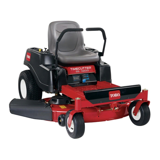
- Page 1 Form No. 3388-238 Rev A TimeCutter ® SS 4200 Riding Mower Model No. 74720—Serial No. 315000001 and Up *3388-238* A Register at www.Toro.com. Original Instructions (EN)
-
Page 2: Figure 1
This product contains a chemical or chemicals known to the State of California to cause cancer, You may contact Toro directly at www.Toro.com for product and accessory information, help finding a dealer, or to register birth defects, or reproductive harm. -
Page 3: Table Of Contents
Contents Cleaning and Storage ..........42 Troubleshooting ............43 Safety ................4 Schematics ..............45 Safe Operating Practices........... 4 Toro Riding Mower Safety ........6 Slope Indicator ............7 Safety and Instructional Decals ......... 8 Product Overview ............12 Controls ...............12 Operation ..............13 Think Safety First ...........13 Testing the Safety-Interlock System......15... -
Page 4: Safety
In these instances, others from serious injury. Toro has refined the statement to convey the meaning of the standard while better matching the product this Operator's •... - Page 5 Service • Always avoid sudden starting or stopping on a slope. If tires lose traction, stop the machine, disengage the blades Safe Handling of Gasoline: and proceed slowly off the slope. To avoid personal injury or property damage, use extra care •...
-
Page 6: Toro Riding Mower Safety
• Maintain or replace safety and instruction decals as necessary. • Use only genuine Toro replacement parts to ensure that original standards are maintained. Toro Riding Mower Safety The following list contains safety information specific to Toro products or other safety information that you must know that may not be included in the ANSI standards. -
Page 7: Slope Indicator
Slope Indicator G011841 Figure 3 This page may be copied for personal use. 1. The maximum slope you can safely operate the machine on is 15 degrees. Use the slope chart to determine the degree of slope of hills before operating. Do not operate this machine on a slope greater than 15 degrees. Fold along the appropriate line to match the recommended slope. -
Page 8: Safety And Instructional Decals
Safety and Instructional Decals Safety decals and instructions are easily visible to the operator and are located near any area of potential danger. Replace any decal that is damaged or lost. 93-7009 1. Warning—don't operate the mower with the deflector up or removed;... - Page 9 119-8815 1. Parking position 4. Neutral 2. Fast 5. Reverse 3. Slow 121-2989 1. Bypass lever position for 2. Bypass lever position for pushing the machine operating the machine Battery Symbols Some or all of these symbols are on your battery 1.
- Page 10 131–3947 1. Trim—slow 3. Mow—fast 2. Tow—medium 131-4036 1. Do not tow or pull weights 2. Read the Operator's greater than 36 kg (80 lbs). Manual.
- Page 11 120-2239 1. Warning—read the Operator's Manual. 5. Warning—do not use split ramps, use a full ramps when transporting machine. 2. Warning—read the instructions before servicing or performing 6. Loss of traction/control hazard, slopes—loss of traction/control maintenance; move the motion control levers to the park on a slope, disengage the blade control switch (PTO), (brake) position, remove the ignition key and disconnect the proceed off the slope slowly.
-
Page 12: Product Overview
Ignition Switch Product Overview The ignition switch has three positions, Off, Run and Start. The key will turn to Start and move back to Run upon release. Turning the key to the Off position will stop the engine; however, always remove the key when leaving the machine to prevent someone from accidentally starting the engine (Figure Throttle/Choke Control... -
Page 13: Operation
Fuel Window Operation The fuel window located on the left hand side of the machine Note: Determine the left and right sides of the machine can be used to verify the presence of gasoline in the tank from the normal operating position. (Figure Think Safety First G014521... -
Page 14: Fuel Safety
Fuel Safety DANGER In certain conditions, gasoline is extremely flammable and highly explosive. A fire or explosion from gasoline can burn you and others and can damage property. • Fill the fuel tank outdoors, in an open area, when the engine is cold. Wipe up any gasoline that spills. -
Page 15: Testing The Safety-Interlock System
8. Start the engine. WARNING 9. While the engine is running, engage the blade-control Gasoline is harmful or fatal if swallowed. Long-term switch, and rise slightly from the seat. exposure to vapors can cause serious injury and illness. Note: The engine should stop. •... -
Page 16: Starting The Engine
Filling the Fuel Tank Starting the Engine Note: Ensure that the engine is shut off and the motion Note: It may be necessary to hold the lever against the stop, controls are in the parked position. in the choke position, while trying to start the engine (Figure 11). -
Page 17: Operating The Blades
Operating the Blades 3. Turn the ignition key to Off and remove the key. The blade-control switch, represented by a power take-off Driving (PTO) symbol, engages and disengages power to the mower blades. This switch controls power to any attachments that Driving the machine benefits from an understanding of draw power from the engine, including the mower deck and what zero-turn-radius mower means. -
Page 18: Driving Forward
Using the Smart Speed Control • Bagging System • Mulching The Smart Speed Control-System lever, located below the operating position (Figure 15), gives the operator a choice to drive the machine at 3 ground speed ranges—trim, tow, This is the fastest speed. The suggested uses for this speed and mow. -
Page 19: Stopping The Machine
Driving Backward Adjusting the Height-of-Cut Note: Always use caution when backing up and turning. Note: The transport position is the highest height-of-cut position or cutting height (115 mm (4.5 inches)) as shown 1. Move the levers to the center, unlocked position. Figure 2. -
Page 20: Positioning The Seat
Adjusting the Motion Control • Upper hole—use this position with the mower deck in the 63mm (2-1/2 inch) and below height-of-cut Levers positions (Figure 19). • Lower hole—use this position with the mower Adjusting the Height deck in the 76mm (3 inch) and above height-of-cut positions (Figure 19). -
Page 21: Grass Deflector
Grass Deflector 5. Move the motion control levers inward to the neutral position and turn the ignition key to the run position. The mower has a hinged grass deflector that disperses Do not start the machine. clippings to the side and down toward the turf. The machine is now able to be pushed by hand. -
Page 22: Operating Tips
Operating Tips Fast Throttle Setting For best mowing and maximum air circulation, operate the engine at the Fast position. Air is required to thoroughly cut grass clippings, so do not set the height-of-cut so low as to totally surround the mower by uncut grass. Always try to have one side of the mower free from uncut grass, which allows air to be drawn into the mower. -
Page 23: Blade Maintenance
Check the cutter blades daily for sharpness, and for any wear or damage. File down any nicks and sharpen the blades as necessary. If a blade is damaged or worn, replace it immediately with a genuine Toro replacement blade. -
Page 24: Maintenance
Maintenance Note: Determine the left and right sides of the machine from the normal operating position. Recommended Maintenance Schedule(s) Maintenance Service Maintenance Procedure Interval • Change the engine oil. After the first 5 hours • Check the safety-interlock system. • Clean and check the air cleaner foam element. •... -
Page 25: Lubrication
Lubrication Engine Maintenance Greasing the Bearings Servicing the Air Cleaner Service Interval: Every 25 hours—Grease all lubrication Service Interval: Before each use or daily—Clean and check points. the air cleaner foam element. Every 50 hours—Replace the air cleaner paper Grease Type: No. 2 General Purpose Lithium Base Grease element. -
Page 26: Servicing The Engine Oil
Servicing the Engine Oil Oil Type: Detergent oil (API service SF, SG, SH, SJ, or higher) Crankcase Capacity: 1.0 L (34 oz) when you do not change the filter; 1.05 L (36 oz) when you change the filter. Viscosity: See the table below. Figure 27 1. -
Page 27: Changing The Engine Oil
g027476 Figure 30 4. Slowly pour approximately 80% of the specified amount of oil into the fill hole (Figure 31). G027475 Figure 29 Changing the Engine Oil Service Interval: After the first 5 hours Every 100 hours (change it more often under a heavy load or in high temperatures). -
Page 28: Servicing The Spark Plug
g027484 Figure 31 g027477 Figure 32 5. Check the oil level; refer to Checking the Engine-Oil Level (page 26). Note: Ensure the oil-filter gasket touches the engine, Changing the Engine-Oil Filter and then an extra 3/4 turn is completed. 2. Fill the crankcase with the proper type of new oil; refer Service Interval: Every 100 hours Changing the Engine Oil (page 27). -
Page 29: Servicing The Spark Plug
Installing the Spark Plug Tighten the spark plug to 20 N-m (15 ft-lb). g027478 Figure 33 1. Spark-plug wire 4. Clean around the spark plug to prevent dirt from falling into the engine and potentially causing damage. 15 ft-lb 20 N-m 5. -
Page 30: Fuel System Maintenance
Fuel System Maintenance DANGER In certain conditions, gasoline is extremely flammable and highly explosive. A fire or explosion g027478 Figure 36 from gasoline can burn you and others and can damage property. • Perform any fuel related maintenance when the Checking the Spark Plug engine is cold. -
Page 31: Replacing The In-Line Fuel Filter
Replacing the In-line Fuel Electrical System Filter Maintenance Service Interval: Every 100 hours—Replace the in-line fuel filter. WARNING Never install a dirty filter if it is removed from the fuel line. CALIFORNIA 1. Park the machine on a level surface and disengage the Proposition 65 Warning blade-control switch. -
Page 32: Servicing The Fuses
5. Slide the rubber cover up the positive (red) cable. Disconnect the positive (red) cable from the battery post (Figure 40). Retain all fasteners. 6. Remove the battery hold-down (Figure 40) and lift the battery from the battery tray. Figure 41 1. -
Page 33: Drive System Maintenance
Drive System Maintenance Checking the Tire Pressure Service Interval: Every 25 hours—Check tire pressure. Maintain the air pressure in the front and rear tires as specified. Uneven tire pressure can cause uneven cut. Check the pressure at the valve stem (Figure 43). -
Page 34: Releasing The Electric Brake
Releasing the Electric Brake Cooling System Maintenance The electric brake releases by manually rotating the link arms forward. Once the electric brake is energized the brake will reset. Cleaning the Engine Screen To release the brake: 1. Turn the ignition key to the Off position or disconnect Service Interval: Before each use or daily—Clean the engine the battery. -
Page 35: Mower Maintenance
If a blade is damaged or worn, replace 2. Curved area 4. Damage it immediately with a genuine Toro replacement blade. For convenient sharpening and replacement, you may want to keep extra blades on hand. Checking for Bent Blades... - Page 36 2. Measurement (position used previously) optimum performance and continued safety conformance 3. Opposing side of blade being moved into measurement of the machine, use genuine Toro replacement blades. position Replacement blades made by other manufacturers may result in non-conformance with safety standards.
-
Page 37: Leveling The Mower Deck
Important: The curved part of the blade must be pointing upward toward the inside of the mower to ensure proper cutting. 2. Install the the curved washer (cupped side toward the blade) and the blade bolt (Figure 50). 3. Torque the blade bolt to 47 to 88 N-m (35 to 65 ft-lb). Leveling the Mower Deck Check to ensure that the mower deck is level any time you install the mower or when you see an uneven cut on your... -
Page 38: Adjusting The Front-To-Rear Blade Slope
Note: Check and adjust the side-to-side blade level 5. Measure between the outside cutting edges and the flat surface (Figure 53). If both measurements are not if you have not checked the setting; refer to Leveling within 5 mm (3/16 inch), an adjustment is required; from Side to Side (page 37). -
Page 39: Removing The Mower
(Figure 58). [1-1/2 inch (38 mm)]. 4. Using a spring removal tool, (Toro part no. 92-5771), remove the idler spring from the deck hook to remove tension on the idler pulley and roll the belt off of the pulleys... -
Page 40: Installing The Mower
5. Route the new belt around the engine pulley and mower pulleys (Figure 59). G005303 6. Using a spring removal tool, (Toro part no. 92-5771), Figure 60 install the idler spring over the deck hook and placing tension on the idler pulley and mower belt (Figure 59). -
Page 41: Cleaning
Cleaning Note: If the mower is not clean after one washing, let it soak for 30 minutes. Then repeat the procedure of washing the underside of the mower. Washing the Underside of the 8. Run the mower again for one to three minutes to Mower remove excess water. -
Page 42: Storage
Storage section. With the spark plug(s) removed from the engine, pour two tablespoons of engine oil into the spark plug hole. Use the starter to crank the engine and Cleaning and Storage distribute the oil inside the cylinder. Install the spark plug(s). -
Page 43: Troubleshooting
Troubleshooting Problem Possible Cause Corrective Action The engine overheats. 1. The engine load is excessive. 1. Reduce ground speed. 2. The oil level in the crankcase is low. 2. Add oil to the crankcase. 3. The cooling fins and air passages 3. - Page 44 Problem Possible Cause Corrective Action There is abnormal vibration. 1. The engine mounting bolts are loose. 1. Tighten the engine mounting bolts. 2. The engine pulley, idler pulley, or blade 2. Tighten the appropriate pulley. pulley is loose. 3. The engine pulley is damaged. 3.
-
Page 45: Schematics
Schematics Electrical Diagram (Rev. A) - Page 46 Notes:...
- Page 47 Notes:...
- Page 48 Customers who have purchased Toro products outside the United States or Canada should contact their Toro Distributor (Dealer) to obtain guarantee policies for your country, province, or state. If for any reason you are dissatisfied with your Distributor's service or have difficulty obtaining guarantee information, contact the Toro importer. If all other remedies fail, you may contact us at Toro Warranty Company.
Need help?
Do you have a question about the TimeCutter SS 4200 74720 and is the answer not in the manual?
Questions and answers