Table of Contents
Advertisement
Quick Links
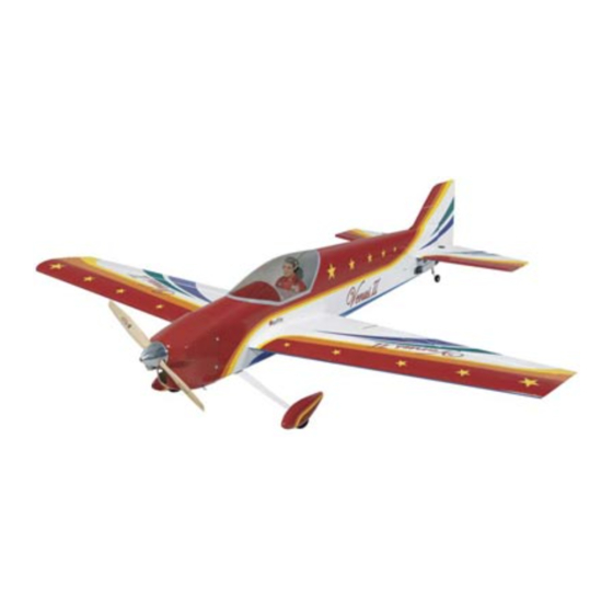
Wingspan: 66 in [1675 mm]
Wing Area: 866 sq in [55.9 dm
Weight: 8.5–9.5 lb [3860–4310 g]
Wing Loading: 22.5–26 oz/sq ft [69–79 g/dm
Length: 69.5 in [1675 mm]
Radio: 4-channel, 6 servos
Engine: .61–.91 cu in [10–15cc] two-stroke,
.91–1.2 cu in [10–20cc] four-stroke
Great Planes
®
Model Manufacturing Co. guarantees this kit to be free from defects in both material and workmanship at the date of
purchase. This warranty does not cover any component parts damaged by use or modification. In no case shall Great Planes' liability
exceed the original cost of the purchased kit. Further, Great Planes reserves the right to change or modify this warranty without notice.
In that Great Planes has no control over the final assembly or material used for final assembly, no liability shall be assumed nor
accepted for any damage resulting from the use by the user of the final user-assembled product. By the act of using the user-assembled
product, the user accepts all resulting liability.
If the buyer is not prepared to accept the liability associated with the use of this product, the buyer is advised to return this
kit immediately in new and unused condition to the place of purchase.
To make a warranty claim send the defective part or item to Hobby Services at the address below:
Include a letter stating your name, return shipping address, as much contact information as possible (daytime telephone number, fax
number, e-mail address), a detailed description of the problem and a photocopy of the purchase receipt. Upon receipt of the package
the problem will be evaluated as quickly as possible.
READ THROUGH THIS MANUAL BEFORE STARTING
CONSTRUCTION. IT CONTAINS IMPORTANT WARNINGS
AND INSTRUCTIONS CONCERNING THE ASSEMBLY
AND USE OF THIS MODEL.
© Copyright 2005
INSTRUCTION MANUAL
2
]
2
]
3002 N. Apollo Dr. Suite 1
Champaign IL 61822 USA
WARRANTY
Hobby Services
™
Champaign, Illinois
(217) 398-8970, Ext 5
airsupport@greatplanes.com
GPMZ0182 for GPMA1027 V1.0
Advertisement
Table of Contents

Related Manuals for GREAT PLANES Venus II


Summary of Contents for GREAT PLANES Venus II
-
Page 1: Instruction Manual
READ THROUGH THIS MANUAL BEFORE STARTING CONSTRUCTION. IT CONTAINS IMPORTANT WARNINGS Champaign, Illinois AND INSTRUCTIONS CONCERNING THE ASSEMBLY (217) 398-8970, Ext 5 AND USE OF THIS MODEL. airsupport@greatplanes.com © Copyright 2005 GPMZ0182 for GPMA1027 V1.0... -
Page 2: Table Of Contents
Optional Supplies and Tools........5 IMPORTANT BUILDING NOTES ........5 For the latest technical updates or manual corrections to the Venus II ARF, visit the Great Planes web site at ORDERING REPLACEMENT PARTS ......6 www.greatplanes.com. Open the “Airplanes” link, and KIT CONTENTS ..............7 then select the Venus II ARF. -
Page 3: Safety Precautions
Do not alter or modify the model, as doing so may result in an unsafe or unflyable model. In a few cases This is a partial list of items required to finish the Venus II the instructions may differ slightly from the photos. In those... -
Page 4: Engine Recommendations
Refer to the recommended engine size range on the front servos (HCAM2721 for Futaba ® cover of the manual. The Venus II was primarily designed to fly ❏ (2) 12" [300 mm] servo extensions for aileron servos on a 1.2 cu in [20cc] four-stroke glow engine, but other engines (HCAM2711 for Futaba) within the size range are suitable. -
Page 5: Optional Supplies And Tools
30-minute (or 45-minute) epoxy, because you will need the working time and/or the additional strength. Optional Supplies and Tools • The Venus II ARF is factory-covered with Top Flite ® MonoKote ®... -
Page 6: Ordering Replacement Parts
ORDERING REPLACEMENT PARTS Replacement parts for the Great Planes Venus II ARF are available using the order numbers in the Replacement Parts List that follows. The fastest, most economical service can be provided by your hobby dealer or mail-order company. -
Page 7: Kit Contents
KIT CONTENTS Kit Contents (Photographed) 1 Fuselage with canopy and belly 6 Wheel Pants (2) 11 70 mm Wheels (2) pan [1/4-20 Blind Nuts (2), 7 Fuel Tank with Hardware 12 Plywood Receiver/Battery Tray 8-32 Blind Nuts (4), 3/16" Gray 8 Tail Gear Wire, Tail Wheel, 13 Wing Joiner and Wing Joiner Brace Pushrod Tubes (4)]... -
Page 8: Preparations
PREPARATIONS ❏ 2. Use a trim iron to thoroughly seal the covering around the firewall, around the air passage cutout at the firewall under the fuselage, and around the formers at the front and back of the wing saddle. During construction there will be several occasions where epoxy cleanup will be necessary. -
Page 9: Assemble The Wings
❏ ❏ 3. Apply at least eight drops of thin CA to the top and bottom of each hinge. Allow enough time between drops so the CA can soak into the hinge rather than running into the ❏ 4. Use epoxy to glue the 1/8" [3 mm] plywood wing joiner hinge gap. - Page 10 CONNECT THE PUSHRODS TO THE SERVO ARMS SO THEY ARE OPPOSITE, AS SHOWN. Note: Set up the ailerons so the servo arms that the ❏ 4. Connect a 12" [300 mm] servo extension wire to each pushrods will be mounted to are opposed. aileron servo.
-
Page 11: Join The Wings
❏ 7. Now that the servos and control horns have been mounted, remove the servo mounting screws and the control horn screws. Add a few drops of thin CA to each screw hole to harden the “threads” in the holes. After the CA has hardened, reinstall all the screws to securely mount the servos and the horns. -
Page 12: Assemble The Fuselage
ASSEMBLE THE FUSELAGE Add the Belly Pan HOW TO CUT COVERING FROM BALSA. ❏ 1. Bolt the wing to the fuselage with two 1/4-20 x 2" [50 mm] To avoid cutting into the balsa, use a soldering iron instead nylon wing bolts and the plywood wing bolt plate. of a hobby knife to cut the covering. -
Page 13: Join The Stabilizer And Fin
❏ 9. Remove the assembly and take out the paper tubes.Then cut them off along the bottom edge of the lines you marked. ❏ 10. Reinsert the paper tubes into the belly pan and reposition the assembly on the wing. Position the tubes as necessary so the ends will be flush with the bottom of the belly pan. - Page 14 ❏ 5. Remove the stabilizer from the fuselage. Taking accurate measurements, use a fine-point felt-tip pen to mark the middle of the stabilizer on the trailing edge. Again with accuracy, mark two more lines 7/16" [11 mm] on both sides of the centerline.
- Page 15 A = A' ❏ 11. When gluing two parts together, one of the things that can be done to achieve the strongest bond possible is to apply glue to both parts being joined (as was done when joining the wing halves). And like the wing, this is important when gluing in the stabilizer—epoxy should be applied liberally in the stab slot in the fuselage and to the stab.
- Page 16 Before joining the rudder to the fin, the tail gear has to shown. Make sure the “torque rod” part of the wire is be put together… perpendicular to the leading edge of the rudder. Bend the wire as necessary. ❏ 17.
-
Page 17: Mount The Servos And Hook Up The Controls
pivot point and use 4-40 x 5/8" [16 mm] Phillips screws and Mount the Servos and the mounting plates to mount the horns. Drill 1/8" [3.2 mm] Hook Up the Controls holes through the rodder for the screws. Note: Trim the rudder horn as shown so it will not interfere with the fuselage. -
Page 18: Mount The Main Landing Gear
Refer to this photo while mounting the servos Mount the Main Landing Gear and hooking up the pushrods. Refer to this sketch while mounting the wheels. 5/32" [4 mm] #6 WASHERS WHEEL COLLAR AS SPACERS AND 6-32 SHCS 5/32" WHEEL COLLARS WITH 6-32 SHCS Bend and cut one pushrod to join with the other. -
Page 19: Mount The Engine
❏ 4. Mount the engine mount to the firewall with four Mount the Engine 8-32 x 1-1/4" [32 mm] SHCS, four #4 lock washers and four #4 flat washers, but do not tighten the screws yet. ❏ 1. Determine which Engine Mounting Template from the back of the manual you will use. -
Page 20: Mount The Cowl
Mount the Cowl These are the cutting bits recommended for cutting the holes in the cowl. ❏ 2. With the cowl in position, use a fine-point felt-tip pen to mark both sides of the aft edge of the cowl onto the fuselage. -
Page 21: Hook Up The Throttle
❏ 5. Remove the cowl. Enlarge the holes in the cowl only Hook Up the Throttle with a 1/8" [3.2 mm] drill. Then, mount the cowl to the fuselage with four #4 x 5/8" [16 mm] screws, #4 lock washers and #4 flat washers. As you have been doing all along, remove the screws, harden the holes with a few drops of thin CA and allow to harden. -
Page 22: Final Assembly
Refer to the following photo while FINAL ASSEMBLY completing the radio installation. Finish Radio Installation ❏ 4. Mount the receiver and battery pack to the forward or aft radio trays with 1/4" [6 mm] R/C foam (not included) and the Velcro strips. ❏... -
Page 23: Apply The Decals
GET THE MODEL READY TO FLY Check the Control Directions and Center the Servos ❏ 1. With the radio system connected and operating, turn on the transmitter and receiver. 4-CHANNEL RADIO SETUP (STANDARD MODE 2) ❏ 4. Mount the canopy to the fuselage with four #2 x 3/8" [9.5 mm] button-head screws. -
Page 24: Set The Control Throws
If, after the smoothness and stability, but the model will then be less you have become accustomed to the way the Venus II ARF flies, you would like to change the throws to suit your aerobatic and may require more speed for takeoff and make it more difficult to slow for landing. -
Page 25: Balance The Model Laterally
❏ 3. If the tail drops, the model is “tail heavy” and weight Charge the Batteries must be added to the nose to balance. If the nose drops, the model is “nose heavy” and weight must be added to the tail Follow the battery charging instructions that came with your to balance. -
Page 26: Range Check
• To stop a glow engine, cut off the fuel supply by closing off Range Check the fuel line or following the engine manufacturer’s recommendations. Do not use hands, fingers or any other Ground check the operational range of your radio before the body part to try to stop the engine. -
Page 27: Checklist
Because of this, you may be more likely to overlook certain The Venus II ARF is a great-flying model that flies smoothly checks and procedures that should be performed before the and predictably. -
Page 28: Takeoff
(anticipating rudder corrections that will be required to maintain heading), remember to throttle back at the top, and The Venus II is a stable, honest flier (as any pattern-type make certain you are on the desired rates (high/low rates). plane should be). Takeoff is straightforward—just remember... -
Page 29: Engine Mounting Templates
ENGINE MOUNTING TEMPLATES (O.S. 4-Stroke- Angle-Mounted) BOTTOM OF FUSELAGE CUT OUT Drill 13/64" [5.2mm] DOTTED LINE or 3/16" [4.8mm] holes (O.S. 2-Stroke- Angle-Mounted) Angled Engine Mounting Template For O.S. 1.20 Surpass BOTTOM OF FUSELAGE CUT OUT DOTTED LINE Drill 13/64" [5.2mm] or 3/16"... - Page 30 OTHER HOBBY ITEMS AVAILABLE O.S. ® FS-120S-E Surpass ™ (OSMG0930) Bore: 1.22 in (30.4 mm) Stroke: 1.08 in (27.5 mm) Power Output: 1.9 bhp @ 11,000 rpm Weight (with muffler): 33.3 oz (944g) Practical RPM Range: 2,000-11,000 O.S. ® .91 FX (OSMG0591) Bore: 27.7 mm (1.090") Stroke: 24.8 mm (0.976")
- Page 31 OTHER HOBBY ITEMS AVAILABLE Great Planes Venus .40 ARF (GPMA1025) Wingspan: 55 in (1397 mm) Wing Area: 568 sq in (36.6dm2) Weight: 4.8-5.3 lb (2177-2404g) Wing Loading: 19.5-21.5 oz/sq ft (60-66g/dm2) Length: 54 in (1372 mm) Requires: 2-stroke .40-.51 or 4-stroke .52-.70 engine, 4-channel radio w/5 standard servos Make the most of your low-wing flying skills! The Venus 40 offers precise handling for master F3A type contest maneuvers - but with its easy maneuverability, slow landings and 10-12 hour assembly, this model is also a great choice for everyday flying.
- Page 32 BUILDING NOTES Kit Purchased Date: _______________________ Date Construction Finished: _________________ Where Purchased:_________________________ Finished Weight: __________________________ Date Construction Started: __________________ Date of First Flight: ________________________ FLIGHT LOG...
Need help?
Do you have a question about the Venus II and is the answer not in the manual?
Questions and answers