Table of Contents
Advertisement
Quick Links
Advertisement
Table of Contents
Troubleshooting

Related Manuals for Hitachi DZ-GX5020A K


Summary of Contents for Hitachi DZ-GX5020A K
- Page 1 No. 0614E DZ-GX5080A DZ-GX5020A SERVICE MANUAL DZ-GX5020A (K) DZ-GX5000A DZ-GX5080A DZ-GX5020A DZ-GX5000A DO NOT RESELL OR DIVERT IMPROPERLY SPECIFICATIONS AND PARTS ARE SUBJECT TO CHANGE FOR IMPROVEMENT DVD VIDEO CAMERA/RECORDER December 2006...
-
Page 2: Table Of Contents
Table of Contents 4-5-1 Trouble diagnosis fl owchart ....4-22 1 Safety Precaution for Repair ....1-1 4-5-2 Reassembly to enable service position .. 4-31 1-1 Cautions ............ 1-1 4-6 Procedure for Removing Disc from 1-2 Electrostatic Protection Measures ..... 1-2 Faulty DVD Video Camera/Recorder .. - Page 3 6 Adjustment .......... 6-1 7 Exploded View ........7-1 6-1 Creating Reference Data ......6-1 7-1 DZ-GX5080A ..........7-1 6-1-1 Checking Reference Data ...... 6-1 7-2 DZ-GX5020A/GX5000A ......7-2 6-1-2 List of Jigs and Tools used when Creating Reference Data ........6-3 S Wiring and Schematic Diagrams ..
-
Page 4: Safety Precaution For Repair
The use of a substitute replacement component which does not have the same safety characteristics as the HITACHI recommended replacement one, shown in the parts list in this Service Manual, may create shock, fi re, or other hazards. Product safety is continuously under review and new instructions are issued from time to time. -
Page 5: Electrostatic Protection Measures
Safety Precaution for Repair > Electrostatic Protection Measures / Cautions When Handling DVD Drive 1-2 Electrostatic Protection Measures Semiconductor components can be damaged by static electricity charged on clothes, human body, etc. Take great care when handling components to avoid electrostatic damage, and perform servicing in an environment where grounding is complete. -
Page 6: Lead-Free Solder
Safety Precaution for Repair > Lead-Free Solder 1-4 Lead-Free Solder The printed circuit board that uses lead-free solder is adopted. To protect the global environment, use the recommended lead-free solder also during servicing. Read and observe the following before soldering: Caution ALWAYS wear protective goggles during soldering so that no solder smoke or scattered solder enters the eye. - Page 7 Safety Precaution for Repair > Lead-Free Solder (5) Cautions when using lead based solder It is recommended that you use lead-free solder when servicing, but it is also possible to service using lead based solder. However, if lead based solder is used for servicing, take care with the following: 1) Before using lead based solder, remove the lead-free solder completely from the point to be soldered.
-
Page 8: Notes When Using Service Manual
Safety Precaution for Repair > Notes When Using Service Manual 1-5 Notes When Using Service Manual (1) Value units used in parts list Certain symbols are indicated as shown below for value units of resistors, capacitors and coils in parts list. When you read them, note the following regular indications: Parts Indication in list Regular indication... - Page 9 Safety Precaution for Repair > Notes When Using Service Manual (4) Indicating model names The indication of models is defi ned as follows: 1) The common parts of model names are omitted. Example: When indicating VM-D975LA and VM-D875LA: VM-D975LA/D875LA, D975LA/D875LA 2) If there is no difference in models going to different destinations, the indication of destination is omitted.
-
Page 10: General Description
General Description 2-1 Overview The DZ-GX5080A/GX5020A/GX5000A DVD video camera/recorders incorporate a CCD image sensor with a total of approx. 680,000 pixels: HDD is not mounted. The compatible recording/playback media are equivalent to those of conventional models as shown in Table 2-1-1. Table 2-1-2 shows the differences between DZ-GX5080A, DZ-GX5020A and DZ-GX5000A. -
Page 11: Servicing Method
General Description > Overview 2-1-1 Servicing method Refer to the following table and perform the designated, appropriate servicing. Any changes that occur in the service method will be published using service bulletin, etc. Do not perform any servicing other than that described in this manual. Table 2-1-3 Servicing method Servicing method Parts Name... -
Page 12: Features
General Description > Features / Specifi cations 2-2 Features LED Light The DZ-GX5080A incorporates an LED light that uses two highly luminous and long-life white light-emitting diodes (LED). This LED light can also be used when recording a movie: Use the button to turn the LED light on and off. - Page 13 General Description > Specifi cations Item Specifi cations (*1) Maximum DVD-RAM (per side) Approx. 999 number of (*2) SD memory Card (32MB) Approx. 180 (in FINE mode) recordable photos Recording DVD-RAM/DVD-RW (VR mode) Movie: Conforming to DVD video recording (DVD-VR) format format Sound: Dolby Digital...
- Page 14 General Description > Specifi cations Item Specifi cations Provided accessories AC adapter/charger (DZ-ACS3) Battery (DZ-BP07PW) AV/S output cable Lens cap Lens cap string Shoulder strap Power cable DC power cord Software CD-ROM [not provided with DZ-GX5020A/GX5000A] PC connection cable [not provided with DZ-GX5020A/GX5000A] Disc cleaning cloth Specifi...
-
Page 15: Major Differences From Previous Models
General Description > Major Differences from Previous Models 2-4 Major Differences from Previous Models : Same as on left ← Item DZ-GX5080A/GX5020A/GX5000A DZ-BX37A/BX35A Dimensions (W × H × D) and Approx. 2-1/2" × 3-9/16" × 5-3/16" Approx. 1-7/8" × 3-1/2" × 5-3/16" shape DZ-GX5080A DZ-GX5020A... - Page 16 General Description > Major Differences from Previous Models Item DZ-GX5080A/GX5020A/GX5000A DZ-BX37A/BX35A Approx. 3.2W Power consumption (DVD-RAM ← used, FINE mode) Approx. 420g DZ-GX5080A: Approx. 425g Weight DZ-GX5020A/GX5000A: Approx. 420g Approx. 18 min/ Maximum XTRA ← Variable: Approx. 3 - 10 Mbps time of Approx.
- Page 17 Windows® XP Professional Edition or higher See the following Websites to fi nd out whether the provided software can be used on Windows Vista: URL:http://www.pixela.co.jp/oem/hitachi/e/index.html URL: http://dvdcam-pc.support.hitachi.ca/ *2: Mac OS X v10.3.9, v10.4.2-v10.4.8 *3: Mac OS X v10.2.8/v10.3.4-v10.3.9/v10.4.1-v10.4.3 2 - 8...
-
Page 18: Compatibility Of Recorded Dvd And Corresponding Recording Media
The DVD-R can be played back on other Hitachi DVD video camera/recorders without being fi nalized. However, be sure not to record or fi nalize a DVD-R using other Hitachi DVD video camera/recorders: Doing so will make the DVD-R unusable. - Page 19 The DVD-RW(VF) can be played back on other Hitachi DVD video camera/recorders without being fi nalized. However, be sure not to record or fi nalize the DVD-RW(VF) using other Hitachi DVD video camera/recorders: Doing so will make the DVD-RW(VF) unusable.
-
Page 20: Corresponding Recording Media
General Description > Compatibility of Recorded DVD and Corresponding Recording Media 2-5-2 Corresponding Recording Media M: Movie Still RP: Recording/Playback possible Only playback possible Table 2-5-1 List of Compatible Recording Media Non-compatibility 8 cm disc Card Multi- DVD- Model DVD-R DVD-RW Note memory media... -
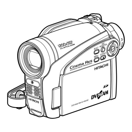
Page 21: Names Of Parts
General Description > Names of Parts 2-6 Names of Parts 2 - 12... - Page 22 General Description > Names of Parts 2 - 13...
- Page 23 General Description > Names of Parts 2 - 14...
- Page 24 General Description > Names of Parts Accessories 2 - 15...
-
Page 25: List Of Abbreviations And Terms For Dvd Video Camera/Recorders
General Description > List of Abbreviations and Terms for DVD Video Camera/Recorders 2-7 List of Abbreviations and Terms for DVD Video Camera/Recorders Index Abbreviation/Term Explanation See Dolby AC3. CPRM Content Protection for Recordable Media: Copyright protection function that is suitable for online distribution of music. CSP IC Chip Scale Package IC or Chip Size Package IC: This IC was made compact by arranging pins under the package. - Page 26 General Description > List of Abbreviations and Terms for DVD Video Camera/Recorders Index Abbreviation/Term Explanation See MultiMediaCard. MPEG Motion Picture Experts Group: Standard related to compression of digital video and audio. MPEG2 is a higher standard of MPEG and is applied to video (movie) requiring higher quality.
-
Page 27: Description Of Operation
Description of Operation 3-1 Description of Structure The DZ-GX5080A/GX5020A/GX5000A is produced based on the previous DZ-BX37A/BX35A. Therefore the confi guration of components closely resembles that of DZ-BX37A/BX35A. (1) Major differences from DZ-BX37A/BX35A 1) The shape, design and color at the top of product and on the left (LCD monitor side) are different. -
Page 28: Description Of Newly Adapted Technology
Description of Operation > Description of Structure / Description of Newly Adapted Technology ( f ) ( i ) Fig. 3-1-1 Confi guration of circuit boards and their mounting locations 3-2 Description of Newly Adapted Technology 3-2-1 LED Light The DZ-GX5080A incorporates an LED light that uses two highly luminous and long-life white light-emitting diodes (LED), in place of the fl... -
Page 29: Troubleshooting
Troubleshooting 4-1 Procedure for Troubleshooting Perform troubleshooting in the order shown in Fig. 4-1-1. Note: 1) Before troubleshooting or servicing, be sure to obtain customer approval for the following: a) The recorded contents on disc may be lost depending on the details and situation of fault (defect). -
Page 30: Messages And Troubleshooting
Troubleshooting > Messages and Troubleshooting 4-2 Messages and Troubleshooting Some messages may appear on the LCD screen or in the viewfi nder during operation. If a message appears, check the following, and then perform the appropriate action, according to the message content: 1) Is the disc bottom/surface reversed when using a single-sided disc? If so, reload the disc properly. - Page 31 Troubleshooting > Messages and Troubleshooting Cause/condition for Message Troubleshooting message to appear Cannot execute. Appears if an attempt is made to Divide scenes one by one. Unselect multiple scenes. select multiple scenes for division: The specifi cations state that dividing multiple scenes is impossible.
- Page 32 Troubleshooting > Messages and Troubleshooting Cause/condition for Message Troubleshooting message to appear Card is not formatted. Appears when an unformatted card or a Choose “YES” and designate it when Format the card now? card formatted on PC was loaded. formatting card (deleting all recorded data).
- Page 33 Troubleshooting > Messages and Troubleshooting Cause/condition for Message Troubleshooting message to appear Data error in all image fi le. Appears when reading/writing of Refer to “4-3-5 Cleaning disc and Repair all data now? recorded fi les cannot be performed optical pickup” and clean the disc. because the disc is dirty.
- Page 34 Troubleshooting > Messages and Troubleshooting Cause/condition for Message Troubleshooting message to appear Disc error has occurred. Appears when the disc could not be Refer to “4-3-5 Cleaning disc and Finalizing is not complete. fi nalized because it was dirty. optical pickup” and clean the disc. Or replace the disc.
- Page 35 Troubleshooting > Messages and Troubleshooting Cause/condition for Message Troubleshooting message to appear Disc error has occurred. Appears when a recorded fi le cannot Clean the disc, referring to “4-3-5 Unfi nalize is not completed. be read or written. If no recovery is Cleaning disc and optical pickup”, or made even when the disc is cleaned replace it.
- Page 36 Troubleshooting > Messages and Troubleshooting Cause/condition for Message Troubleshooting message to appear Disc is not formatted. Appears when a brand-new DVD-RW/ When recording on the DVD video Format the disc now? +RW was loaded. camera/recorder, choose “YES/ VR Mode/VF Mode” and designate it. [Displayed only when DVD- Appears when reading or writing from/to Refer to “4-3-5 Cleaning disc and...
- Page 37 Troubleshooting > Messages and Troubleshooting Cause/condition for Message Troubleshooting message to appear DVD-RAM disc. Finalize is Appears when the FINALIZE button A DVD-RAM does not need to be not required. was pressed with a DVD-RAM used. fi nalized: Wait until the message disappears.
- Page 38 Troubleshooting > Messages and Troubleshooting Cause/condition for Message Troubleshooting message to appear NO DISC Appears if no disc is loaded. Load a disc Appears when a disc that cannot be used Check the type of disc, and load a on the DVD video camera/recorder has disc been loaded.
- Page 39 Troubleshooting > Messages and Troubleshooting Cause/condition for Message Troubleshooting message to appear There was no scene which Appears when only multiple locked Use the Disc Navigation function to can be deleted. scenes were selected using the Disc unlock the scenes, and then restart Navigation function, and deleting them operation.
-
Page 40: Display Of Error Codes And Troubleshooting
Troubleshooting > Display of Error Codes and Troubleshooting 4-3 Display of Error Codes and Troubleshooting Restriction: The information included in this section is exclusively for service personnel: Do not disclose it to persons other than service engineers. The DVD video camera/recorder is equipped with a self-diagnostic function: If the DVD video camera/recorder detects any problem, it will choose an appropriate error code (4-digit alphanumeric) and store it in fl... -
Page 41: Details Of Error Code Display
Troubleshooting > Display of Error Codes and Troubleshooting 4-3-2 Details of error code display Up to eight error codes of problems can be displayed Error Code with the dates/times when the problems occurred. [Error Code] Date Time If the same problem occurs repeatedly, it will be [0400]11111405 [0000]00000000 judged as one problem, and the same error code will... - Page 42 Troubleshooting > Display of Error Codes and Troubleshooting Error code Contents of problem Troubleshooting 5122 Video or photo fi le cannot be opened. Clean the disc and optical pickup, referring to “4-3-5 Cleaning disc and optical pickup”. Replace the disc. Replace the DVD drive unit.
-
Page 43: Disc Load Check Flowchart
Troubleshooting > Display of Error Codes and Troubleshooting 4-3-4 Disc Load Check Flowchart Check the following only when an instruction for referring to this chart is given in “Table 4-3-1 Major Error Codes and Troubleshooting” on the previous item. Caution Laser light striking the eye may cause your eyesight to be lost: For safety, be sure to remove any power supply (AC adapter/charger, battery, etc.) from the DVD video camera/recorder before starting work. -
Page 44: Cleaning Disc And Optical Pickup
KS2424-X00 Toraysee (cleaning cloth only) produced by Toray b) LF-K200DCJ1 DVD-RAM/PD disc cleaner (cleaning cloth and cleaning liquid) produced by Panasonic c) OC-CS MO disc cleaner (cleaning cloth and cleaning liquid) produced by Hitachi Maxell (2) Cleaning optical pickup Note: Do not clean the optical pickup needlessly. -
Page 45: Checking Versions Of Firmware And Updating
Troubleshooting > Display of Error Codes and Troubleshooting / Checking Versions of Firmware and Updating Caution Laser light striking the eye may cause your eyesight to be lost: For safety, be sure to remove any power supply (AC adapter/charger, battery, etc.) from the DVD video camera/recorder before starting work. 3) Check to see whether the optical pickup is dirty: If it is not dirty, cleaning is not necessary. -
Page 46: Checking Fi Rmware Versions
Troubleshooting > Checking Versions of Firmware and Updating 4-4-1 Checking fi rmware versions (1) Version check screen display method 1) Attach the AC adapter/charger to power the DVD video camera/recorder. 2) Set the power switch to the position shown below. Then operate the DVD video camera/recorder while watching the LCD monitor or viewfi... -
Page 47: Updating Fi Rmware
Troubleshooting > Checking Versions of Firmware and Updating Information: 1) The version number of loader fi rmware cannot be confi rmed on the information display/version screen because of design limitations. 2) With actual screens, fi gures and letters will appear in digits displayed as x on illustrations. 3) The number at the bottom right of screens shows the operation hours of disc drive unit: Use this for reference to determine how long the customer has used the DVD video camera/recorder. - Page 48 Troubleshooting > Checking Versions of Firmware and Updating Updating Start Screen System Update Screen Loader Update Screen Firmware Update Firmware Update Firmware Update Updating system. Updating Loader. Start Firmware update. Do not turn off power. Do not turn off power. Camera Update Screen Drive (Main) Update Screen Drive (Core) Update Screen...
-
Page 49: Trouble Diagnosis
Troubleshooting > Trouble Diagnosis 4-5 Trouble Diagnosis Information: 1) Use the DZ-ACS3 AC adapter/charger to power the DVD video camera/recorder for trouble diagnosis. 2) The trouble diagnosis fl owchart was prepared presupposing that the circuit boards have been normally attached and connected. Therefore, make sure beforehand that the circuit boards are correctly connected, that connectors and cables are not damaged, and that the status of their connections is correct. -
Page 50: Trouble Diagnosis Fl Owchart
Troubleshooting > Trouble Diagnosis 4-5-1 Trouble diagnosis fl owchart Interpreting the trouble diagnosis fl owchart: 1) If removing any component is stated in the fl owchart, remove that component, referring to “5. Disassembly and Reassembly”. 2) If “Solder a lead wire to check point” is stated, solder a lead wire of approx. 10 cm according to the list of check point: Be sure to remove the lead wire after trouble diagnosis is fi... - Page 51 Troubleshooting > Trouble Diagnosis Recognition of DVD does not start even if a normal DVD is loaded. List of check points Lead wire Location on Circuit board Remove the MAN circuit soldered Symptom circuit board (side) board, and solder a lead or not wire to check points R7036...
- Page 52 Troubleshooting > Trouble Diagnosis Message "DISC ACCESS" does not disappear Message "Write protected. Check disc" appears even if a normal DVD is loaded. even if a DVD with no write-protect is loaded. Replace the DVD drive unit. Replace the DVD drive unit. Message "Disc is not formatted.
- Page 53 Troubleshooting > Trouble Diagnosis No image appears in viewfinder. Is video signal output Refer to "No video signal from the AV output from AV output jack". jack? Does image appear Refer to "No image on the LCD monitor? appears on LCD monitor". Replace EVF unit.
- Page 54 Troubleshooting > Trouble Diagnosis Camera recorder image is abnormal List of check points Lead wire Location on Circuit board Symptom soldered Remove the GSL2-L/ circuit board (side) or not GSL3-L circuit board, and solder a lead wire to TL7021 MAN (B) Need not check points TL7028...
- Page 55 Troubleshooting > Trouble Diagnosis Block noise occurs during recording of video. No audio from AV output jack. No sound from Replace the MAN Replace the MAN speaker during circuit board. circuit board. playback of video? AVJ2-L/AVJ3-L circuit faulty No sound from speaker during playback of video Is audio signal output Refer to "No audio signal from the AV output...
- Page 56 Troubleshooting > Trouble Diagnosis DISC EJECT button does not operate. Is recognition sound Disc Eject button faulty: heard when the DISC TL7041 (EJECT_SW): Set to service position (A). Replace the rear case. EJECT button is (*1) pressed? *1: When DISC EJECT button is pressed. Does "EJECT"...
- Page 57 Troubleshooting > Trouble Diagnosis Operation buttons on L case do not function. List of check points Lead wire Location on Remove the L block Circuit board Symptom soldered circuit board (side) or not TL7060 MAN (B) Need not TL7061 MAN (B) Need not TL7062 MAN (B)
- Page 58 Troubleshooting > Trouble Diagnosis REC button does not operate. List of check points Lead wire Location on Circuit board soldered Symptom circuit board Set to service position (A). (side) or not TL7037 MAN (B) Need not TL7037 (REC_KEY): REC button faulty: (*1) Replace the rear case.
-
Page 59: Reassembly To Enable Service Position
Troubleshooting > Trouble Diagnosis 4-5-2 Reassembly to enable service position Cautions Laser light striking the eye may cause your eyesight to be lost: For safety, be sure to remove any power supply (AC adapter/charger, battery, etc.) from the DVD video camera/recorder before starting work. - Page 60 Troubleshooting > Trouble Diagnosis Use the reverse procedure of removal to reattach the GSL2-L/GSL3-L circuit board (camera block), MAN circuit board, rear block and front block to the R block. Securely connect the MAN circuit board, DVD drive unit and GSL2-L/GSL3-L circuit board at this time. (a) GSL2-L/GSL3-L circuit board (b) Camera block (c) MAN circuit board...
- Page 61 Troubleshooting > Trouble Diagnosis (2) Setting to service position (B) Service position (B) is used to troubleshoot the LCD monitor system and operation button system on L side case: Use the check points on MAN circuit board for troubleshooting. After removing the L block, plug the connector of speaker cables and the LMF2-L/LMF3-L circuit board into MAN circuit board.
-
Page 62: Procedure For Removing Disc From Faulty Dvd Video Camera/Recorder
Troubleshooting > Procedure for Removing Disc from Faulty DVD Video Camera/Recorder 4-6 Procedure for Removing Disc from Faulty DVD Video Camera/Recorder 4-6-1 Items to be checked Connect the AC adapter/charger or charged battery (power supply), make sure that the ACCESS indicator turns off, and then press the DISC EJECT button again. -
Page 63: System Resetting/Resetting Camera Functions
Troubleshooting > System Resetting/Resetting Camera Functions 4-7 System Resetting/Resetting Camera Functions The DVD video camera/recorder has two types of reset function: “System reset” and “Resetting camera functions”. The reset operation will return the various settings to the defaults when the DVD video camera/recorder was shipped form factory. - Page 64 Troubleshooting > System Resetting/Resetting Camera Functions Yes: Will be reset Table 4-7-1 List of items to be reset No: Will not be reset Camera System Default at Item function Setting range Remarks Memo reset factory reset Camera Functions Setup Program AE Auto Auto, Sports, Portrait, Spotlight, Sand &...
-
Page 65: System Reset Procedure
Troubleshooting > System Resetting/Resetting Camera Functions 4-7-2 System reset procedure Note: 1) Always perform system reset after completing repair: System reset will erase all error codes stored in fl ash memory. 2) Remove the disc before executing system reset: Executing system reset with a +RW disc loaded may erase the recorded data. -
Page 66: Disassembly And Reassembly
Disassembly and Reassembly Note: Even if the shapes of parts are different, the following disassembly procedure, using the DZ- GX5080A, is the same for all models. 5-1 Items to Be Checked [A] M1.7x4(Silver) (1) Checking Disc 1) [A] Connect the AC adapter/charger or battery to the DVD video camera/recorder, and set the power switch to “OFF”... -
Page 67: Order Of Disassembly
Disassembly and Reassembly > Order of Disassembly 5-2 Order of Disassembly 1) Refer to the disassembly fl owchart in Figs. 5-2-1 for the order of removing each component. Unless otherwise specifi ed, use the reverse procedure to reassemble the removed components. 2) When replacing the MAN circuit board, it is recommended that you back up the EEPROM data in advance, referring to “5-4 EEPROM data backup and write”;... -
Page 68: Disassembly
Disassembly and Reassembly > Disassembly 5-3 Disassembly Information: Numbers in the disassembly procedure diagrams are step numbers of disassembly procedures, and letters in brackets [ ] show the types of screw. (1) Adjustment Cover 1) Open the LCD monitor section (b) in the direction of the arrow. -
Page 69: L Block
Disassembly and Reassembly > Disassembly (3) L Block 1) Remove the six screws [A]. 2) Open the jack cover (e) and then remove the screw [G]. 3) Open the L block in the direction of the arrow from the rear side. 1) [A] Take care at this time that the LMF2-L/ 1) [A]... -
Page 70: Front Block
Disassembly and Reassembly > Disassembly (4) Front Block 1) Remove the AVJ2-L/AVJ3-L circuit board (c) 2) [A] from MAN circuit board (b) in the direction of the arrow. 2) Open the jack cover (d) and then remove the 3) [G] four screws [A]. -
Page 71: Man Circuit Board And Rear Block
Disassembly and Reassembly > Disassembly (5) MAN Circuit Board and Rear Block Information: Before replacing the MAN circuit board, refer to “5-4 EEPROM data backup and write”. 1) Remove the hand strap (c) from R case (d). 2) Disconnect the fl at cable of the EVF unit. 3) Remove the three screws [A]. -
Page 72: Rear Case And Evf Unit
Disassembly and Reassembly > Disassembly (6) Rear Case and EVF Unit 1) Pull out the EVF unit (b) in the direction of (a) Rear case (b) EVF unit the arrow. (c) Eye cup 3) [A] 2) Remove the eye cup (c) in the direction of the arrow. -
Page 73: Back-Up Battery, Sdl Frame And Sdl Circuit Board
Disassembly and Reassembly > Disassembly (8) Back-up Battery, SDL Frame and SDL Circuit Board 1) Use tweezers, etc. to remove the backup battery (a) in the direction of the arrow. Take care not to damage the battery holder (d) on SDL circuit board at this time. 2) Disconnect the two fl... -
Page 74: Top Plate
Disassembly and Reassembly > Disassembly (9) Top Plate 1) Remove the screw [B]. 2) Remove the screw [A]. 3) Remove the top plate (a) in the direction of the arrow. 2) [A] [A] M1.7×4 (Silver) [B] M1.7×2.5 (Silver) (a) Top plate (b) MAN circuit board 2) [A] 1) [B]... -
Page 75: Dvd Drive Unit And R Case
Disassembly and Reassembly > Disassembly (11) DVD Drive Unit and R Case 1) Disconnect the fl at cable. 2) Remove the two screws [A]. 3) Remove the two screws [G], and then remove the DVD drive unit (a). Note: The DVD drive unit is a precision component: Take great care when handling it. Do not subject the DVD drive unit to any impact: Doing so could cause a fault. -
Page 76: Lock Unit
Disassembly and Reassembly > Disassembly (12) Lock Unit 1) With the disc insertion block closed, remove 3) [B] the screw [D]. 2) Move the lock slider (c) in the direction of the arrow to open the disc insertion block. 3) Remove the four screws [B]. Caution during disassembly and reassembly: Be sure to close the disc insertion block before tightening the screw on the switch... -
Page 77: Lcd Unit And L Case
Disassembly and Reassembly > Disassembly (13) LCD Unit and L Case 1) Disconnect the fl at cable. 2) Remove the two screws [E], taking care not to lose the LCD ground plate (c), which will be detached at this time. Note: Take great care when handling the LCD unit. -
Page 78: Lcd Case U And Fulcrum Unit
Disassembly and Reassembly > Disassembly (14) LCD Case U and Fulcrum Unit 1) Turn the fulcrum unit (b) 90° in the direction of the arrow. 2) Remove the three screws [A]. 3) Release the seven tabs and remove the LCD case U (a), taking care not to lose the MR sheet (c), which will be detached at this time. -
Page 79: Lcd Case B
Disassembly and Reassembly > Disassembly (15) LCD Case B 1) Remove the screw [D]. 2) Remove the LCD case B (a) in the direction of the arrow. Note: Take care when handling the LCD circuit board (b), monitor sheet (c), and LCD panel/back light unit (d) in the LCD frame (e) : Adherence of foreign object, such as dust, to them, or any scratches or impact, could cause a fault. -
Page 80: Avj2-L/Avj3-L Circuit Board
Disassembly and Reassembly > Disassembly (16) AVJ2-L/AVJ3-L Circuit Board 1) Remove the AVJ2-L/AVJ3-L circuit board (a) from the FRT2-L/FRT3-L circuit board (b) in the direction of the arrow. [G] M1.7×4 (Silver) 2) Remove the two screws [G]. 3) Remove the ground plate (c) in the direction of the arrow. -
Page 81: Lens Frame, Lens Unit, Cushion And Crystal Filter
Disassembly and Reassembly > Disassembly (18) Lens Frame, Lens Unit, Cushion and Crystal Filter 1) Disconnect the fl at cable. 2) Remove the screw [C]. [B] M1.7X2.5 3) Turn the GSL2-L/GSL3-L circuit board (d) (Silver) up in the direction of the arrow. [C] M1.7X3 4) Remove the two screws [D] and then remove (Silver) -
Page 82: Eeprom Data Backup And Write
Disassembly and Reassembly > EEPROM Data Backup and Write 5-4 EEPROM Data Backup and Write Perform this work whenever you replace the MAN circuit board on which the EEPROM is mounted. Create a backup fi le of the data in EEPROM to be replaced in a PC, and write the backup fi le to new EEPROM: Some adjustment items that are performed after replacement can be omitted. - Page 83 Disassembly and Reassembly > EEPROM Data Backup and Write Note: Always connect the Halcyon connector before connecting the DC power cord to the DVD video camera/recorder: Connecting the Halcyon connector after powering the DVD video camera/ recorder could cause a fault. Adjustment cover Flat-bladed...
-
Page 84: Backup Method
Disassembly and Reassembly > EEPROM Data Backup and Write 5-4-1 Backup Method ADJUST MENU screen BACKUP FILE SELECT screen MANUAL ADJUSTMENT PROGRAM for SERVICE STATION ×××× Look in (T): MODEL NAME: ADJUST MENU DATA INITIALIZE VIDEO LEVEL BURST LEVEL backup File name (N): Save (S) AUTO FUCUS... -
Page 85: Write Method
Disassembly and Reassembly > EEPROM Data Backup and Write 5-4-2 Write Method 3) Choose Backup Data Write. Restrictions: 4) Click the EXECUTE button on DATA Never write data of any other product. INITIALIZE MENU screen to proceed with The EEPROM data includes adjustment the WRITE FILE SELECT screen. -
Page 86: Adjustment
Adjustment 6-1 Creating Reference Data The reference data is necessary for adjustment: The adjustment software will not operate normally without it. Before adjustment, be sure to create the reference data, using the same model (with normal camera block) as the one to be adjusted. The reference data is used to reduce the difference between environments of servicing site and factory (color temperature of light box, etc.). -
Page 87: Data
Adjustment > Creating Reference Data Information: The reference data is usually created once for each model because it is recorded on hard disk drive (HDD) of PC with the adjustment software. However, creating reference data again is necessary in the following cases: a) When performing adjustment using a light box that is different from that used when the reference data was created. - Page 88 Adjustment > Creating Reference Data 6-1-2 List of Jigs and Tools used when Creating Reference Data Halcyon connector Adjustment software Parts No. TP14391 Note: Create the data using the adjustment software downloaded from Intranet. Personal computer (PC) Computer on which any of the following OS operates and which has a (*1) fl...
- Page 89 Adjustment > Creating Reference Data 6-1-3 Power Supply and Materials for Creating Reference Data 1) DVD video camera/recorder (for creating reference data) that is the same model as the one to be adjusted and whose camera block is operating normally. Note: It is recommended that you use a brand-new unit of the same model when creating the reference data.
- Page 90 Adjustment > Creating Reference Data Note: Always connect the Halcyon connector before connecting the DC power cord to the DVD video camera/recorder : Connecting the Halcyon connector after powering the DVD video camera/recorder could cause a fault. Color Monitor Light box To VIDEO IN Front 30-50cm...
- Page 91 Adjustment > Creating Reference Data 6-1-5 Settings when Creating Reference Data When the connections for creating reference data are complete, set the DVD video camera/recorder and test equipment as follows: 1) Make sure that no disc or card is inserted: Neither is necessary when creating reference data. 2) Set the power switch to “Movie”: After that operate the DVD video camera/recorder while watching the LCD monitor screen.
-
Page 92: Creation Software
Adjustment > Creating Reference Data 6-1-6 Copying or Deleting Adjustment Software Information: The software for creating reference data is included in the adjustment software. (1) Copy 1) Start the PC. 2) Start Explorer and create a new folder in HDD of PC. The name “map07w” is recommended for the folder: If a folder with the same name exists, give the folder a similar name that is easily understandable. - Page 93 EXIT POWER OR CONNECTION ERROR dialog ERROR MAY OCCURE ON CABLE OR JIG OR CAMCORDER. Copyright (C) HITACHI, Ltd 2006 POWER FAILURE OR CONNECTION ERROR! COM PORT ERROR dialog ERROR COM PORT ERROR When the power or connection error dialog appears: A connection is incorrect or power is not turned on.
- Page 94 Adjustment > Creating Reference Data 6) Choose the radio button of corresponding model name in MODEL SELECT screen. MODEL SELECT screen. MANUAL ADJUSTMENT PROGRAM for SERVICE STATION 7) Click the ENTER button in MODEL SELECT screen, MODEL SELECT and then proceed with the SETUP MENU screen. ×...
-
Page 95: Creating Reference Data
Adjustment > Creating Reference Data 6-1-8 Creating Reference Data 3) The ATTACH THE FILTER dialog will appear during setup. Attach the C12 light Start the setup software. balancing fi lter over the lens of DVD video For subsequent operation, operate the PC camera/recorder, and then click the OK mouse while watching the PC monitor screen. - Page 96 Adjustment > Creating Reference Data Note: Neither Matrix, White Balance nor White SETUP MENU screen. Balance Abs in SETUP MENU can be executed MANUAL ADJUSTMENT PROGRAM for SERVICE STATION independently. Be sure to execute all items at SETUP MENU the same time. Matrix If you click the RETURN button on the SETUP White Balance...
-
Page 97: Setups For Adjustment
Adjustment > Setups for Adjustment 6-2 Setups for Adjustment Restrictions: Be sure to perform "6-1-1 Checking Reference Data" in advance. No adjustment can be done without reference data. 6-2-1 List of Jigs and Tools for Adjustment Same as when creating reference data: Refer to “6-1-2 List of jigs and tools when creating reference data”... - Page 98 Adjustment > Setups for Adjustment (1) Setting of light box 1) Use the same light box as when the reference data was created: Its color temperature and illuminance are strictly controlled and free from fl ickering. If the setting of color box is not appropriate, the adjustment software may not operate normally.
-
Page 99: Settings For Adjustment
Adjustment > Setups for Adjustment 6-2-4 Settings for Adjustment When the connections for adjustment are complete, set the DVD video camera/recorder and test equipment as follows: (1) Setting the DVD video camera/recorder Information: This item is the same as when creating reference data. 1) Make sure that no disc or card is inserted: Neither is necessary when adjustment. - Page 100 Adjustment > Setups for Adjustment (2) Setting test equipment The names of switches, etc. of test equipment may vary depending on the manufacturer and model. Some switches in addition to those shown below may have to be set: See the instruction manual of test equipment for details.
-
Page 101: Software
5) Click the OK button on the COMMUNICATION PORT EXIT SETTING screen, and then proceed with the MODEL SELECT screen. Copyright (C) HITACHI, Ltd 2006 Note: POWER OR CONNECTION ERROR If the dialogs on right appear, perform the following dialog... - Page 102 Adjustment > Setups for Adjustment MODEL SELECT screen. Information: When communications between the PC and DVD video MANUAL ADJUSTMENT PROGRAM for SERVICE STATION camera/recorder are normal during adjustment, the word MODEL SELECT “CONNECTION” in status bar (bottom left) of each screen ×...
- Page 103 Adjustment > Setups for Adjustment (2) Termination 1) Click the RETURN button on MENU screen of adjustment software to return to the MODEL SELECT screen. 2) Click the EXIT button on the MODEL SELECT screen. Information: If the PC does not accept any operation during work, or the reference data creating software does not work, perform the following procedure: 1) Set the power switch of DVD video camera/recorder to “OFF”.
-
Page 104: List Of Adjustment Items
Adjustment > List of Adjustment Items 6-3 List of Adjustment Items 6-3-1 Adjustment Software Hierarchy Diagram Communication Port Setting Data Initialize Model Select FILE MENU Initial Data Write MANUAL ADJUSTMENT PROGRAM for SERVICE STATION × × × × MODEL NAME: ADJUST MENU Backup Data Write Initial Data Write... -
Page 105: List Of Adjustments Needed After Replacing
Adjustment > List of Adjustment Items 6-3-2 List of Adjustments Needed After Replacing Major Components Major Components (*1) (*1) MAN circuit board or IC2300 MAN circuit board or IC2300 Item (EEPROM backup data already (EEPROM data backup unit (*2) written) disabled) Initial Data Write Video Level... - Page 106 Adjustment > List of Adjustment Items Major Components Item Lens CCD image sensor IC1301 IC6003 GSL2-L/GSL3-L Unit Circuit board Initial Data Write Video Level Burst Level Autofocus Auto Iris Control Sampling Pulse Matrix Chroma Gain Spot Noise LCD PLL (*3) LCD Contrast-1 (*3) LCD Bright...
-
Page 107: Phenomenon
Adjustment > List of Adjustment Items 6-3-3 Purpose of Adjustments and Incompleted Phenomenon Item Purpose Incompleted Phenomenon Initial Data Write To write initial data to EEPROM in ------------ which adjustment data has been stored Video Level To set the video output level. The picture becomes dark or whitish. -
Page 108: Adjustment Procedure
Adjustment > Adjustment Procedure 6-4 Adjustment Procedure Start the adjustment software referring to “6-2-5 Starting and Terminating Adjustment Program”. For the subsequent operation, operate the PC mouse while watching the PC monitor screen. Information: 1) Display ×××× on subsequent PC screen shows the model name. 2) The numbers on PC screens show the operational procedure. -
Page 109: Video Level
Adjustment > Adjustment Procedure 6-4-2 Video Level Preparations: 1) Connect the oscilloscope CH1 to video out. 1.0V 2) Switch the oscilloscope V-MODE to “CH1” ± 0.05Vp-p and TRIGGER SOURCE to “CH1”. Procedure: ADJUST MENU screen Fig. 6-4-1 MANUAL ADJUSTMENT PROGRAM for SERVICE STATION ××××... -
Page 110: Burst Level
Adjustment > Adjustment Procedure 6-4-3 Burst Level Preparations: 1) Connect the oscilloscope CH1 to video out. 2) Switch the oscilloscope V-MODE to “CH1” and TRIGGER SOURCE to “CH1”. 286mV ± 15mVp-p Procedure: ADJUST MENU screen Fig. 6-4-2 MANUAL ADJUSTMENT PROGRAM for SERVICE STATION ××××... -
Page 111: Autofocus
Adjustment > Adjustment Procedure 6-4-4 Autofocus Procedure: Preparations: 1) Use the backfocus chart vertically (portrait ADJUST MENU screen mode) as shown in Fig. 6-4-3. MANUAL ADJUSTMENT PROGRAM for SERVICE STATION ×××× MODEL NAME: 2) Point at backfocus chart 1500mm ± 5 mm ADJUST MENU away from the lens surface: Measure the DATA INITIALIZE... -
Page 112: Auto Iris Control
Adjustment > Adjustment Procedure 6-4-5 Auto Iris Control Preparation: IRIS ADJUSTMENT ERROR dialog Set zoom to wide-angle end, and point at light ERROR box without chart, fi lling the screen. Iris Adjustment Error Procedure: ADJUST MENU screen If the IRIS ADJUSTMENT ERROR dialog MANUAL ADJUSTMENT PROGRAM for SERVICE STATION ××××... -
Page 113: Sampling Pulse
Adjustment > Adjustment Procedure 6-4-6 Sampling Pulse Note: Start this adjustment after the circuit operation is stabilized, e.g., after leaving the DVD video camera/recorder for at least one hour at normal temperature, and then starting within 90 seconds after turning it on. Unstable circuit operation will cause improper adjustment. -
Page 114: Matrix
Adjustment > Adjustment Procedure 6-4-7 Matrix REMOVE THE FILTER dialog Preparation: CHECK 1) Point at light box without chart, fi lling the Remove The Filter. screen. 2) Prepare the C12 light balancing fi lter (step-up rings): Attach it during adjustment. 4) The REMOVE THE FILTER dialog will Procedure: appear during setup. -
Page 115: Chroma Gain
Adjustment > Adjustment Procedure 6-4-8 Chroma Gain Preparation: ADJUST MENU screen 1) Point at light box without chart, fi lling the MANUAL ADJUSTMENT PROGRAM for SERVICE STATION ×××× MODEL NAME: screen. ADJUST MENU 2) Prepare the color bar chart: Use it during DATA INITIALIZE adjustment. - Page 116 Adjustment > Adjustment Procedure CHROMA GAIN ADJUSTMENT screen ADJUSTMENT FINISHED dialog FINISHED MANUAL ADJUSTMENT PROGRAM for SERVICE STATION ADJUSTMENT FINISHED. CHROMA GAIN ADJUSTMENT 10) Click the OK button in dialog to restore the FINE ADJUSTMENT ROUGH ADJUSTMENT ADJUST MENU screen. GAIN UP GAIN UP 11) Press the MENU button on DVD video...
-
Page 117: Spot Noise
Adjustment > Adjustment Procedure 6-4-9 Spot Noise Information: 1) The SPOT NOISE adjustment compensates ADJUSTMENT FINISHED dialog for bright points that appear on the screen, FINISHED ADJUSTMENT FINISHED. and these are caused by a defect in pixel of CCD image sensor that may occur when DVD video camera/recorder is used under 3) Click the OK button in dialog to restore the particular conditions or for a long time. -
Page 118: Lcd
Adjustment > Adjustment Procedure 6-4-10 LCD Note: 1) Perform LCD only after replacing the MAN circuit board, LCD circuit board or LCD unit, or executing “Initial Data Write”. 2) Neither light box nor chart is needed for LCD adjustment. Before performing any adjustments for LCD, be sure to shift the DVD video camera/recorder to the test mode using the procedure below, and then display the LCD ADJUSTMENT MENU. - Page 119 Adjustment > Adjustment Procedure (1) LCD PLL Preparation: PLL ADJUSTMENT screen. Connect the frequency counter to “LCD-HDO MANUAL ADJUSTMENT PROGRAM for SERVICE STATION (pin 11)” of Halcyon connector. PLL ADJUSTMENT Procedure: LCD ADJUSTMENT MENU screen MANUAL ADJUSTMENT PROGRAM for SERVICE STATION LCD ADJUSTMENT MENU DOWN LCD ADJUSTMENT MENU...
- Page 120 Adjustment > Adjustment Procedure (2) LCD Contrast-1 CONTRAST ADJUSTMENT screen Note: Be sure to adjust LCD brightness and LCD MANUAL ADJUSTMENT PROGRAM for SERVICE STATION contrast-2 after completing LCD contrast-1 CONTRAST ADJUSTMENT adjustment. Preparations: 1) Connect the oscilloscope CH2 to “LCD-G (pin 13)”...
- Page 121 Adjustment > Adjustment Procedure (3) LCD Brightness BRIGHT ADJUSTMENT screen Preparations: 1) Connect the oscilloscope CH2 to “LCD-G MANUAL ADJUSTMENT PROGRAM for SERVICE STATION (pin 13)” of Halcyon connector. BLIGHT ADJUSTMENT 2) Switch the oscilloscope V-MODE to “CH2”: Leave the TRRIGER SOURCE in “CH1”...
- Page 122 Adjustment > Adjustment Procedure (4) LCD Contrast-2 Preparations: CONTRAST ADJUSTMENT screen 1) Connect the oscilloscope CH2 to “LCD-G MANUAL ADJUSTMENT PROGRAM for SERVICE STATION (pin 13)” of Halcyon connector. CONTRAST ADJUSTMENT 2) Switch the oscilloscope V-MODE to “CH2”: Leave the TRRIGER SOURCE in “CH1”...
- Page 123 Adjustment > Adjustment Procedure (5) LCD White Balance SUB CONTRAST RED ADJUSTMENT Preparations: screen. 1) Connect the oscilloscope CH1 to “LCD-R MANUAL ADJUSTMENT PROGRAM for SERVICE STATION (pin 14)” of Halcyon connector. 2) Connect the oscilloscope CH2 to “LCD-G SUB CONTRAST RED ADJUSTMENT (pin 13)”...
-
Page 124: Next Button
Adjustment > Adjustment Procedure SUB BRIGHT RED ADJUSTMENT screen. SUB BRIGHT BLUE ADJUSTMENT screen. MANUAL ADJUSTMENT PROGRAM for SERVICE STATION MANUAL ADJUSTMENT PROGRAM for SERVICE STATION SUB BRIGHT RED ADJUSTMENT SUB BRIGHT BLUE ADJUSTMENT DOWN DOWN NEXT RETURN NEXT RETURN CONNECTION CONNECTION 5) Use the same procedure as in step 3) to... -
Page 125: Exploded View
Exploded View Note: Components without any numbers in exploded views had not been 7-1 DZ-GX5080A assigned as service parts as of the date of issue of this manual. #580 #580 #180F #580 #287 #580 #600D #580 #580 #700 #580 #170 #279A #160 #160... -
Page 126: Dz-Gx5020A/Gx5000A
7-2 DZ-GX5020A / GX5000A #180F #580 #580 #580 #580 #287 #580 #600D #580 #580 #170 #700 #279A #160 #160 #360B #160 #160 #1120A #1700 FRT3- L DVD Drive Unit Circuit Board [Unit Replacement] #310B [Component Replacement] #580 #HG3 #530 #1300 #580 #1300 #295... -
Page 127: Parts List
DZ-GX5020/GX5080 PARTS LIST Caution Symbol No. Parts No. Description Note #100 KQ05141 LENS #1000A QD56261 CASE(L) #1120A MK13782 SCREW(1.7X4) #1200B QD55641 COVER(L) For GX5080A #1200B QD55643 COVER(L) For GX5020A #1300 MK13491 SCREW(1.7X4) #1410 NA35951 FRAME,SDL #1500 NA36032 PLATE,GROUND #160 MK14208 SCREW(1.7X2.5) #170 HP15073... - Page 128 DZ-GX5020/GX5080 PARTS LIST Caution Symbol No. Parts No. Description Note TS19401 AC ADAPTOR(DZ-ACS3) BL1903 BE10134R COIL 180UH For GX5080A BL2001C BM00139R FILTER BL2080C BM10697R CORE BL4001 BM00131R FILTER BL4002 BM10697R CORE BL5001 BM10682R COIL For GX5080A BL5002 BM10682R COIL For GX5080A BL5003 BM10682R COIL For GX5080A...
-
Page 129: Parts List
DZ-GX5020/GX5080 PARTS LIST Caution Symbol No. Parts No. Description Note IC4008 CK27061R IC TC7SZ08FU IC4009 CK41123R IC S-814A33AMC IC4010 CK48111R IC HD74LV1GW97A IC4012 CK49771R IC S-80952CNNB IC4013 CK49771R IC S-80952CNNB IC6003 CK61561R IC AK4568VQ IC7000 CK43974R IC NJM2872AF25 IC7001 CK49881R IC NJM2872AF34-TE1Z J1902 EY11801R JACK,USB For GX5080A... - Page 130 DZ-GX5020/GX5080 PARTS LIST Caution Symbol No. Parts No. Description Note PG7007 EA16291R PLUG Q1150C CA13472R TRANSISTOR 2SC4626J Q1302 CA14151R TRANSISTOR 2SB1705TL Q1303 CA14441R TRANSISTOR RT1N144U Q1401C 1323252 TRANSISTOR XP4501 Q1800L CA14091R TRANSISTOR 2SC5343E-CL For GX5080A Q1800L CA14091R TRANSISTOR 2SC5343E-CL For GX5020A Q1800R CA14091R TRANSISTOR 2SC5343E-CL For GX5080A...
-
Page 131: S Wiring And Schematic Diagrams
Wiring and Schematic Diagrams S-1 Wiring GSL2-L /GSL3-L LENS PG2080C (25PIN) UNIT UNIT PG9501 2PIN 18PIN SPEAKER PG9302 PG2001C 100PIN LOCK DISC DRIVE UNIT UNIT 100PIN UNIT 6PIN PG6001 REAR COVER PG7003 PG7002 PG2700 POWER SWITCH, REC/PHOTO/SLEEP BUTTON, PG1800 PG1801 ZOOM LEVER/DISC EJECT SWITCH FRT3-L PG7005... -
Page 132: Scl2-L/Scl3-L [Gsl2-L/Gsl3-L
S-2 SCL2-L /SCL3-L [GSL2-L /GSL3-L] ] The following shows the name of circuit to 14.8 which signal is connected and the address: Q1150C -7.5 -7.5 2SC4626J Name of circuit diagram GYR_3V GYR_RST VCO XXX GYRO2-L /GYRO3-L H_GYR Address (4C) (1F) V_GYR One voltage : PB or REC mode. -
Page 133: Gyro2-L/Gyro3-L [Gsl2-L/Gsl3-L
S-3 GYRO2-L /GYRO3-L [GSL2-L /GSL3-L] V_MODE C1409C R1401C R1403C 3.9k 3.3k Vref VOUT 4 VCC 3 IC1401C ENC-03MA-05 GYR_3V H_MODE C1410C R1402C R1404C 3.9k 3.3k Vref VOUT 4 IC1402C ENC-03MB-05 H_GYR SCL2-L /SCL3-L V_GYR (8F) R1411C 390k R1407C R1405C 680K C1411C 2200p R1415C... -
Page 134: Frt2-L (For Gx5080A
S-4 FRT2-L (For GX5080A) Q1808L L1801 2SC5343E-CL 100uH C1804L R1814L 0.033/16 C1809L C1803L C1810L 0.1/10 150p 0.22/16 Q1800L PG1800 2SC5343E-CL R1816L R1808L C1801L R1805L 0.015/16 R-GND 1 MIC-(R) C1818L C1820L R1806L 0.22/16 R-GND 3 0.01/16 R1810L M-GND 4 150k R1802L MICIN(L) 150k L-GND... -
Page 135: Frt3-L (For Gx5020A/Gx5000A
S-5 FRT3-L (For GX5020A /GX5000A) Q1808L L1801 2SC5343E-CL 100uH C1804L R1814L 0.033/16 C1809L C1810L C1803L 150p 0.22/16 0.1/10 Q1800L 2SC5343E-CL PG1800 R1808L R1816L C1801L R1805L R-GND 0.015/16 MIC-(R) C1818L C1820L R-GND R1806L 0.01/16 0.22/16 R1810L M-GND 150k R1802L MICIN(L) 150k L-GND MICROPHONE PG1801... -
Page 136: Avj2-L/Avj3-L
S-6 AVJ2-L/AVJ3-L L PG1901 INT.MIC_L INT.MIC_R INT.MIC(L) INT.MIC(R) INT.A.GND INT.A.GND INT.MIC.5V REM_IN WIND_SW REM_IN WIND_SW TALLY WB_IR TALLY WB_IR STB_FANA STB_OSCI STB_FANA STB_OSCI STB_ON STB_RDY STB_ON STB_RDY STB_+B STB_+B FRT2-L FRT3-L PG1801 PG1801 [For GX5080A] [For GX5020 /GX5000A] PG1902 INT.MIC_L INT.MIC_R INT.MIC(L) INT.MIC(R) -
Page 137: Lmf2-L/Lmf3-L
S-7 LMF2-L /LMF3-L PG2302 PG2301 INV5V KEY2 KEY2 INV5V INV5V SYS3V SYS3V INV5V LCD_CS KEY1 KEY1 LCD_CS SELECT SELECT SCLK MENU MENU SCLK LCD_REV LCD_REV LCD_R B/U3V 10 B/U3V LCD_R 10 C8.5V GND 11 C8.5V 11 LCD_G SD_LED 12 SD_LED LCD_G 12 GND 13 HDO 13... -
Page 138: Camera Dsp [Man
The following shows the name of circuit to S-8 CAMERA DSP [MAN] which signal is connected and the address: (4E) Name of circuit diagram VCO XXX F_DET C1.8V HALL_ADJ1 (1F) Address LENS DRIVE C3V_SYS HALL_ADJ0 (8A) C3V_SYS2 Vout GND2 8FSC GND1 PLUG CODEC... -
Page 139: S-9 3M Camera Dsp [Man]
S-9 3M CAMERA DSP [MAN] PLUG (4A) The following shows the name of circuit to which signal is connected and the address: TL2702 Name of circuit diagram VCO XXX (1F) Address SP1A SP1A SP2A SP2A PBLK PBLK ADCK1 ADCK1 CCDSYNC1 CCDSYNC1 AD1[0-11] PG2700... -
Page 140: Codec [Man
To PLUG S-10 CODEC [MAN] (8C) TL4015 VREG3V C4047 L4002 0.01/16 AJ14 T18 VSS33 VSOSC2 VDOSC2 AG14 RESETX R18 VSS34 Q4001 VSOSC1 AF13 The following shows the name of circuit to P18 VSS35 2SC5343E-CL VDOSC1 AH13 N18 VSS36 VSPLL2 AF14 which signal is connected and the address: M18 VSS37 PG4002... -
Page 141: Plug [Man
The following shows the name of circuit to S-11 PLUG [MAN] which signal is connected and the address: Name of circuit diagram PG7002 VCO XXX CAMERA DSP (1F) Address (8B) PG7003 One voltage : PB or REC mode. TL7037 Two voltages : PB and (REC) mode. TL7001 REC_KEY TL7038... -
Page 142: Usb [Man] (For Gx5080A
S-12 USB [MAN] (For GX5080A) The following shows the name of circuit to which signal is connected and the address: Name of circuit diagram VCO XXX Address (1F) Note: For parts whose circuit numbers are marked *, the values and whether they are mounted vary depending on the model/destination. -
Page 143: Av [Man
S-13 AV [MAN] SYS_RESET SYS_RESET CODEC (6A) The following shows the name of circuit to which signal is connected and the address: P_SCLK P_SCLK R6006 Name of circuit diagram P_SDO P_SDO VCO XXX CS_AUD CS_AUD R6007 Address ACK1 (1F) ACK1 ACK2 PG6000 ACK2... -
Page 144: Lens Drive [Man
S-14 LENS DRIVE [MAN] R1382 CS_DAC_HALL_G IRIS_PWM R1344 FMT1 FMT1 FMT4 FMT4 R1341 FMT3 FMT3 FMT2 FMT2 SHUT_CTRL CAMERA DSP R1383 ZMT3 (4A) ZMT3 CS_CDS2_IrisOpen ZMT2 ZMT2 C1332 ZMT1 0.1/10 ZMT1 ZMT4 HALF_FV ZMT4 C1314 CS_LENS 3M CAMERA DSP C1334 4.7/6.3 (2A) SCK_1... -
Page 145: Ic Block (1/2
S-15 IC Block (1/2) IC1301 IC4007,IC4008 IC2201C TC7SZ08FU HD49334ANP TIMING GENERATOR 10bit D/A CONVERTER & DRIVE CONTROL IC4009 S-814A33AMC IRIS DC OFFSET SERIAL BIAS LOGIC COMPANSETION INTERFACE GENERATOR CIRCUIT V IN V OUT 29 28 IC2301 ON/OFF ON/OFF TC7W126FU SHORT G2 Y1 A2 PROTECT IC2001C... -
Page 146: Ic Block (2/2
S-16 IC Block (2/2) IC6003 AK4568 “YGCA5-0” “PMYC” CLAMP BUFF “PMYC”+“PMV” “PMV” “CGCA5-0” BUFF “PMYC” S-DC “WIDE” 1PGA AUDIO I/F CONTROLER “PM1” “PM0” “PMLO” DE-EMP “PM2” “PM2”+“PM3” “PMHP” CLOCK DIVIDER “PMHP”+“PMSPK” CONTROL “HDT” REGISTER “PMSPK” 56 57 IC7000 IC7001 NJM2872AF25 NJM2872AF34 2.5V 3.4V... -
Page 147: C Circuit Board Diagrams
Circuit Board Diagrams C-1 GSL2-L /GSL3-L [Pattern No. JD0090-3, JD0093-2] GSL2-L /GSL3-L -SIDE A- GSL2-L /GSL3-L -SIDE B- 2D D 2 2 2 D D D 2D D 4D D 4 4 4 4 D 4 4 D 4 C C C - 1... -
Page 148: C-2 Frt2-L (For Gx5080A)
C-2 FRT2-L (For GX5080A) [Pattern No. JD0090-3] FRT2-L -SIDE A- FRT2-L -SIDE B- D D D D D 4D D D D D C - 2... -
Page 149: C-3 Frt3-L (For Gx5020A/Gx5000A)
C-3 FRT3-L (For GX5020A /GX5000A) [Pattern No. JD0093-2] FRT3-L -SIDE B- FRT3-L -SIDE A- D D D D 4D D D D D C - 3... -
Page 150: Avj2-L/Avj3-L
C-4 AVJ2-L /AVJ3-L [Pattern No. JD0090-3, JD0093-2] AVJ2-L /AVJ3-L -SIDE A- AVJ2-L /AVJ3-L -SIDE B- 2 2 2 C C C 2 2 C C C C C C C 2 2 C C - 4... -
Page 151: Lmf2-L/Lmf3-L
C-5 LMF2-L /LMF3-L [Pattern No. JD0090-3, JD0093-2] LMF2-L /LMF3-L -SIDE A- LMF2-L /LMF3-L -SIDE B- 2D D 2 2 B B 2B B B 2 2 B 2B B B B B B B 2 2 2 B B B B B B C - 5... -
Page 152: Man
Note: For parts whose circuit numbers are marked *, the values and whether they are mounted vary C-6 MAN [Pattern No. JA2365-3] depending on the model/destination. See "Parts Search System" to check for the values and whether they are mounted. MAN -SIDE A- MAN -SIDE B- 2 2 E E... -
Page 153: B Block Diagram
Block Diagrams B-1 Overall Block Diagram IC2303 IC1301 LENS DRIVE IC1401C IC1403C DISC DRIVE UNIT V_MOVE GYRO IC1402C H_MOVE DISC IC2201C DRIVE ADCK LENS IC1051C TL7028 CDS/AGC & CCD OUT IC0501 TL7026 AD CONV. CCD IMAGE IC0502 TL7021 SENSOR CAMERA C-7V REGLATOR IC4002... - Page 154 DZ-GX5080A TK No. 0614E DZ-GX5020A DZ-GX5000A Copyright © Hitachi, Ltd. 2006. All rights reserved.