Table of Contents
Advertisement
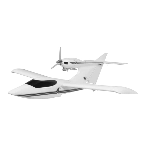
Wingspan: 71 in [1805mm]
Wing Area: 676 sq in [43.6 dm
Weight: 10.25 – 12.25 lb [4620 – 5555g]
Wing Loading: 35 – 41 oz/sq ft [106 – 127 g/dm
Length: 56 in [1410mm]
Radio: 5 or 6-channel with 7-9 servos
Engine: .60 cu in [10cc] two-stroke,
.70 – .91 cu in [11.5 – 15cc] four-stroke
Great Planes
®
Model Manufacturing Co. guarantees this kit to be free from defects in both material and workmanship at the date of purchase. This
warranty does not cover any component parts damaged by use or modification. In no case shall Great Planes' liability exceed the original cost of
the purchased kit. Further, Great Planes reserves the right to change or modify this warranty without notice.
In that Great Planes has no control over the final assembly or material used for final assembly, no liability shall be assumed nor accepted for any
damage resulting from the use by the user of the final user-assembled product. By the act of using the user-assembled product, the user accepts all
resulting liability.
If the buyer is not prepared to accept the liability associated with the use of this product, the buyer is advised to return this kit immediately
in new and unused condition to the place of purchase.
To make a warranty claim send the defective part or item to Hobby Services at the address below:
Include a letter stating your name, return shipping address, as much contact information as possible (daytime telephone number, fax number, e-mail
address), a detailed description of the problem and a photocopy of the purchase receipt. Upon receipt of the package the problem will be evaluated as
quickly as possible.
READ THROUGH THIS MANUAL BEFORE STARTING
CONSTRUCTION.
INSTRUCTIONS AND WARNINGS CONCERNING
THE ASSEMBLY AND USE OF THIS MODEL.
Entire Contents © Copyright 2005
INSTRUCTION MANUAL
2
]
2
]
3002 N. Apollo Dr., Suite 1
IT
CONTAINS
WARRANTY
Hobby Services
Champaign, IL 61822
USA
IMPORTANT
Champaign, IL
(217) 398-8970, Ext. 5
airsupport@greatplanes.com
GPMZ0242 for GPMA1360 V1.0
Advertisement
Table of Contents

Related Manuals for GREAT PLANES Seawind ARF


Summary of Contents for GREAT PLANES Seawind ARF
-
Page 1: Instruction Manual
Upon receipt of the package the problem will be evaluated as quickly as possible. READ THROUGH THIS MANUAL BEFORE STARTING CONSTRUCTION. CONTAINS IMPORTANT INSTRUCTIONS AND WARNINGS CONCERNING Champaign, IL THE ASSEMBLY AND USE OF THIS MODEL. (217) 398-8970, Ext. 5 airsupport@greatplanes.com Entire Contents © Copyright 2005 GPMZ0242 for GPMA1360 V1.0... -
Page 2: Table Of Contents
Many hours of development and test flying have gone into Covering Tools ..............4 Optional Supplies & Tools ..........4 the Great Planes Seawind ARF to create an easy to build IMPORTANT BUILDING NOTES...........4 and fly amphibious plane. Whether you’re an experienced ORDERING REPLACEMENT PARTS ........5... -
Page 3: Scale Competition
Radio Equipment 3. You must take time to build straight, true and strong. For the basic setup to fly off of water the Seawind ARF requires: 4. You must use an R/C radio system that is in first-class condition, and a correctly sized engine and components ❏... -
Page 4: Engine Recommendations
Optional Retracts Optional Supplies & Tools The Seawind ARF can be built three ways. If it will be flown off Here is a list of optional tools mentioned in the manual that of water, no landing gear is required. If the Seawind ARF will be will help you build the Seawind ARF. -
Page 5: Ordering Replacement Parts
4.8 mm 18" = 457.2 mm 1/4" 6.4 mm 21" = 533.4 mm Replacement parts for the Great Planes Seawind ARF are 3/8" 9.5 mm 24" = 609.6 mm available using the order numbers in the Replacement Parts 1/2" 12.7 mm 30"... -
Page 6: Kit Inspection
Kit Contents list. Great Planes Product Support 3002 N. Apollo Drive, Suite 1 Champaign, IL 61822 Telephone: (217) 398-8970, ext. 5 Fax: (217) 398-7721 E-mail: airsupport@greatplanes.com Parts Layout Kit Contents Fuselage 11. Aileron & Flap Servo Covers 21. Main Wheels (3) Rudder 12. -
Page 7: Assemble The Airplane Stand
ASSEMBLE THE AIRPLANE STAND ❏ 4. Use a Great Planes Dead Center hole locator to mark ™ on the engine mount the four engine mounting holes. ❏ 5. Remove the engine mount and use a drill press, if you ❏ 1. -
Page 8: Install The Fuel Tank
❏ ❏ 2. Drill a 3/16" [4.8mm] hole through the front of the firewall. 2. Carefully bend one of the long tubes so that it will angle Roughen the outer pushrod with sandpaper. Insert the outer up toward the top of the fuel tank when inserted. Do not kink pushrod tube through the firewall and the former so that it the tube. -
Page 9: Install The Throttle Servo
Install the Throttle Servo ❏ 6. Insert the throttle pushrod in the pushrod tube. Insert the Z-Bend in the throttle servo horn. Position the throttle servo in the fuel tank compartment. ❏ 1. Position the Micro servo with the top of the servo case flush and centered with the edge of the throttle servo tray. -
Page 10: Install The Cowl
Adjust the ❏ cowl so that the spinner backplate aligns with the front of the 10. Install the spinner nut included with the Seawind ARF. cowl. Tape the cowl in position. Position the spinner over the propeller and use the included socket-head bolt to attach the spinner to the spinner nut. -
Page 11: Landing Gear Installation Or Not
plywood plate with epoxy, thinned with denatured alcohol, to prevent the wood from soaking up water. LANDING GEAR INSTALLATION OR NOT ❏ 4. Use sandpaper to roughen the inside of the nose gear opening where the cover plate will be glued. Clean the area with denatured alcohol. - Page 12 ❏ 6. Drill a 3/32" [2.4mm] hole through the aft edge of the nose wheel recess, 1" [25.4mm] from the bottom of the fuselage.You will need to remove the nose gear to allow room for the drill. While the nose gear is removed, apply a couple of drops of thin CA to each of the screw mounting holes to harden the wood, before remounting the nose gear.
- Page 13 ❏ ❏ 14. Position the landing gear block in the metal main landing gear mount so that the landing gear wire goes through ❏ 10. Install a 5/32" [4mm] wheel collar and 6-32 [4mm] set the mount. Drill a 7/64" [2.7mm] pilot hole at each mounting screw on the nose gear wire, followed by one of the foam hole location and attach the landing gear block to the metal wheels and a second wheel collar and set screw.
-
Page 14: Retractable Landing Gear
Retractable Landing Gear ❏ 5. Attach the control valve to the plywood control valve mount. Attach the air line tubing to the control valve and glue the mount to the radio tray. ❏ 1. Drill 1/16" [1.6mm] pilot holes and mount the steering ❏... - Page 15 line tubing on the main retracts. Position the main retract in the wing so that the wheel is centered in the wheel well. Use a felt- tip pen to outline the mounting flanges of the main retracts. Use a sharp hobby knife to cut and remove balsa sheeting over the hardwood mounting rails.
-
Page 16: Install The Stabilizer
INSTALL THE STABILIZER ❏ 5. To keep the CA hinges centered in the control surfaces while installing them, insert a T-pin in the center of the hinge. Insert the hinges in the stabilizer and install the elevator. Remove the T-pins and adjust the control surface ❏... -
Page 17: Radio Installation
RADIO INSTALLATION ❏ 1. Install a 36" [914mm] servo extension on the elevator servo. Tie the end of the servo extension to the string and carefully pull the extension through the fuselage. Tape or heat- shrink the leads together. ❏ 2. -
Page 18: Finish The Wing
❏ 9. Connect 36" [914mm] servo extensions to the aileron be flying the Seawind ARF from water, we recommend that and flap servos. Use tape or heat-shrink to secure the you apply a bead of silicone sealant between the servo covers extension to the servo lead. -
Page 19: Finish The Radio Installation
FINISH THE RADIO INSTALLATION ❏ 2. Insert and glue the wing tip support in the tip rib of the left wing. ❏ 1. Insert the aluminum wing joiner in the fuselage. Space it evenly on both sides of the fuselage. ❏... -
Page 20: Finish The Fuselage
FINISH THE FUSELAGE ❏ 4. Install the receiver on/off switch on the left side of the radio tray. Wrap the receiver and receiver battery in foam and place them on the radio tray. If flying from the water, we recommend placing the receiver and battery in a plastic bag. ❏... -
Page 21: Get The Model Ready To Fly
TRANSMITTER ELEVATOR MOVES UP RUDDER MOVES RIGHT throw could make the model difficult to control, so remember, “more is not always better.” Note: If you will be flying the Seawind ARF off of water using 4-CHANNEL 4-CHANNEL TRANSMITTER TRANSMITTER the water rudder, once you have the rudder throws set, cut the... -
Page 22: Balance The Model (C.g.)
IMPORTANT: The stated C.G. is where your model must be balanced. The Seawind ARF does not have a C.G. range like most R/C planes. Do not move the C.G. forward or aft. Doing so will cause the plane to become difficult to control. -
Page 23: Balance The Propellers
Balance the Propellers ENGINE SAFETY PRECAUTIONS Failure to follow these safety precautions may result in severe injury to yourself and others. Keep all engine fuel in a safe place, away from high heat, sparks or flames, as fuel is very flammable. Do not smoke near the engine or fuel;... -
Page 24: General
General CHECK LIST 1) I will not fly my model aircraft in sanctioned events, air shows, or model flying demonstrations until it has been During the last few moments of preparation your mind may proven to be airworthy by having been previously, be elsewhere anticipating the excitement of the first flight. -
Page 25: Flying
Get used to how the model handles in water. As you use the do when flutter is detected is to slow the model water rudder to turn, you will notice that the Seawind ARF has immediately by reducing power, then land as soon as a tendency to dip a wing tip float. -
Page 26: Flight
While full throttle is usually desirable for takeoff, most models fly more smoothly at reduced speeds. Take it easy with the Seawind ARF for the first few flights, gradually getting acquainted with it as you gain confidence. Adjust the trims to maintain straight and level flight. After... - Page 27 Great Planes Ultimate Biplane ARF Great Planes Lancair ES .60 ARF The Ultimate Bipe 1.60 ARF’s polished look comes from The original Lancairs were high-performance homebuilts. precision-fitting parts made of select woods, surrounded by Great Planes’ version is high-performance too, but it’s also MonoKote covering and topped off with a painted fiberglass factory-built for ease.
- Page 28 BUILDING NOTES Kit Purchased Date: _______________________ Date Construction Finished: _________________ Where Purchased:_________________________ Finished Weight: __________________________ Date Construction Started: __________________ Date of First Flight: ________________________ FLIGHT LOG...
Need help?
Do you have a question about the Seawind ARF and is the answer not in the manual?
Questions and answers