
Related Manuals for Response SL5


Summary of Contents for Response SL5
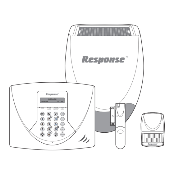
- Page 1 36 Zone Wireless Security System POWER ALARM ALARM MEM/ LINE STATUS MESSAGE STATUS ENTER Installation & Operating Manual...
-
Page 2: Part-Arming The System: Part-Arm
FOREWORD DEVICE RANGE devices in this wireless Alarm System are designed and manufactured to provide long reliable The quoted range of the system devices (see component service. The system is designed for ease of specification on rear cover) is measured in ideal installation using only conventional domestic tools. -
Page 3: Table Of Contents
CONTENTS KIT CONTENTS TESTING THE SYSTEM FACTORY SETTINGS INTRODUCTION AND OVERVIEW Reset Factory Settings Multiple Users User Access Code PROGRAMMING INSTRUCTIONS System Arming Navigating through the Programming Mode Menus Entry/Exit Delay Telephone Application Setup Zones User Setup Zone Lockout System Setup Quick Set Learn Remote Controls and Keypads Event Log... -
Page 4: Kit Contents
KIT CONTENTS The Alarm System should contain the following devices. 1 x Solar Siren 1 x Dummy Siren 1 x Control Panel 2 x PIR Movement Detectors 2 x Magnetic Door / Window Detectors Also included: Power Supply Adaptor RJ11-BT Telephone Connection Lead Siren and Dummy Siren Mounting Template Installation &... -
Page 5: Introduction And Overview
INTRODUCTION AND OVERVIEW MULTIPLE USERS The system allows for up to 6 Users, a Master and a Duress User to be configured. This allows the system Event Log to maintain a record of which users have armed and disarmed the system. Each user will have a different User Access Code. -
Page 6: Zones
The Entry-Delay for each zone may be configured for QUICK SET between 10 to 250 seconds or disabled completely. The system may be fully armed in 10 seconds using the quick set facility, overriding the programmed exit- Note: To conserve power and maximise battery life delay. -
Page 7: Latch Key
The jamming detection circuit will constantly scan for LATCH KEY jamming signals. However, it will also detect and When the system is Disarmed the Latch Key facility, could in extreme cases be triggered by radio signals if enabled, will call the first Latch Key phone number from other radio equipment within range operating on and replay the user message (recorded under latch the same frequency which would not interfere with... -
Page 8: Planning And Extending Your Alarm System
PLANNING AND EXTENDING YOUR ALARM SYSTEM Before attempting to install your Alarm System it is Typical Installation using only the detectors important to study your security requirements and supplied: plan your installation accordingly. Place the 1st Door / Window Detector (configured PIR Movement Detectors are used to protect the main on zone 1) on the front door. -
Page 9: Remote Control Unit
The system may be expanded with additional – User Access Codes 1-6 for the Control Panel detectors, Remote Controls and Keypads to provide should be changed to your own codes that even greater protection. However, the following rules only the relevant system user knows. should be followed: –... -
Page 10: Configuring The Remote Control
CONTROL PANEL CONFIGURING THE REMOTE CONTROL Remove the rear cover by undoing the small POSITIONING THE CONTROL PANEL screw on the rear of the Remote Control and keeping it safe for later. Insert the battery under the clip ensuring that Display Window terminal faces upwards away from the... -
Page 11: Installing And Configuring The Control Panel
Note: It is recommended that the telephone Do not drill the fixing holes with the Control connection lead is not extended beyond 10 metres Panel in position; as the resulting dust and before connecting to a telephone master or vibration may damage the Control Panel’s secondary outlet. -
Page 12: Linkinga Remote Control Or Remote Keypad To The Control Panel
Ensure that the Reset Jumper Link (P1) and the inserting the small RJ11 plug into socket marked External Tamper Switch Jumper Link (P51) are LINE located on the bottom edge of the Control set in the OFF position. Panel. If the cable supplied is not long enough to reach a suitable phone point then it will need Jumper Jumper... -
Page 13: Testing The Control Panel And Remote Control
The panel will now listen for a valid signal from a TESTING THE CONTROL PANEL AND new Remote Control or Keypad. REMOTE CONTROL The Panel will remain in Learn Mode for 30s. Press to put the ENTER If a valid signal is not received from a new User Access Code device within 30s it will automatically exit system into Test Mode. -
Page 14: Passive Infra-Red (Pir) Movement Detectors
PASSIVE INFRA-RED (PIR) MOVEMENT DETECTORS Detectors detect movement in a protected area 10 11 by detecting changes in infra-red radiation levels Detector Range (metres) caused for example when a person moves within or across the PIR’s detection pattern. If movement is detected an alarm will be triggered, (if the system is armed). -
Page 15: Installing And Configuring The Pir Detectors
INSTALLING AND CONFIGURING THE Fix the rear cover to the wall using the two PIR DETECTORS 18mm No.4 screws and 22mm wall plugs, (a 5mm hole will be required for the wall plugs). Do not over-tighten the screws as this may Rear Cover distort or damage the cover. -
Page 16: Linkinga Pir Detector To The Control Panel
On initial installation the detector should be To learn a new detector ID code and link it to configured into Walk Test ready for testing, the selected zone press (i.e. Pressing down SW1 for 2 seconds). The panel will now listen for a valid signal from a new detector to link to the zone. -
Page 17: Testinga Pir Detector With The Control Panel
TESTING A PIR DETECTOR WITH THE MAGNETIC DOOR / WINDOW CONTROL PANEL DETECTORS Ensure that the system is in Test Mode (see The Magnetic Door / Window Detector comprises of page 13). two parts; a Detector and a Magnet. They are Use the buttons to scroll through designed to be fitted to either doors or windows with... -
Page 18: Installing And Configuring The Door / Window Detectors
Do not fix the Detector onto or very close to Note: If mounting the device using the adhesive metalwork (i.e. radiators, water pipes, etc) as this pads, ensure that the mounting surfaces are could affect the radio range of the device. clean and dry before mounting. -
Page 19: Testing A Door / Window Detector Independently
Switch SW3 is used to enable / disable the TESTING A MAGNETIC DOOR / WINDOW internal / external wired magnetic contact. DETECTOR INDEPENDENTLY Remove battery cover to activate the tamper switch. As the button is released the LED indicator will 11mm Location of illuminate for approximately 1 second to show... -
Page 20: With The Control Panel
Activate the Tamper Switch on the MAG Note: If no signal is received by the Control Panel detector. within 10 minutes, the display will return to ‘Detector Walk Test’. Note: If the detector is already linked to the Open the door/window to remove the Magnet control panel on any other zone then the from the Detector. -
Page 21: External Solar Siren
EXTERNAL SOLAR SIREN The Siren is encapsulated within a tough Shadows cast by neighbouring walls, trees and roof polycarbonate housing that also provides full overhangs should also be avoided. If the Siren is protection against adverse weather conditions. to be mounted below the eaves, it should be positioned a distance of at least twice the depth of An LED indicator unit is built into the Siren to act the eaves overhang below the eaves. -
Page 22: Power-Up Of The Solar Siren
Siren Switch SW3 ALARM TIME Tamper ALARM TIME Switch ALARM SOUND ALARM SOUND Learn BEEP SOUND BEEP SOUND C.U. OR SIREN Learn C.U. OR SIREN Switch 7.5 Volt DC 9 Volt startup charging battery adaptor input 6 Volt 1.2Ah rechargeable Wall mounting plate battery switch 2 marked “AJ”... -
Page 23: Testing The Wireless Solar Siren
Scroll through the Test Mode menu using the Indicator/Learn LEDs will start flashing buttons until ‘Wirefree Siren together rapidly, (once every second). Service ON’ displayed and press ENTER After 10s the ‘Siren Stop’ signal will automatically The Siren will produce two short beeps followed be retransmitted by the Control Panel for the siren by one long beep. -
Page 24: Dummy Siren
DUMMY SIREN INSTALLATION Remove the two screws on the battery Drill four 6mm holes and fit the wall plugs. compartment cover on the rear of the Dummy Fit the two 30mm fixing screws in the top holes Siren and remove the cover. leaving approximately 9mm of the screw Insert the 4 batteries ensuring correct polarity protruding. -
Page 25: External Connections
Connections (using normally Contact Detectors can be hardwired to these closed contacts) terminals (by purchasing the Response Wired Door/Window Contact Accessory Pack (PW1). The contacts on zone 36 should be normally open. TERMINAL BLOCK DETAIL An alarm will be triggered when the contacts close. -
Page 26: Testing The System
TESTING THE SYSTEM The Control Panel has a built in test facility to enable you to test the system at any time. However it is recommended that the system is tested at Detector Walk Test Walk Test Waiting... press ENTER regular intervals not exceeding 3 months. - Page 27 DETECTOR TEST When the detector is triggered the Control Panel will beep to indicate that a signal has Before commencing testing please ensure that there been received and display the zone of the is no movement in any PIR protected area for at detector that was activated.
- Page 28 MAG Detector – Alarm Press to activate the wired siren for 5s. ENTER Zone X : MAG During the test the LCD will display: Alarm Siren ON for 5s Stop->ESC MAG Detector – Tamper Zone X : MAG Press to stop the test early. Tamper ALARM TEST –...
- Page 29 SPECTRA LIGHTING TESTS Service OFF Scroll through the menu until ‘Spectra Lighting Test’ Wait... displayed on the LCD. The siren will produce two short beeps followed Press to activate the linked Spectra lighting ENTER 1 second later by a single long beep. The Siren for 5s.
- Page 30 If no acknowledgment signal is received When the call is answered the recorded form the Alarm Monitoring Service the panel main alarm message only will be repeatedly will beep and the LCD will display: replayed for a minimum of 60s after which time the current replay cycle will be Remote Manager completed and the test will end.
-
Page 31: Factory Settings
FACTORY SETTINGS FACTORY SETTINGS USER CODE SETUP LATCH KEY SETUP Master User: 1234 Status: Users 1-6: Not programmed Selected User Setup: OFF (all users) Duress Code: Not programmed Phone Numbers: Not programmed SYSTEM SETUP MENU ANSWER PHONE SETUP Alarm Duration: 3 minutes Status: Entry/Exit Delay period:... -
Page 32: Programming Instructions
PROGRAMMING INSTRUCTIONS With the system in Standby (i.e. with the display USER SETUP MENU showing ‘DISARM READY’). Master User Access Code User 1 Access Code Press ENTER User 2 Access Code Master User Access Code User 3 Access Code Note: To get to Standby Mode simply press User 4 Access Code repeatedly until only the POWER LED is illuminated. -
Page 33: Telephone Application Setup
VOICE DIALLER SETUP MENU 1. USER SETUP Phone Numbers press ENTER Record Alarm Messages Similar Replay Alarm Messages 1.0 Master User 1.1 User 1 1.7 Duress for Users Code: xxxx Code: xxxx Code: xxxx press ENTER press ENTER press ENTER SPECTRA LIGHTING SETUP Enter new code Enter new code... -
Page 35: System Setup
SYSTEM SETUP Scroll through the Zone menu until option ‘2.1 Remotes’ displayed. The number of Remote Controls / Keypads The parameters in this menu allow the configuration of already linked will be shown, (e.g. if there are two general system parameters, such as Alarm Duration Remotes Controls and one Remote Keypad linked and control of any hardwired or output relay alarm the display will show... -
Page 36: Alarm Duration
Confirm the new device ID code by sending ALARM DURATION the Disarm signal from the same new Remote Controls the alarm duration of the wireless, internal Control or Remote Keypad within 15s as control panel and wired sirens in the event of an follows…... -
Page 37: Entry Delay Beeps
To change the setting press which cannot be de-activated unless the alarm ENTER duration is set to 0). Enter the required delay period (10 - 240s). Scroll through the system menu until ‘2.7 Wired Press to save new setting and exit, or ENTER Siren’... -
Page 38: Zone Lockout
ZONE LOCKOUT REMOTE PHONE ACCESS AND CONTROL Prevents a single zone from triggering an alarm enabled, this allows the system to be remotely more than 3 times before the system is disarmed. controlled via the telephone. (Zone lockout is effective on all zones except Default setting: OFF 24-HOUR-INTRUDER and FIRE zones which cannot be locked out). -
Page 39: Zone Setup
ZONE SETUP The parameters in this menu allow each zones specific function to be configured. PROGRAM MODE Code: enter Master User Access Code and press ENTER 3. ZONE SETUP press ENTER Enter Zone(1-36) press ENTER Following structure is repeated for each zone only for wired zones 33-36... -
Page 40: Learn Detector Code
LEARN DETECTOR CODE (zones 1-32 only). Note: If the detector is already linked to the control panel on any other zone Allows a wireless detectors ID code to be learnt and then the panel will produce a single long linked to the selected wireless zone. beep and the received signal from the 3.1 Znn: xxxxx detector will be ignored. - Page 41 NAME To change the setting press ENTER This enables a name to be allocated to the zone so it Scroll through the menu options, until the can be identified by its location. required setting is displayed. Available for all zones 1- 36. Only available for Press to save new setting and exit, or ENTER...
-
Page 42: Monitoring Setup
PART-ARM 2 Note: For the telephone dialler to operate This controls whether the zone is active when correctly with the Alarm Monitoring Service the Part-Arm 2 is armed. ‘Dialler Mode’ (see System Setup) must be correctly set and programmed. Default setting: OFF (all zones) Scroll through the Zone menu until ‘3.6 Zxx Part-Arm 2’... -
Page 43: Voice Dialler
Press to move the cursor right. Notes: Press to delete the number under To enter code B, press the cursor. To enter code C, press Press (and hold) to erase the entire To enter code D, press number. To enter code E, press Press to save and exit, or To enter code F, press... -
Page 45: Latch Key Setup
LATCH KEY SETUP STATUS This controls which users the Latch Key facility will The parameters in this menu configures which operate with. users the Latch Key feature operates with and the telephone numbers that the system dials when the Default setting: OFF Latch Key is activated. - Page 46 After configuring required users press to return Notes: to the top level Latch Key menu. Press to insert a 3.5 seconds pause in User Status the dialling sequence. Scroll through the system menu until ‘User x Press to move the cursor left. Status’...
-
Page 47: Friedland Spectra Plus Lighting Setup
FRIEDLAND SPECTRA PLUS LIGHTING SETUP PROGRAM MODE Code: enter Master User Access Code and press ENTER 7. SPECTRA LIGHTING SETUP press ENTER 7.1 Lamp On Time 7.2 Lamp On Time 7.3 Stop Time 7.4 Start Time xx minutes xxxxxxxxxxxxxx HH:MM HH:MM press ENTER press ENTER... -
Page 48: Operating Instructions
OPERATING INSTRUCTIONS When leaving the premises, the system must be Armed. ARMING THE SYSTEM However, before doing so, check that all windows are The system can be set in FULL ARM mode using closed and locked, all protected doors are closed and either the Remote Control or the Control Panel as PIR Detectors are not obstructed. -
Page 49: Disarming The System With The Duress Code
time a Tamper or PA switch is triggered and If the system has been triggered the ‘ALARM each time a detector on an enabled zone is MEM’ LED will flash and the panel will beep triggered when the panel is armed. every 10 seconds. -
Page 50: Latch Key
LATCH KEY DEVICE TAMPER the Latch Key function is enabled and the The Tamper zone operates on a 24 hour basis. system is disarmed by a user that is enabled for (i.e. Receipt of a Tamper signal form any device Latch Key then…... -
Page 51: Remote Phone Access And Control
To stop the LED flashing press or access the User Event Messages: Event Log to read the event message. User x User x Disarm To read the event log press from Standby. User x PartArm 1 to manually scroll through the User x PartArm 2 events. -
Page 52: Monitoring
Double Dial-In for Operation with an External MONITORING (OPTIONAL) Answer Phone: REMOTE MANAGER the Remote Access and Control feature is to be Refer to Remote Manager diagram on page 53. used and the system is operating in conjunction with an external Answer Phone then an alarm occurs and the Remote Manager dialler is enabled…... -
Page 53: Voice Dialler
If a further zone 1 alarm event occurs after more than 10 minutes then this event will be transmitted to the AMS. System Zn 1 Zn 1 Zn 2 Zn 1 Armed Alarm Alarm Alarm Alarm event event event event Initial Zone 1 2nd Zone 1 Initial Zone 2... -
Page 54: Siren Service / Operating Mode
The dialler sequence can be stopped early by either… Service Mode: The siren will produce two short beeps followed 1 second later by a single long numbers have been dialled three times beep. The Siren LEDs will flash together in The system is disarmed conjunction with the beeps. - Page 55 Movement Detector: Under low battery conditions the LED behind the detector lens will flash when movement is detected to indicate that the battery needs to be replaced. Under normal battery conditions the LED does not illuminate unless the PIR Detector is in Walk Test mode.
-
Page 56: Maintenance
MAINTENANCE during this period, provided they are kept charged. The batteries will be damaged if they are stored in Your Alarm System requires very little maintenance. a discharged state for long periods. However, a few simple tasks will ensure its continued reliability and operation. -
Page 57: Alarm Record
ALARM RECORD Complete the following information during installation for future reference, when adding to your system and to assist trouble shooting. Detector Entry Part- Part- Zone Location Type Chime Type(s) Delay Arm 1 Arm 2... - Page 58 You may make a note of your System information below. Remote Manager Phone Numbers (Optional) Phone No. 1: Phone No. 2: System ID No: Voice Dialler Phone Numbers Phone No. 1: Phone No. 2: Phone No. 3: Phone No. 4: Latch Key Phone Numbers Phone No.
-
Page 59: Trouble Shooting
TROUBLE SHOOTING Symptom / Recommendation Control Unit not working - Power LED OFF Siren and Indicator LEDs operating but no or flashing. alarm at Control Panel. 1. Mains power failure - check if other electrical Siren’s Tamper switch activated. Check security circuits are operable. - Page 60 LED on Remote Control not illuminating, or PIR Detector LED flashes on detection of is dim when unit is operated. movement, (device in normal operation mode). Ensure battery is fitted with correct polarity. 1. PIR still in Walk Test Mode for fixed 5 minutes after the PCB button was activated.
- Page 61 LED on Door / Window Detector illuminating Voice-Dialler Not Responding to Alarm. when door or window is opened. Telephone line not connected or faulty - check Low battery - replace batteries. phone line with another phone. Incorrect phone numbers programmed. Control Unit Not Contacting Remote 3.
-
Page 62: Extending Your Alarm System
If an item develops a fault, the product must be returned to the point of sale with: 1. Proof of purchase. 2. A full description of the fault. 3. All relevant batteries (disconnected). Response is a trademark of Novar ED&S. - Page 63 NOTES...
-
Page 64: Component Specification
COMPONENT SPECIFICATION External Solar Siren Control Panel Remote Control (Optional) POWER ALARM ALARM MEM/ LINE STATUS MESSAGE STATUS ENTER operating frequency: 868MHz operating frequency: 868MHz operating frequency: 868MHz Range: 80 metre max. Range: 125 metre max. Sealed lead acid battery 6V /1.2Ahr Personal Attack (PA) switch Battery back-up Solar...
Need help?
Do you have a question about the SL5 and is the answer not in the manual?
Questions and answers
I have a Response wireless security system SL5. It is working but how to I access the main menu to adjust the time please?
To adjust the time on a Response wireless security system SL5, scroll through the system menu until ‘2.11 Time’ (and the current setting) is displayed. Then, press ENTER, enter the new time in the "hh:mm" format using the 24-hour clock, and press ENTER to save.
This answer is automatically generated
HI My alarm mem/message is flashing red on the console and beeping. What is it telling me?
A flashing red alarm message and beeping on the Response SL5 console indicate that an alarm has occurred. The 'ALARM MEM' LED will flash, and the panel will beep every few seconds to signal this.
This answer is automatically generated