
Related Manuals for Fischer Panda 4000s PMS SCB


Summary of Contents for Fischer Panda 4000s PMS SCB
- Page 1 Manual Description of the generator and operation manual Marine Generator Panda 4000s PMS SCB Panda 4000s PMS FCB 230 V - 50 Hz / 3,8 kW Super silent technology Fischer Panda GmbH...
-
Page 2: Current Revison Status
Current Revison Status Document Actual: Panda_4000s_PMS_SCB_FCB_eng.R02_31.7.09 Replace: Panda_4000s PMS_SCB_eng.R01 Revision Page Panda 4000s FCB added Copyright Duplication and change of the manual is permitted only with consultation with the manufacturer! Fischer Panda GmbH, 33104 Paderborn, reserves all rights regarding text and graphics. Details are given to the best of our knowledge. -
Page 3: Table Of Contents
Table of contents Current Revison Status......................2 Safety first symbols ....................... 6 Tools ............................9 Safety instructions - Safety first! ..................11 5 Safety steps to follow if someone is the victim of electrical shock ......19 WHEN AN ADULT STOPS BREATHING................20 The Panda Generator.................... - Page 4 Table of contents B.3.5 Installation below waterline ....................62 B.3.6 Raw water single circuit cooling system ................65 B.3.7 Ventilating at the first filling of the Fresh water cooling circuit - FCB only ......66 B.4 Watercooled Exhaust System ..................67 B.4.1 Installation of the standard exhaust system ...............
- Page 5 Table of contents D.4.2 Troubleshooting Table ....................... 96 Tables..........................97 Troubleshooting ......................97 Technical Data Engine ....................101 E.2.1 Technical Data Generator 4000s SCB + FCB ..............102 Engine oil ........................103 Coolant .......................... 104 Capsule Measurements 4000s ..................105 Remote Control Panel P4 Control ................
- Page 6 Intentionally Blank Page 4 Panda_4000s_PMS_SCB_FCB_eng.R02 - Table of contents 31.7.09...
- Page 7 since since since since since 1977 1978 1988 1988 1988 Icemaster GmbH Fischer Marine Conclusion Fischer - 100 % water cooled Panda Vehicle Generators Icemaster GmbH Panda generators Generators Fischer Panda FISCHER GENERATORS have been manufactured since 1978 and are a well-known brand for first class diesel generators with especially effective sound-insulation.
-
Page 8: Safety First Symbols
Safety first symbols These symbols are used throughout this manual and on labels on the machine itself to warn of the possibility of per- sonal injury. Read these instructions carefully. It is essential that you read the instructions and safety regulations before you attempt to assemble or use unit. - Page 9 Danger warning: Automatic start. generator can be started by an external signal Danger warning: High voltage / danger by electricity - Danger for life Danger warning: Danger for life and/or equipment Danger warning: Harmfull if accumulate Danger warning: Electric shock Danger warning: Keep hand and body away from rotating parts Danger warning: Risk of explosion Danger warning: Hot surface...
- Page 10 Danger warning: Danger carrosive material - contermination of persons possible Instruction: Wear personal protective equipment (PPE) Instruction: Read the manual instructions Instruction: Wear protective glasses Instruction: Wear safety gloves Instruction: Be mindful of enviroment and the ecology...
-
Page 11: Tools
Tools This symbols are used throughout this manual to show which tool must be used at maintenance or installation. Spanners X = required size Hook wrench for oil filter Screw driver, for slotted head screws and for recessed head screws Multimeter, multimeter with capacitor measuring Socket wrench set Hexagon wrench keys... - Page 12 Manufacturer declaration in accordance with the machine guideline 98/37/EG Manufacturer declaration in accordance with the machine guideline 98/37/EG The generator has been developed in such a way, that all assembly groups correspond to the CE guidelines. If machine guideline 98/37/EG is applied, then it is forbidden to start the generator, until it has been ascertained that the system into which the generator is to be integrated, also corresponds to the machine guideline regulation 98/37/ EG.
-
Page 13: Safety Instructions - Safety First
Safety instructions - Safety first! Safe operation Careful operation is your best assurance against an accident. Read and understand this manual carefully before operating the engine. All operators, no matter how much experience they may have, should read this and other related manuals befor operating the generator or any equipment atta- ched to it. - Page 14 Safe handling of fuel and lubricants - Keep away from fire Always stop the generator befor refueling and/or lubrivating. Do not smoke or allow flames or sparks in your work area. Fuel is extremely flammable and explosive under certain conditions. Refuel at a well ventilated and open place.
- Page 15 Cautions against burns and battery explosion To avoid burns, be cautious of hot components, e.g. muffler, muffler cover, radiator, hoses, engine body, coolants, engine oil, ect. during operation and after the engine has been shut down. Coo- lant system can be under pressure, Open the coolant system only, when the generator is colled down.
-
Page 16: Warning And Caution Labels
Conducting safety checks and maintenance Disconnect the battery from the generator before conducting service. Put a „DO NOT OPERATE“ tag on the remote control panel to avoid accidental starting. Disconnect any automatic starter device, e.g. battery monitor to prevent automatic starting. To avoid sparks from an accidental short circuit always disconnect the battery´s ground cable (-) first and connect it last. - Page 17 Safety Instructions concerning operating the generator The electrical installations may only be carried out by trained and qualified personnel! The generator must not be taken into use with the cover removed. If the generator is being installed without a sound insulation capsule, then make sure, that all rotating parts (belt-pulley, belts etc) are covered and protected so that there is no dan- ger to life and body! If a sound insulation covering will be produced at the place of installation, then well-placed...
- Page 18 Safety Instructions concerning operating the generator Safety Instructions concerning the capacitors Capacitors are required to run the generator. These have two varying functions: A) The working capacitors B) The (Booster) capacitors Both Groups are located in a separate AC-Control box. Capacitors are electrical stores.
- Page 19 Attention !! Check before installation if the starter battery voltage correspond with the generator start system. f.e. 12V starter battery for 12V start system f.e. 24V starter battery for 24V start system...
- Page 20 Intentionally Blank...
-
Page 21: Safety Steps To Follow If Someone Is The Victim Of Electrical Shock
5 Safety steps to follow if someone is the victim of electrical shock Do not try to pull or grab the individual. Send for help as soon as possible. If possible, turn off the electrical power. If you cannot turn off the electrical power, pull, push, or lift the person to safety using a wooden pole, rope, or some nonconductive material. -
Page 22: When An Adult Stops Breathing
WHEN AN ADULT STOPS BREATHING WARNING DO NOT attempt to perform the rescue breathing techniques provided on this page, unless certified. Performance of these techniques by uncertified personnel could result in further injury or death to the victim. Does the Person Respond? Shout, "Help!"... -
Page 23: The Panda Generator
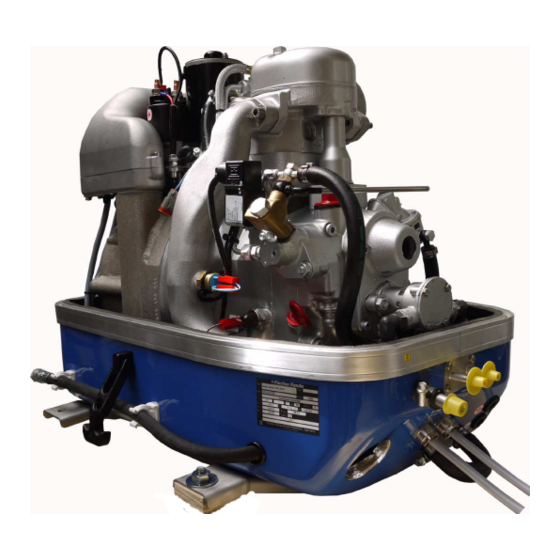
The Panda Generator A. The Panda Generator A.1 Type plate at the Generator Fig. A.1-1: Type plate at the generator - Picture shows 4000s SCB Fig. A.1-2: Discription type plate Panda_4000s_PMS_SCB_FCB_eng.R02 - Chapter A: The Panda Generator Page 21... -
Page 24: Description Of The Generator 4000S Scb Pms
The Panda Generator A.2 Description of the Generator 4000s SCB PMS A.2.1 Right Side View 4000s SCB PMS 01) Cylinder head 09) Combustian air intake 02) Fuel filter 10) Cooling water out at winding 03) Mechanical fuel pump 11) Cooling water in at engine 04) Speed adjust lever 12) Cooling water bypass from winding out to engine out 05) Raw water pump... -
Page 25: Left Side View 4000S Scb Pms
The Panda Generator A.2.2 Left Side View 4000s SCB PMS 01) Starter motor 10) Oil dipstick 02) Solenoid switch for starter motor 11) Oil pressure switch 03) Generator power terminal box and airfilter housing 12) Thermo switch exhaust elbow 04) Circuit breaker 015A 13) Fuel solenoid valve 05) Plug for optional electrical fuel pump 14) Fuel filter... -
Page 26: Front View 4000S Scb Pms
The Panda Generator A.2.3 Front View 4000s SCB PMS 01) Cylinder head 10) Cable for control panel 02) Fuel solenoid valve 11) Connection hose for cooling circle ventilation valve 03) Ventilation screw solenoid valve 12) Passage for battery cable (-) 04) Fuel filter 13) Passage for battery cable (+) 05) Water cooled exhaust elbow... -
Page 27: Back View 4000S Scb Pms
The Panda Generator A.2.4 Back View 4000s SCB PMS 01) Starter motor 05) Air inlet 02) Generator power terminal box and airfilter housing 06) Oil drain hose 03) Front plate 07) Air filter holder 04) Ball bearing Fig. A.2.4-1: Back view Panda_4000s_PMS_SCB_FCB_eng.R02 - Chapter A: The Panda Generator Page 25... -
Page 28: View From Above 4000S Scb Pms
The Panda Generator A.2.5 View from above 4000s SCB PMS 01) Generator power terminal box and airfilter housing 08) Air suction hose 02) Solenoid switch for starter motor 09) Starter motor 03) Injection nozzle 10) Cooling water connection block 04) Water-cooled exhaust elbow 11) Thermo-switch cylinder head 05) Cylinder head 12) Fuel pump... -
Page 29: Description Of The Generator 4000S Fcb Pms
The Panda Generator A.3 Description of the Generator 4000s FCB PMS A.3.1 Right Side View 4000s FCB PMS 01) Cylinder head 08) Generator housing with coil 02) Fuel Filter 09) Combustian air intake 03) Mechanical fuel pump 10) Cooling water out at winding 04) Speed adjust lever 11) Heat exchanger 05) Fresh water pump... -
Page 30: Left Side View 4000S Fcb Pms
The Panda Generator 4000s FCB PMS A.3.2 Left Side View 01) Starter motor 09) Raw water in 02) Solenoid switch for starter motor 10) Oil dipstick 03) Generator power terminal box and airfilter housing 11) Oil pressure switch 04) Circuit breaker 015A 12) Thermo switch exhaust elbow 05) Plug for optional electrical fuel pump 13) Fuel solenoid valve... -
Page 31: Front View 4000S 4000S Fcb Pms
The Panda Generator 4000s FCB PMS A.3.3 Front View 4000s 01) Cylinder head 11) Cable for control panel 02) Fuel solenoid valve 12) Connection hose for cooling circle ventilation valve 03) Ventilation screw solenoid valve 13) Connection hose for external expension tank 04) Fuel filter 14) Passage for battery cable (-) AND (+) 05) Water cooled exhaust elbow... -
Page 32: Back View 4000S Fcb Pms
The Panda Generator 4000s FCB PMS A.3.4 Back View 01) Starter motor 05) Ball bearing 02) Generator power terminal box and airfilter housing 06) Air inlet 03) Air filter holder 07) Oil drain hose 04) Front plate Fig. A.3.4-1: Back view Page 30 Panda_4000s_PMS_SCB_FCB_eng.R02 - Chapter A: The Panda Generator 31.7.09... -
Page 33: View From Above 4000S Fcb Pms
The Panda Generator 4000s FCB PMS A.3.5 View from above 01) Generator power terminal box and airfilter housing 08) Air suction hose 02) Solenoid switch for starter motor 09) Starter motor 03) Injection nozzle 10) Cooling water connection block 04) Water-cooled exhaust elbow 11) Thermo-switch cylinder head 05) Cylinder head 12) Fuel pump... -
Page 34: Details Of Functional Units
The Panda Generator A.4 Details of Functional Units A.4.1 Remote Control Panel - see Remote Control Panel Datasheet Remote Control Panel The remote control panel is necessary to control the generator and to evaluate the motor/genera- tor properties. The generators will automatically cutout, if it does not run as required. The genera- tor may not be run without the remote control panel. -
Page 35: Components Of Cooling System (Raw Water) 4000S Scb
The Panda Generator A.4.2 Components of Cooling System (Raw water) 4000s SCB One circle system Exhaust and water outlet Water inlet 01) Cooling water in (raw water in) 07) Water connection block (cooling water out at 02) Raw water pump engine) 03) Connection hose for cooling circle ventilation valve 08) Water cooled exhaust elbow... - Page 36 The Panda Generator Raw water intake The diagram shows the supply pipes for the generator. The connection neck for the raw water connection is shown on the right hand side. The cross-section of the intake pipe should be nominally larger than the generator connection.
- Page 37 The Panda Generator Generator housing The water in is at the bottem of the Gene- rator housing. The water out is at the top of the generator. Fig. A.4.2-4: Generator housing Engine in Fig. A.4.2-5: Engine in Engine out (water connection block) Fig.
- Page 38 The Panda Generator Injection Port Raw Water The point of introduction (point of injec- ting) for the raw water cooled exhaust system of the marine generator is at the exhaust elbow. The exhaust elbow must be checked regularly carefully for traces by corrosion.
-
Page 39: Components Of Cooling System (Raw Water + Fresh Water) 4000S Fcb
The Panda Generator A.4.3 Components of Cooling System (Raw water + Fresh water) 4000s Two circle system Sea water inlet Up intake Exhaust with sea water outlet Stilling Air offtake to stilling basin's up intake basin Fresh water offtake to stilling basin's down intake 01) Cooling water in (raw water in) 07) Water connection block (cooling water out at 02) Raw water pump... -
Page 40: A.4.3.1Components Of Cooling System (Raw Water) 4000S Fcb
The Panda Generator A.4.3.1Components of Cooling System (Raw water) 4000s FCB Raw water intake The diagram shows the supply pipes for the generator. The connection neck for the raw water connection is shown on the right hand side. The cross-section of the intake pipe should be nominally larger than the generator connection. - Page 41 The Panda Generator Ventilation valve An appropriate ventilation line must be installed, if the danger exists that the generator can stand only briefly by move- ments of the ship below the waterlinie. For this generally a hose line is prepared at the generator housing.
-
Page 42: A.4.3.2Components Of Cooling System (Fresh Water)4000S Fcb
The Panda Generator Raw water output The raw water discharges together with the exhaust. Fig. A.4.3-6: Raw water output A.4.3.2Components of Cooling System (Fresh water)4000s FCB Connection external expansion tank The external expansion tank is connected by two hose connections. Fig. - Page 43 The Panda Generator Generator housing The water in is at the bottem of the Gene- rator housing. The water out is at the top of the generator. Fig. A.4.3-3: Generator housing Engine in Fig. A.4.3-4: Engine in Engine out (water connection block) Fig.
- Page 44 The Panda Generator Heat exchanger The heat exchanger separates the inter- nal fresh water cooling circle from the raw water cooling circle, so that the generator components do not have contact with the raw water circulation system. The raw water is fed directly to the exhaust con- nection piece at the heat exchanger out- let.
-
Page 45: Components Of Conbustion Air 4000S Scb + 4000S Fcb
The Panda Generator A.4.4 Components of conbustion air 4000s SCB + 4000s FCB Air inlet Exhaust 01) Air inlet 04) Air in at engine 02) Generator housing with coil 05) Water cooled exhaust elbow 03) Generator power terminal box and airfilter housing 31.7.09 Panda_4000s_PMS_SCB_FCB_eng.R02 - Chapter A: The Panda Generator Page 43... - Page 46 The Panda Generator Combustion air intake The sound insulated capsule for the marine generator is normally provided at the side surface with drillings, through which the combustion air can influx. Fig. A.4.4-1: Combustion air intake Cooling of the generator housing The cumbustian air is pre-warmed in the generator housing.
- Page 47 The Panda Generator Exhaust elbow At the back of the engine is the water-coo- led exhaust elbow. Fig. A.4.4-4: Exhaust elbow Exhaust outlet Connect the exhaust pipe with the water lock. Fig. A.4.4-5: Exhaust output Panda_4000s_PMS_SCB_FCB_eng.R02 - Chapter A: The Panda Generator Page 45...
-
Page 48: Components Of The Fuel System 4000S Scb + 4000S Fcb
The Panda Generator A.4.5 Components of the Fuel System 4000s SCB + 4000s FCB Fuel outlet Fuel inlet 01) Fuel in 04) Injection nozzle at engine 02) Fuel pump 05) Fuel out (Fuel return line) 03) Fuel stop solonoid Page 46 Panda_4000s_PMS_SCB_FCB_eng.R02 - Chapter A: The Panda Generator... - Page 49 The Panda Generator Connecting pieces for the fuel pipes 1. Fuel IN 2. Fuel OUT Fig. A.4.5-1: Fuel connections Fuel pump Fig. A.4.5-2: External fuel pump Fuel solenoid valve The fuel solenoid valve opens automati- cally if „START“ is pressed on the remote control panel.
-
Page 50: Components Of Electrical System 4000S Scb + 4000S Fcb
The Panda Generator Injection nozzle at engine Fig. A.4.5-4: Injection nozzle at engine A.4.6 Components of Electrical System 4000s SCB + 4000s FCB Connection starter battery 1. Passage for starter battery cable (plus) 2. Passage for starter battery cable (minus) During the connection to the starter bat- tery it must always be ensured that the contact is perfectly guaranteed. - Page 51 The Panda Generator Electrical connections for control and load At the front of the generator are also all remaining cables for the electrical connec- tions depending upon type. 1. Remote control panel 2. AC out Fig. A.4.6-2: Load Fuel Pump connection point An optional electrical fuel pump can be connected at the left side of the generator.
- Page 52 The Panda Generator Generator power terminal box Above the winding housing is the genera- tor power terminal box. In this box, the electrical connection points for the AC generator are blocked. Here is also the bridge for the protective grounding of the generator. The cover may only be removed, if it is guaranteed that the generator cannot be inadvertently started.
-
Page 53: Sensors And Switches For Operation Surveillance
The Panda Generator Capacitor 01. The capacitor can be located in the power terminal box cover Fig. A.4.6-8: Terminal block A.4.7 Sensors and Switches for Operation Surveillance Thermo-switch at cylinder head The thermo-switch at the cylinder head serves monitor generator temperature. -
Page 54: Components Of Oil Circuit 4000S Scb + 4000S Fcb
The Panda Generator Thermo-switch in the generator coil 1. Generator coil 2. Thermo-switch 3. Housing Two thermo switches are located inside the winding to protect the generator coil, which for safety reasonsare installed inde- pendently in parallel. Fig. A.4.7-3: Thermo-switch coil Oil pressure switch In order to be able to monitor the lubrica- ting oil system, an oil pressure switch is... - Page 55 The Panda Generator Oil dipstick At the dipstick the permissible level is indi- cated by the markings "maximum" and "minimum". The engine oil should be never filled beyond the maximum. Fig. A.4.8-2: Engine oil dipstick Engine oil strainer The oil strainer is normally maintenance- free;...
-
Page 56: Operation Manual
The Panda Generator A.5 Operation manual A.5.1 Preliminary remarks Advices regarding Starter Battery Fischer Panda recommends to use a normal starter battery. If the generator is required for extreme winter conditions, the starter battery capacity should be doubled. It is recommended to regularly charge the starter battery by a suitable battery-charging device (i.e. -
Page 57: Starting Generator - See Remote Control Panel Datasheet
The Panda Generator A.5.2 Daily routine checks before starting The mounting screws must be checked regularly to ensure the generator is safe. A visual check of these screws must be made, when the oil level is checked. 8. Switch the land electricity/Generator switch to zero before starting or switching off all load. The generator should only be started when all load have been switched off. - Page 58 The Panda Generator Page 56 Panda_4000s_PMS_SCB_FCB_eng.R02 - Chapter A: The Panda Generator...
-
Page 59: Installation Instructions
Installation Instructions B. Installation Instructions B.1 Placement B.1.1 Placement and Basemount Since Panda generators have extremely compact dimensions they can be installed in tight locati- ons, attempts are sometimes made to install them in almost inaccessible places. Please consider that even almost maintenance-free machinery must still remain accessible at least at the front (drive belt, water pump) and the service-side (actuator, dipstick). -
Page 60: Generator Connections - Scheme
Installation Instructions B.2 Generator Connections - Scheme All electrical wires are connected tightly to the motor and the generator. This is also the case for fuel lines and cooling water lines. The electrial connections must be carried out according to the respective valid regulati- ons. -
Page 61: Cooling System Installation - Raw Water
Installation Instructions Exhaust connection 01. Connect your exhaust hose direct to the water cooled exhaust elbow. Use both clamps delivered with the gene- rator. Fig. B.2-3: Connections B.3 Cooling System Installation - Raw water B.3.1 General References The genset should have its own sea water (coolant water) inlet and should not be connected to any other engine systems. -
Page 62: Installation Of The Thru-Vessel Fitting In Yachts
Installation Instructions B.3.2 Installation of the thru-vessel fitting in Yachts It is good practice for yachts to use a hull inlet fit- ting with an integrated strainer. The thru-vessel fitting (raw water intake) is often mounted against the sailing direction to induce more water intake for cooling. -
Page 63: Installation Above Waterline
Installation Instructions B.3.4 Installation above waterline The Panda is equipped with a direct drive water intake pump mounted directly on the motor. Since the intake pump is an impeller pump there are wearing parts which are likely to require replacement after some time. Ensure that the genset is installed such that the intake pump can be easily accessed. -
Page 64: Installation Below Waterline
Installation Instructions Raw water impeller pump Water cock Freshwater pump Raw water inlet Water-cooled exhaust elbow Expansion tank Cooling water connection block 10. Vent valve Heat exchanger 11. Oil cooler Raw water filter 12. Reducer Fig. B.3.4-2: Installation example over the waterline FCB version B.3.5 Installation below waterline If the generator can not be attached at least 600mm over the waterline, a vent valve must be installed into the raw water line. - Page 65 Installation Instructions Cut the hose for the external vent valve... Fig. B.3.5-1: Connection external ventilation valve ..and bent it upwards. Both hose ends must be led out outside of the sound cover to one point, if possible 600mm over the waterline in the midship line.
- Page 66 Installation Instructions Raw water impeller pump Water cock Freshwater pump Raw water inlet Water-cooled exhaust elbow Expansion tank Cooling water connection block 10. Vent valve Heat exchanger 11. Oil cooler Raw water filter 12. Reducer Fig. B.3.5-4: Installation example under the waterline FCB Page 64 Panda_4000s_PMS_SCB_FCB_eng.R02 - Chapter B: Installation Instructions 31.7.09...
-
Page 67: Raw Water Single Circuit Cooling System
Installation Instructions B.3.6 Raw water single circuit cooling system 1. Vent valve 5. Raw water filter 2. Coolant connection bock 6. Sea cock 3. Exhaust elbow 7. Hull inlet 4. Raw water pump Fig. B.3.6-1: Installation example under the waterline SCB 31.7.09 Panda_4000s_PMS_SCB_FCB_eng.R02 - Chapter B: Installation Instructions Page 65... -
Page 68: Ventilating At The First Filling Of The Fresh Water Cooling Circuit - Fcb Only
Installation Instructions B.3.7 Ventilating at the first filling of the Fresh water cooling circuit - FCB only The Fresh water circle of the Panda 4000s FCB PMS is self venting while the electrical coolant pump is running. Make shure, that the generator is aligned horizontally to all sides. 1. -
Page 69: Watercooled Exhaust System
Installation Instructions B.4 Watercooled Exhaust System By injecting the outlet seawater into the exhaust manifold, the exhaust gases are cooled and the noise emissions from the exhaust system are reduced. B.4.1 Installation of the standard exhaust system The generator exhaust system must remain completely independent and separate from the exhaust system of any other unit(s) on board. -
Page 70: Exhaust / Water Separator
Installation Instructions B.4.2 Exhaust / water separator The exhaust/water separator In order to reduce the noise level of the generator unit to a minimum, an optional exhaust outlet muffler mounted next to the thru-hull fitting can be installed. Additionally there is component at Fischer Panda, which exercise both functions of a "exhaust goose neck", and the water separa- tion. -
Page 71: Installation Exhaust/Water Separator
Installation Instructions B.4.3 Installation exhaust/water separator If the exhaust/water separator was sufficiently highly installed, a goose neck is no longer neces- sary. The exhaust/water separator fulfills the same function. If the "Supersilent" exhaust system were installed correctly, the generator will not disturb your boat neighbour. The exhaust noise should be nearly inaudible. -
Page 72: Fuel System Installation
Installation Instructions B.5 Fuel System Installation B.5.1 General References Fuel filters (with water seperator) must be mounted outside the capsule in easily accessible pla- ces in the fuel lines between the tank intake fuel pump and the diesel motor's fuel pump. Generally forward and return fuel flow pipes must be mounted to the diesel tanks. -
Page 73: Connection Of The Fuel Lines At The Tank
Installation Instructions B.5.2 Connection of the fuel lines at the tank Lead the return fuel pipe connected to the day tank to the floor The return pipe connected to the tank must be dropped to the same depth as the suction pipe, the generfator is mounted higher than the tank, in order to prevent fuel running back into the tank after the motor has been switched off, which can lead to enormous problems if the generator swit- ched off for a long period. -
Page 74: Connection Of The 12V Starter Battery
Installation Instructions B.6.1 Connection of the 12V starter battery The positive (+) battery cable is connec- ted direcly to the solenoid switch of the starter. Attention: Use the prepared protective tube for the battery (+) cable. Fig. B.6.1-1: Connection starter battery plus cable Connection of the battery (-) Connect the battery (-) with the connec- tion point at the engine foot... -
Page 75: B.6.1.1Additional Information For Battery Connection
Installation Instructions All Panda generators are equipped with an independent 12V-DC starter motor. The connecting lines cross-section from the battery to the DC system should mea- sure 25mm². 1. Solenoid switch for starter motor 2. Starter motor Fig. B.6.1-4: Starter motor B.6.1.1Additional information for battery connection ATTENTION !!! Commissioning: Installation of battery lines. -
Page 76: Connection Of The Load
Installation Instructions Sample diagram for starterbattery installation B.6.2 Connection of the load Connection of the load Connect the load at the prepared cable 01. Cable for load Page 74 Panda_4000s_PMS_SCB_FCB_eng.R02 - Chapter B: Installation Instructions 31.7.09... -
Page 77: Connection Of The Remote Control Panel - See Remote Control Panel Datasheet
Installation Instructions B.6.3 Connection of the remote control panel - see remote control panel datasheet As standard a 7 core connection-cable, 7m long, is included in the supply. Cores are numbered from 1 to 7. The control cables are securely connected to the gen- set. -
Page 78: Generator Ac System-Installation
Installation Instructions B.7 Generator AC System-Installation ATTENTION! Before the electrical system is installed, READ the section “Safety instruc- tions - Safety first!” on page 11 of this manual FIRST! Be sure that all electrical installati- ons (including all safety systems) comply with all required regulations of the regional authorities. -
Page 79: Maintenance Instructions
Maintenance Instructions C. Maintenance Instructions C.1 General maintenance instructions C.1.1 Checks before starting • Oil level • Cooling system leaks • Visual check for any changes, leaks oil drain system, v-belt, cable connections, hose clips, air filter, fuel lines C.1.2 Hose elements and rubber formed component in the sound cover Check all hoses and hose connections for good condition. -
Page 80: Engine Oil Change
Maintenance Instructions C.2.1 Engine oil change Oil drain screw For the oil change an oil drain hose is lead through the sound cover. The oil can be discharged by opening the oil drain screw. For countering use a second wrench. Fig. - Page 81 Maintenance Instructions Open the oil filler neck After opening the cap of the oil filler neck the new oil is refilled. Please wait instant, before measure the oil level, the oil must set off in the sump. Fig. C.2.1-3: Oil fillerneck Oil dipstick With the help of the engine oil dipstick the oil level is to examined.
-
Page 82: Ventilating The Fuel System
Maintenance Instructions C.3 Ventilating the fuel system Normally, the fuel system is designed to bleed out air itself i.e. as soon as the electric starter motor starts operation the fuel pump starts working and the fuel system will be de-aerated after some time automatically. -
Page 83: Replace The Air Filter Element
Maintenance Instructions C.3.2 Exchange of the Fuel Filter Exchanging the filter, depending upon fuel contamination, should take place after 300 operational hours at the very least. The inlet must be clamped, before exchanging the filter. Remove the hoses from the used filter and fasten them to the new filter. -
Page 84: Draining The Coolant
Maintenance Instructions Pull the holder out to change the element. Fig. C.4-2: Air filter element If no change of the cooling water level can be determined, the generator is started for 5 minutes. Afterwards repeat the de-aeration two - three times. It is meaningful to repeat the de-aeration procedure also after some days again to guarantee that in the system remained bubbles are removed. -
Page 85: The Raw Water Circuit
Maintenance Instructions C.5 The raw water circuit C.5.1 Clean raw water filter The raw water filter should be released regularly from arrears. In each case the water cock must be closed before. It is mostly sufficient to beat the filter punnet. If water should seep through the cover of the raw water filter, this may be sealed in no case with adhesive or sealant. -
Page 86: Replace The Impeller
Maintenance Instructions C.5.3 Replace the impeller Close the raw water stop cock. Fig. C.5.3-1: Raw water stop cock Raw water pump on the front side of the genset. Fig. C.5.3-2: Raw water pump Remove the cover of the raw water pump by loosen the 4 wing screws from the hou- sing. - Page 87 Maintenance Instructions Mark the impeller, to make sure that these is used in the correct position at re-instal- lation. Pull to the impeller with a multigrip pliers of the wave. Fig. C.5.3-4: Impeller Check to the impeller for damage and replace it if necessary.
-
Page 88: Conservation At Longer Operation Interruption
Maintenance Instructions C.6 Conservation at longer operation interruption C.6.1 Measures on preparation of the winter storage 1. Rinse raw water circuit with an anti-freeze solution, even if this contains a corrosion protection means. The raw water inlet must be removed at the water cock. Over a hose connector the anti-freeze protection mixture is to be sucked in from a container. -
Page 89: Initiation At Spring
Maintenance Instructions C.6.1 Measures on preparation of the winter storage 15.Lubricate the spindle for the number of revolutions adjustment device with a special lubricant (Antiseize grease). 16.Check cooling water connection block at the generator housing on traces of corrosion and if necessary renew. - Page 90 Maintenance Instructions Page 88 Panda_4000s_PMS_SCB_FCB_eng.R02 - Chpater C: Maintenance Instructions 31.7.09...
-
Page 91: Generator Failure
Generator Failure D. Generator Failure D.1 Tools and measuring instruments In order to be able to manage disturbances while driving, following tools and measuring instruments should belong to the equipment on board: • Multimeter for voltage (AC), frequency and resistance •... -
Page 92: Monitoring The Generator Voltage
Generator Failure Overloading the Generator with Electric Motors With the operation of electric motors it must be considered that these take up a multiple of their rated output as starting current (six to tenfold). If the power of the generator for the engine is not sufficient, the voltage in the generator breaks down after switching on the engine. -
Page 93: Low Generator-Output Voltage
Generator Failure Re-connect the connections if the electrical supply lines in the AC-control box were also be dis- connected. The generator can’t be damaged by an overload because the winding is overload- and short-cir- cuit safety. But damages are possible in the periphery. Especially connected loads are endange- red because a lower voltage can damage them by order. -
Page 94: Checking The Capacitor
Generator Failure D.3.2 Checking the capacitor If the capacitors are to be checked, it is to be made certain that the capacitors will be discharged before touching. Already a visual check can give informa- tion on whether the capacitors are defec- tive: - Leaks dielectric? - did the capacitor became longer? -
Page 95: Checking The Generator Voltage
Generator Failure D.3.3 Checking the generator voltage In order to test, whether the fixed winding produces enough voltage, proceed in such a way: 1. Guarantee that the connection to the electrical system is interrupted. 2. Remove all conductions in the power terminal box of the generator. 3. -
Page 96: Checking The Coil(S) To Short-Circuit
Generator Failure D.3.5 Checking the coil(s) to short-circuit In order to check the coils for short-circuit, first all lines, which lead to the electrical system, must be interrupted. This happens on the power terminal box of the generator or, if available, in the electrical system junction box. -
Page 97: Starting Problems
Generator Failure D.4 Starting Problems D.4.1 Fuel Solenoid Valve The fuel solenoid valve is located in front of the injection pump. It opens automatically, if the „START“-button is pressed on remote control panel. If the generator is switched to "OFF", the solenoid valve closes. -
Page 98: Troubleshooting Table
Generator Failure D.4.2 Troubleshooting Table “Troubleshooting” on Page 97. For troubleshooting see Page 96 Panda_4000s_PMS_SCB_FCB_eng.R02 - Chapter D: Generator Failure 31.7.09... -
Page 99: E Tables
Tables E. Tables E.1 Troubleshooting GENERATOR OUTPUT VOLTAGE TOO LOW For 60Hz versions: less than 100V Cause Solution Generator is overloaded. Reduce the electrical load. (Switch off load) Motor is not reaching the rated rpm. Refer to "motor faults" section. Defective capacitor(s). - Page 100 Tables Starter battery voltage insufficient (battery too weak). Inspect battery terminals and cables for a good electri- cal connection (Inspect against corrosion, tattered wires, etc.). Starting current disrupted. During the normal starting process, the battery voltage drops to 11V with a fully charged battery. If the voltage does not drop during starting, the electrical connection is faulty.
- Page 101 Tables MOTOR DOES ACHIEVE ENOUGH SPEED DURING STARTING PROCESS Cause Solution Starter battery voltage insufficient. Check battery. Damaged bearing(s) piston (seized). Repairs need to be carried out by Farymann-Service. (refer to Farymann motor-manual) Cooling water in combustion chamber. 1. Turn generator "OFF" at control panel. 2.
- Page 102 Tables MOTOR STOPS BY ITSELF Cause Solution Lack of fuel. Check fuel supply system. Excess heat in cooling system (thermo switch tripped)- Check cooling water system flow: water pump, inlet lack of cooling water. Is indicated on the remote control water filter, extra heat exchanger coolant flow.
-
Page 103: Technical Data Engine
Tables E.2 Technical Data Engine Type Farymann 18W430 Govenor mechanical Cylinder Bore 82 mm Stroke 55 mm Stroke volume 290 cm max. power (DIN 6271 IFN-ISO) 5,7 kW Nominal speed 60 Hz 3600 rpm 3690 rpm Idle running speed Valve clearance (engine cold) 0,2 mm Cylinder head nut torque 30-33 Nm... -
Page 104: Technical Data Generator 4000S Scb + Fcb
Tables E.2.1 Technical Data Generator 4000s SCB + FCB Generator Panda 4000S SCB Nominal power 3.8 kW , 3000mtr nn., 50° C Nominal voltage 230V / 50 Hz single phase max. current 15 A Frequency 50Hz Cable cross-section single-phase: 3x 2,5mm² ohmic resistance coil Exciting wiring = Green-Green Cable 2,3 Ohm Generator wiring = Red-Red Cable 1,2 Ohm... -
Page 105: Engine Oil
Tables E.3 Engine oil Engine oil classification Operating range: The operating range of an engine oil is determined by SAE class. "SAE" is for the union of American engineers (Society of Automotives Engineers). The SAE class of an engine oil only informs over the viscosity of the oil (lar- ger number = more viscous, lower number = more highly liquidly) e.g. -
Page 106: Coolant
Tables E.4 Coolant Use a mixture of water and antifreeze. The antifreeze needs to be suitable for aluminium. The antifreeze concen- tration must be regularly checked in the interests of safety. Fischer Panda recommend to use the product: GLYSANTIN PROTECT PLUS/G 48. Engine coolant automotive industry Product description Product name GLYSANTIN ®... -
Page 107: Capsule Measurements 4000S
Tables E.5 Capsule Measurements 4000s Fig. E.5-1: Capsule measurments 31.7.09 Panda_4000s_PMS_SCB_FCB_eng.R02 - Chapter E: Tables Page 105... - Page 108 Tables Page 106 Panda_4000s_PMS_SCB_FCB_eng.R02 - Chapter E: Tables 31.7.09...
-
Page 109: Remote Control Panel P4 Control
Remote Control Panel P4 Control Fischer Panda Datasheet A. Remote Control Panel P4 Control Art Nr. 21.02.02.032H Bez. Remote Control Panel P4 Control Dokument Hardware Software Aktuell: V1.00 -------------------------- Ersetzt: ---------------- -------------------------- A.1 Remote control panel Remote control panelP4 Control The remote control panel is necessary to control the generator and to evaluate the motor/generator properties. -
Page 110: Cleaning And Replacing Parts At The Generator
Remote Control Panel P4 Control Fischer Panda Datasheet A.2 Cleaning and Replacing parts at the generator The battery must always be disconnected, if work on the generator or electrical system is to be carried out, so that the generator cannot be started unintentionally . Note the safety instruction in the generator manual. -
Page 111: Back Side
Remote Control Panel P4 Control Fischer Panda Datasheet A.3.1 Back Side 01) Connector for generator cable 05) Jumper J101 02) Fuse 0,5A 06) Jumper J104 03) Jumper J103 07) Jumper J105 04) Jumper J102 08) Jumper J106 Fig. A.3.1-1: Remote control panel - back side A.4 Operation Manual A.4.1 Preliminary Remarks Advices concerning the starter battery... -
Page 112: Override Function
Remote Control Panel P4 Control Fischer Panda Datasheet A.4.2 Override Function Depending on the installation situation, a heat accumulation inside the generator sound insulated capsule may occur (especially after longer run time with high load). According to this sitiuation the engine overheat switch release after the generator has already stopped. -
Page 113: Starting The Generator
Remote Control Panel P4 Control Fischer Panda Datasheet A.4.3 Daily routine checks before starting The mounting screws must be checked regularly to ensure the generator is safe. A visual check of these screws must be made, when the oil level is checked. 8. -
Page 114: Installation Of The Panel
Remote Control Panel P4 Control Fischer Panda Datasheet A.5 Installation of the Panel A.5.1 Connection of the remote control panel As standard a 7 core connection-cable, 7m long, is inclu- ded in the supply. Cores are numbered from 1 to 7. The control cables are securely connected to the genset. -
Page 115: Jumperconfiguration
Remote Control Panel P4 Control Fischer Panda Datasheet Fuel-Pump Fuel pump relay out. Is activ, if no error (temp. or oil press. at 3, 4, 5) is accu- red. Is activ during the „Override“. The supply voltage is switched on the relay. (see remarks 1-3) 1) Max. -
Page 116: Jumper For Configuraton Odf The „Override" Time
Remote Control Panel P4 Control Fischer Panda Datasheet A.6.3 Jumper for configuraton odf the „Override“ time J104 J105 J106 Test-Mode Override time [s] open open open closed open open open closed open closed closed open open open closed 0,16 closed open closed 0,08... - Page 117 Remote Control Panel P4 Control Fischer Panda Datasheet maximal 100ms, full funktion, except H-Meter, some LED out of ordert ambient temperature for °C operation capacity of the outputs without time limit 0,25 without time limit (1 output only) External voltage on the Outputs with freewheeling diode for short out negative -0,3 outputs...
- Page 118 Remote Control Panel P4 Control Fischer Panda Datasheet Seite/Page 116 - Chapter A: Remote Control Panel P4 Control P4_Control_eng.fm...
Need help?
Do you have a question about the 4000s PMS SCB and is the answer not in the manual?
Questions and answers