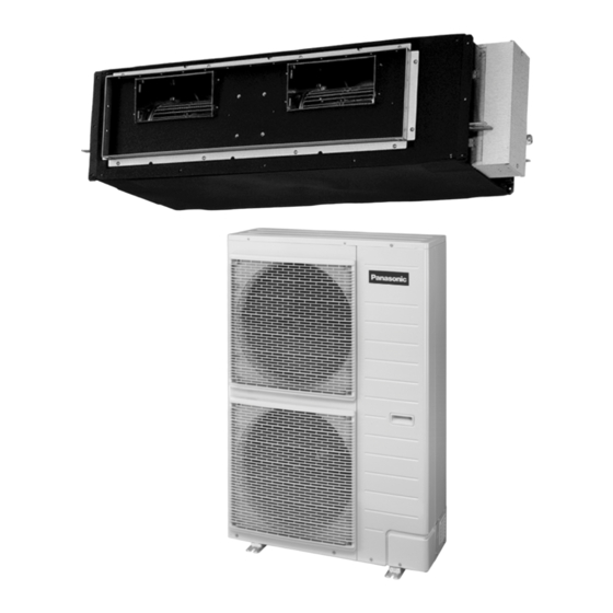
Panasonic CS-F24DD2E5 Service Manual
Panasonic air conditioner service manual
Hide thumbs
Also See for CS-F24DD2E5:
- Service manual (105 pages) ,
- Operating instructions manual (52 pages)
Table of Contents
Advertisement
CONTENTS
CS-F24DD2E5 CU-B24DBE5
CS-F28DD2E5 CU-B28DBE5
CS-F28DD2E5 CU-B28DBE8
CS-F34DD2E5 CU-B34DBE5
CS-F34DD2E5 CU-B34DBE8
CS-F43DD2E5 CU-B43DBE8
CS-F50DD2E5 CU-B50DBE8
Page
3
3
3
3
3
© 2005 Panasonic HA Air-Conditioning (M) Sdn Bhd
(11969-T). All rights reserved. Unauthorized copying
and distribution is a violation of law.
ORDER NO. MAC0509069C2
Air Conditioner
Page
4
4
4
5
Advertisement
Table of Contents

Related Manuals for Panasonic CS-F24DD2E5


Summary of Contents for Panasonic CS-F24DD2E5
-
Page 1: Table Of Contents
1.3. Caution during automatic address setting 2.3. A brand-new control method using the latest in technology 1.4. Operation range © 2005 Panasonic HA Air-Conditioning (M) Sdn Bhd (11969-T). All rights reserved. Unauthorized copying and distribution is a violation of law. - Page 2 10.3. Indoor unit installation B50DBE8 10.4. Outdoor unit installation 5 REFRIGERATION CYCLE 10.5. Wired remote controller installation 5.1. CS-F24DD2E5 CU-B24DBE5 CS-F28DD2E5 CU- 10.6. Twin systems installation B28DBE5 CU-B28DBE8 11 INSTALLATION & SERVICING AIR CONDITIONER 5.2. CS-F34DD2E5 CU-B34DBE5 CU-B34DBE8 CS- 11.1. Outline F43DD2E5 CU-B43DBE8 CS-F50DD2E5 CU-B50DBE8 11.2.
-
Page 3: Service Information
1 SERVICE INFORMATION Notice of Address setting for NEW Duct / NEW Outdoor Unit. The new Duct Type / New Outdoor models are possible to have address setting for twin control by automatic when main power supply is switched on. (Manual address setting is also possible by using Dip switch on Indoor unit P.C. -
Page 4: Features
2 FEATURES 2.1. Hide-away type 2.1.1. Thin, lightweight design • The unit has a low height, so it allows installation in limited ceiling spaces. The lightweight, attractive design simplifies installation, and matches virtually all room interiors. 2.1.2. Flexible installation • The powerful airflow enables a longer duct to be used. Since the air outlet can be installed away from the main unit, a variety of air conditioner layouts become possible. -
Page 5: Twin Operation
2.3. A brand-new control method using the latest in technology 2.3.1. Twin operation • Simultaneous air conditioning of wide spaces and corners is possible. Indoor units of same horsepowers and models can even be used in combination. • Master unit and slave-units can be set automatically in twin systems. -
Page 6: Specification
3 SPECIFICATION 3.1. CS-F24DD2E5 CU-B24DBE5 ITEM / MODEL Indoor Unit Outdoor Unit Main Body CS-F24DD2E5 CU-B24DBE5 Cooling Capacity BTU/h 22,500 Heating Capacity BTU/h 24,200 Refrigerant Charge-less Standard Air Volume for High Speed /min Hi 22 Hi 60 Hi 777 Hi 2120... -
Page 7: Cs-F28Dd2E5 Cu-B28Dbe5
13.7 13.9 Heat 12.5 12.6 13.0 Starting Current Power Factor Cool Heat 2.60 2.55 2.51 3.05 2.95 2.86 *Power Factor means total figure of compressor, indoor fan motor and outdoor fan motor. Panasonic Power source AC, 1~220V, 230V, 240V 50Hz... -
Page 8: Cs-F28Dd2E5 Cu-B28Dbe8
Cool 4.85 4.95 Heat 4.65 4.75 Starting Current Power Factor Cool Heat 2.60 2.55 2.51 3.05 2.95 2.86 *Power Factor means total figure of compressor, indoor fan motor and outdoor fan motor. Panasonic Power source AC, 3N~380V, 400V, 415V 50Hz... -
Page 9: Cs-F34Dd2E5 Cu-B34Dbe5
18.8 19.0 Heat 18.6 18.7 19.0 Starting Current Power Factor Cool Heat 2.57 2.52 2.45 2.87 2.81 2.77 *Power Factor means total figure of compressor, indoor fan motor and outdoor fan motor. Panasonic Power source AC, 1~220V, 230V, 240V 50Hz... -
Page 10: Cs-F34Dd2E5 Cu-B34Dbe8
3.68 3.75 Running Current Cool Heat Starting Current Power Factor Cool Heat 2.64 2.61 2.55 3.09 3.04 2.99 *Power Factor means total figure of compressor, indoor fan motor and outdoor fan motor. Panasonic Power source AC, 3N~380V, 400V, 415V 50Hz... -
Page 11: Cs-F43Dd2E5 Cu-B43Dbe8
4.66 4.78 Running Current Cool Heat Starting Current Power Factor Cool Heat 2.58 2.54 2.48 3.07 3.00 2.93 *Power Factor means total figure of compressor, indoor fan motor and outdoor fan motor. Panasonic Power source AC, 3N~380V, 400V, 415V 50Hz... -
Page 12: Cs-F50Dd2E5 Cu-B50Dbe8
5.13 5.18 Running Current Cool Heat Starting Current Power Factor Cool Heat 2.54 2.52 2.47 2.95 2.92 2.90 *Power Factor means total figure of compressor, indoor fan motor and outdoor fan motor. Panasonic Power source AC, 3N~380V, 400V, 415V 50Hz... -
Page 13: Dimensions
4 DIMENSIONS 4.1. CS-F24DD2E5 CS-F28DD2E5... -
Page 14: Cs-F34Dd2E5 Cs-F43Dd2E5 Cs-F50Dd2E5
4.2. CS-F34DD2E5 CS-F43DD2E5 CS-F50DD2E5... -
Page 15: Cu-B24Dbe5 Cu-B28Dbe5 Cu-B28Dbe8
4.3. CU-B24DBE5 CU-B28DBE5 CU-B28DBE8... -
Page 16: Cu-B34Dbe5 Cu-B34Dbe8 Cu-B43Dbe8 Cu-B50Dbe8
4.4. CU-B34DBE5 CU-B34DBE8 CU-B43DBE8 CU-B50DBE8... -
Page 17: Refrigeration Cycle
5 REFRIGERATION CYCLE 5.1. CS-F24DD2E5 CU-B24DBE5 CS-F28DD2E5 CU-B28DBE5 CU-B28DBE8... -
Page 18: Cs-F34Dd2E5 Cu-B34Dbe5 Cu-B34Dbe8 Cs-F43Dd2E5 Cu-B43Dbe8 Cs-F50Dd2E5 Cu-B50Dbe8
5.2. CS-F34DD2E5 CU-B34DBE5 CU-B34DBE8 CS-F43DD2E5 CU-B43DBE8 CS-F50DD2E5 CU-B50DBE8... -
Page 19: Block Diagram
6 BLOCK DIAGRAM 6.1. CS-F24DD2E5 CS-F28DD2E5 CS-F34DD2E5 CS-F43DD2E5 CS-F50DD2E5 6.2. CU-B24DBE5 CU-B28DBE5 6.3. CU-B34DBE5... -
Page 20: Cu-B28Dbe8
6.4. CU-B28DBE8 6.5. CU-B34DBE8 CU-B43DBE8 CU-B50DBE8... -
Page 21: Wiring Diagram
7 WIRING DIAGRAM 7.1. CS-F24DD2E5 CS-F28DD2E5 CS-F34DD2E5 CS-F43DD2E5 CS-F50DD2E5... -
Page 22: Cu-B24Dbe5 Cu-B28Dbe5
7.2. CU-B24DBE5 CU-B28DBE5... -
Page 23: Cu-B28Dbe8
7.3. CU-B28DBE8... -
Page 24: Cu-B34Dbe5
7.4. CU-B34DBE5... -
Page 25: Cu-B34Dbe8 Cu-B43Dbe8 Cu-B50Dbe8
7.5. CU-B34DBE8 CU-B43DBE8 CU-B50DBE8... -
Page 26: Wired Remote Control Operating Instructions
8 WIRED REMOTE CONTROL OPERATING INSTRUCTIONS 8.1. Name and function of each part OFF/ON button Used to start and stop the operation. FAN SPEED button Used to select the fan speed of high (HI), medium (MED), low (LO) or auto (AUTO). MODE button Used to select the operation of AUTO, HEAT, FAN, COOL, or DRY. -
Page 27: Remote Control - Display
8.2. Remote control - display... -
Page 28: Remote Control - Panel
8.3. Remote control - panel... -
Page 29: How To Set Remote Control Day And Time
8.4. How to set remote control day and time • The day and time need to be set when you turn on the power for the first time or after a long time has elapsed since the power was last turned on. •... -
Page 30: Daily Timer Setting
CLOCK Display (To set current Day and Time) Note: • The above display is shown if no valid timer setting is made. • If valid timer setting is made. − Timer and setting will be displayed. − If you want to check the current time and day, press “MODE button” once. (However, after a few seconds, the display will change back to Timer and the setting) 8.6. -
Page 31: Weekly Timer Setting
Final Display of Daily Timer: 8.7. Weekly timer setting • Display • How to Set Weekly Timer − You can set the Timer for 1 week (Monday to Sunday) with 6 programs per day. − ON-Timer can be set together with your desired temperature. However, this temperature will be used continuously. −... - Page 32 For example, if you want to set: A - Monday to Friday: Same time, 1st program ON 9:00 & 2nd program OFF 16:00. B - Only Wednesday: Additional 3rd program OFF 12:30 & 4th program ON 13:30. C - Only Saturday: 1st program ON 10:00 with 20°C & 2nd program OFF 14:00. D - Sunday: Holiday.
-
Page 33: Operation Detail
9 OPERATION DETAIL 9.1. Cooling operation • Cooling operation can be set using remote control. • This operation is applied to cool down the room temperature reaches the setting temperature set on the remote control. • Cooling Operation Time Diagram. -
Page 34: Heating Operation
9.2. Heating operation • Heating operation can be set using remote control. • This operation is applied to warm up the room temperature reaches the setting temperature set on the remote control. • Heating Operation Time Diagram. 9.3. Soft dry operation •... -
Page 35: Normal Control
9.6. Normal control 9.6.1. Cooling Indoor Fan Control • Manual Fan Speed Operation starts at High, Medium or Low speed set by remote control. • Auto Fan Speed When operation starts, or shifting to thermostat ON condition from thermostat OFF condition, indoor fan operates as below. Thermostat &... -
Page 36: Operation Control
9.6.3. Cooling Outdoor Fan Control • During cooling operation, outdoor fan speed changes according to outdoor pipe temperature. • The fan speed is controlled by the timing of turning the outdoor fan ON and OFF within an interval. • When outdoor pipe temperature increases, internal timing also increases. •... - Page 37 9.7.3. Powerful Control • To achieve setting temperature quickly. • Cooling powerful operation: − Setting temperature and thermostat shifting temperature are decrease by 2°C (lower limit 16°C). − Airflow direction is optimized regardless the air flow setting at remote control. −...
-
Page 38: Freeze Prevention Control
9.7.6. Dew Form Prevention Control • During cool or dry operation, if outdoor temperature is less than 30°C, and indoor fan speed is low or auto setting, indoor heat exchanger temperature become lower, dew form prevention control start to prevent dew form at indoor discharge grill. •... -
Page 39: Protection Control
9.7.9. Time Delay Safe Control • The compressor will not start for three minutes after stop of operation. 9.7.10. Outdoor Fan Remaining Heat Removal Control • When compressor stops, outdoor fan operates at High speed for 1 minute to remove the remaining heat. 9.7.11. - Page 40 9.8.2. Outdoor High-pressure Protection Control • The high-pressure protection control starts when high-pressure switch is activated less than 15 minutes after compressor startup. • During this protection control, compressor is shut down. And indoor unit is set to thermo-off status. •...
-
Page 41: Test Run
9.8.8. Four-way Valve Error Detection Control • The four-way valve error detection control starts when: − During cooling operation, when indoor heat exchanger temperature exceeds 45°C in 5 minutes after compressor starts. − During heating operation, when indoor heat exchanger temperature is below 5°C in 5 minutes after compressor starts. •... -
Page 42: Installation Instruction
Chargeless Refrigerant Liquid / Valve Gas / Valve Max (m) Max (m) Max (m) Max (m) (g/m) High CS-F24DD2E5 HIDE CS-F28DD2E5 AWAY (Me) CS-F34DD2E5 9.52 3-ways 15.88 3-ways TYPE CS-F43DD2E5 CS-F50DD2E5 Note : Piping elevation B = outdoor unit installed at top Piping elevation C = outdoor unit installed at bottom •... -
Page 44: Position Of The Centre Gravity
But when the piping length exceeds 30m, additional charge is required according to the following table. Example : CS-F24DD2E5 In case of 31m long pipe (one-way), the amount of refrigerant to be replenished is: (31 - 30) x 50 = 50g Model Name... -
Page 45: Indoor Unit Installation
10.3. Indoor unit installation DUCT TYPE AIR CONDITIONERS INSTALLATION INSTRUCTIONS Precautions in terms of safety Carry out installation work with reliability after thorough reading of this “Precautions in terms of safety”. • Precautions shown here are differentiated between Warnings Cautions . Those that have much chances for leading to significant result such as fatality or serious injury if wrong installation would have been carried out are listed compiling them especially into the column of Warnings . - Page 46 Warnings Wiring shall be connected securely using specified cables and fix them securely so that external force of the cables may not transfer to the terminal connection section. Imperfect connection and fixing leads to fire, etc. Cautions Carry out Earthing work. Drain piping should be made to ensure secure drainage Do not connect the Earth return to the gas pipe, according to the manual for installation work and carry out the...
- Page 47 9. If the power supply is subject to noise generation, add a suppressor. 10. Do not install the indoor unit in a laundry. Electric shocks may result. Note • Thoroughly study the following installation locations. 1. In such places as restaurants and kitchens, considerable amount of oil steam and flour adhere to the turbo fan, the fin of the heat exchanger and the drain pump, resulting in heat exchange reduction, spraying, dispersing of water drops, drain pump malfunction, etc.
-
Page 48: Installation Of Indoor Unit
10.3.3. Installation of indoor unit POSITION OF SUPENSION BOLT • Apply a joint-canvas between the unit and duct to absorb unnecessary vibration. • Install the unit learning to a drainage hole side as a figure for easy water drainage. -
Page 49: Refrigerant Piping
10.3.4. Refrigerant piping • Refrigerant is charged to the outdoor unit. For details, see the manual for installation work of outdoor unit. (Additional charging, etc.) 1. Brazing for piping. a. Execute brazing before tightening the flare nut. b. Brazing must be executed while blowing nitrogen gas. (This prevents generation of oxidized scale in copper pipe.) 2. -
Page 50: Heat Insulation
10.3.6. Heat Insulation Caution Be sure to perform heat insulation on the drain, liquid and gas piping. Imperfection in heat insulation work leads to water leakage. 1. Use the heat insulation material for the refrigerant piping which has an excellent heat-resistance (over 120°C). 2. -
Page 51: Electrical Wiring
10.3.7. Electrical wiring As to main power source and cable size of outdoor unit, read the installation manual attached to the outdoor unit. The units must be installed in accordance with applicable national and local regulations. Warning The units installed by a professional installer must be supplied from a dedicated electrical circuit. All electrical work must be carried out by a qualified technician according to proper technical standards for electrical work and according to installation manual for installation work. - Page 52 CONNECTING THE WIRES TO THE CONTROL BOX • Remove two screws , remove the control box cover, and then connect the wires by following the procedure given in the illustration. <INDOOR UNIT> • Remove the control box for electrical connection between the indoor and outdoor unit.
- Page 53 (Remote Controller address setting) (Refer to the Installation Manual which is provided with the remote controller for details.) • Two remote controllers (including the wireless remote controller) can be connected. However, remote control thermistor setting is not possible. • As for [master/slave] setting of remote controller, the automatic setting and manual setting are possible. Since manual setting is priority. •...
-
Page 54: Hand Over
10.3.11. Check the following items when installation is complete • After completing work, be sure to measure and record trial run properties, and store measuring data, etc. • Measuring items are room temperature, outside temperature, suction temperature, blow out temperature, wind velocity, wind volume, voltage, current, presence of abnormal vibration and noise, operating pressure, piping temperature, compressive pressure, airtight pressure. -
Page 55: Outdoor Unit Installation
10.4. Outdoor unit installation AIR CONDITIONERS OUTDOOR UNIT INSTALLATION INSTRUCTIONS Precautions in terms of safety Carry out installation work with reliability after thorough reading of this “Precautions in terms of safety”. • Precautions shown here are differentiated between Warnings Cautions . Those that have much chances for leading to significant result such as fatality or serious injury if wrong installation would have been carried out are listed compiling them especially into the column of Warnings . - Page 56 Warnings If installing inside a small room, measures should be taken to prevent refrigerant levels from building up to critical concentrations in the event of a refrigerant leak occurring. Please discuss with the place of purchase for advice on what measures may be necessary to prevent critical concentrations being exceeded.
- Page 57 b. Prevention measure for refrigerant piping Prevention measure for refrigerant piping is very important work to prevent water-dust-rubbish from getting in. All piping terminals need sealing such as shown below. Place Period of work Method of seal Outside More than 1 month Pinch Less than 1 month Pinch or taping...
- Page 58 For the use of a gas cylinder without siphon inside, turn it upside down and use it. (We recommend manifold with sight glass.) Caution Do not use a “CHARGE CYLINDER”. Caution As a rule, please collect all existing refrigerants in the system outside the system when the refrigerant leakage occurs by the system.
- Page 59 12. Be sure to leave enough space around the outdoor unit to maintain proper performance and to allow access for routine maintenance. • Allow enough space from any obstacles as shown in Fig. 1.2 below in order to prevent short-circuits from occurring. (If installing more than one outdoor unit, make the necessary space available as outlined in 13.) However, there should be at least 1 meter of free space above the unit.
- Page 60 • If a drain pipe needs to be installed, insert the accessory drain elbow into the mounting hole at the bottom of the outdoor unit, and connect a hose with an inside diameter of 15mm to this drain elbow. (The hose is not supplied.) If using the drain elbow, install the outdoor unit on a base which is at least 5cm high.
-
Page 61: Charging With Refrigerant
3. Notes when connecting the refrigerant pipes. • Use clean copper, pipes with no water or dust on the insides. • Use phosphorus-free, unjointed copper pipes for the refrigerant pipes. • If it is necessary to cut the refrigerant pipes, be sure to use a pipe cutter, and use compressed nitrogen or an air blower to clean out any foreign particles from inside the pipe. - Page 62 • Pump down operation − Operate the pump down according to the following procedures. Procedure Notes 1. Confirm the valve on the liquid side and the gas side is surely open. 2. Press the PUMP DOWN switch on outdoor printed board for 1 Perform the cooling operation for five minutes or more.
- Page 63 Earth lead wire shall be longer than other lead wires as shown in the figure for the electrical safety in case of the slipping out of the cord from the anchorage. • Power supply specifications Model name Leakage Circuit breaker Minimum Maximum Indoor/outdoor...
- Page 64 10.4.10. Connecting power supply cables CAUTION • For three phase model, never operate the unit by pressing the electromagnetic switch. • Never correct the phase by switching over any of the wires inside the unit. 10.4.11. Precautions with regard to test operation •...
- Page 65 NOTE 2 Do not short the remote control unit wires to each other. (The protection circuit will be activated and the units will not operate.) Once the cause of the short is eliminated, normal operation will then be possible. NOTE 3 When running the units in heating mode during test operation, be sure to run the units in cooling mode first before selecting this mode.
-
Page 66: Wired Remote Controller Installation
10.5. Wired remote controller installation Wired Remote Controller Installation Manual • Before installing the wired remote controller, be sure to thoroughly read the “Notes with regard to safety” section of the installation manual provided with the indoor unit. • After installing the wired remote controller, carry out a test operation to check that the remote controller functions properly, and also explain the operation and cleaning procedures to the customer in accordance with the details in instruction manual. -
Page 67: Remote Controller Installation
10.5.3. Remote controller installation • Be sure to turn off the main power before installing and connecting the remote controller. (If the remote controller is connected while the power is still turned on, the remote controller displays may not appear.) If no displays appear on the remote controller, check while referring to “If no remote controller displays appear”... - Page 68 NOTE − Be sure to use only the accessory screws. − Do not bend the lower case when tightening the screws. (If the screws are overtightened, damage may result.) − Do not remove the protective tape which is affixed to the upper case circuit board. •...
- Page 69 If remote control cable is embedded If installing with the remote control cable exposed 1. Embed an outlet box (JIS C 8336) into the wall, and then secure 1. Secure the remote controller base plate to the wall with two the remote controller base plate to the outlet box with the two accessory 4 mm screws.
- Page 70 [Manual Setting] Automatic address resetting for group control • The address settings for group control (air conditioner Nos. 1 to 16) can be reset automatically. 1. When operation is stopped, press for 5 seconds, continue the TEST RUN switch to display “00” (will be LOCAL MODE). 2.
-
Page 71: Test Operation
10.5.5. Test operation • Turn on the main power. • After 3 minutes have passed since the power was turned on, press the OFF/ON switch on the remote controller. (No operation occurs within 3 minutes after the power was turned on.) •... - Page 72 • You can then switch between the display for the previous problem and the problem before that by pressing the UP (TIMER) DOWN (TIMER) switches. • Press the CHECK switch once more to return to the normal display. Example of previous problem display Example of abnormality display before previous display •...
-
Page 73: Twin Systems Installation
10.6. Twin systems installation 10.6.3. Refrigerant charging 1. Calculate the piping length according to the following 10.6.1. General table1. 1. Two indoor units can be operated simultaneously with a • Calculation table 1. (piping length) single remote control unit. Note that individual operation is not possible. -
Page 74: Installation & Servicing Air Conditioner
11 INSTALLATION & SERVICING AIR CONDITIONER 11.1. Outline 11.1.1. About R410A refrigerant 1. Converting air conditioners to R410A Since it was declared in1974 that chlorofluorocarbons (CFC), hydro chlorofluorocarbons (HCFC) and other substances pose a destructive danger to the ozone layer in the earth’s upper stratosphere (20 to 40 km above the earth), measures have been taken around the world to prevent this destruction. -
Page 75: Tools For Installing/Servicing Refrigerant Piping
d. R410A refrigerating machine oil Conventionally, mineral oil or a synthetic oil such as alkylbenzene has been used for R22 refrigerating machine oil. Because of the poor compatibility between R410A and conventional oils like mineral oil, however, there is a tendency for the refrigerating machine oil to collect in the refrigerating cycle. -
Page 76: R410A Tools
11.2.2. R410A tools 1. Copper tube gauge for clearance adjustment (used when flaring with the conventional flaring tool (clutch type)) • This gauge makes it easy to set the clearance for the copper tube to 1.0-1.5 mm from the clamp bar of the flaring tool. - Page 77 5. Charging hose • The pressure resistance of the charging hose has been raised to match the higher pressure of R410A. The hose material has also been changed to suit HFC use, and the size of the fitting has been changed to match the manifold ports.
- Page 78 8. Electronic scale for refrigerant charging • Because of the high pressure and fast vaporizing speed of R410A, the refrigerant cannot be held in a liquid phase inside the charging cylinder when charging is done using the charging cylinder method, causing bubbles to form in the measurement scale glass and making it difficult to see the reading.
-
Page 79: Refrigerant Piping Work
11.3. Refrigerant piping work 11.3.1. Piping materials It is recommended that you use copper and copper alloy jointless pipes with a maximum oil adherence of 40 mg/10m. Do not use pipes that are crushed, deformed, or discolored (especially the inside surface). If these inferior pipes are used, impurities may clog the expansion valves or capillaries. - Page 80 Table 11 R410A flaring dimensions Nominal Outside Wall thickness A (mm) diameter diameter (mm) R410A flaring Conventional flaring tool (mm) tool, clutch type Clutch type Wing-nut type 6.35 0 - 0.5 1.0 - 1.5 1.5 - 2.0 9.52 0 - 0.5 1.0 - 1.5 1.5 - 2.0 12.70...
-
Page 81: Installation, Transferring, Servicing
b. Copper pipes Use only copper pipes with the thickness given in table 10, and with minimal impurities. Because the surface of the pipe is exposed, you should take special care, and also take measures such as marking the pipes to make sure they are easily distinguished from other piping materials, to prevent mistaken use. -
Page 82: Transferring (Using New Refrigerant Piping)
11.4.2. Transferring (Using new refrigerant piping) 1. Removing the unit a. Collecting the refrigerant into the outdoor unit by pumping down The refrigerant can be collected into the outdoor unit (pumping down) by pressing the TEST RUN button, even when the temperature of the room is low. - Page 83 3. Fully open the handle Lo of the manifold gauge, turn on the power of the vacuum pump and continue the vacuum process for at least one hour. 4. Confirm that the low pressure gauge shows a reading of -0.1 MPa (-76 cmHg), then fully close the handle Lo, and turn off the vacuum pump.
- Page 84 11.4.6. Brazing As brazing requires sophisticated techniques and experiences, it must be performed by a qualified person. In order to prevent the oxide film from occurring in the pipe interior during brazing, it is effective to proceed with brazing while letting dry nitrogen gas (N ) flow.
-
Page 85: Trouble Shooting Guide
12 TROUBLE SHOOTING GUIDE If test operation does not proceed correctly Carry out test operation after approximately 12 hours have passed since the power was turned on (crankcase heater is energized). If operation is started by using the remote control within 1 minute of turning on the power, the outdoor unit settings will not be made correctly and correct operation will not be possible. - Page 86 (When remote control display shows "power supply") Clock setting, and no timer setting (When remote control display shows "No power supply")
-
Page 87: During Twin Operation
12.2. During twin operation System example 1. The main power is turned on while the transmission wires between the indoor units are not connected. (open circuit at section A or B) Symptom Remote control unit : "check" flashes Error code : F30-01 (connected indoor capacity error) Indoor unit No.1 : LED1 on P.C.B flashes Indoor unit No.2 : no power supply Outdoor unit : LED6, 7 on P.C.B flashes (connected indoor capacity error) - Page 88 Error code : F30-01 (connected indoor capacity error) Indoor unit : LED1 on P.C.B flashes Outdoor unit : LED6, 7 on P.C.B flashes 4. The main power is turned on and the connection wire is all ok. If operation starts in this condition, combination of the outdoor unit and indoor unit will result in abnormal operation. Symptom Remote control unit : "check"...
-
Page 89: During Group Control Operation
12.3. During group control operation System example 1. The main power is turned on while the transmission wires between the indoor units are not connected. (open circuit at section A or B or C) Symptom Operation of indoor unit No.1 and No.3 is possible. However "check"... -
Page 90: Test Operation And Self Diagnosis
12.4. Test operation and self diagnosis 12.4.1. Test Run (Forced Cooling mode and Heating mode) 1. Always use a properly-insulated tool to operate the switch on the circuit board. (Do not use your finger or any metallic object.) 2. Never turn on the power supply unit until all installation work has been completed. 3. - Page 91 12.4.3. Test operation using the wired remote control 1. Check that "COOL" is displayed on the LCD, and then press the OFF/ON button to start test operation. 2. After pressing the OFF/ON button, press the TEST RUN button within 1 minute. 3.
- Page 92 The air conditioner No."01" appears during normal installation and use. When using group control, a different number may appear. The air conditioner No. can be displayed by pressing the air conditioner No. button. (=same as Temp. up and down button) When an abnormality occurs at this unit, "check"...
-
Page 93: Emergency Operation
12.5. Emergency operation If there is an abnormality in the temperature thermistor (disconnect or shorted), indoor unit cannot be operated. If abnormality detected in the indoor or outdoor unit, turn off the main power supply and find the cause. Check the resistance of each thermistor of both indoor and outdoor units by referring the resistance table as follows. Thermistor resistance table Resistance value (kΩ)±5% Temperature... -
Page 94: Self-Diagnosis Error Code Table
12.6. Self-diagnosis error code table • The display screen on the wired remote control unit and the self-diagnosis LEDs (green) on the outdoor unit printed circuit board in the outdoor unit can be used to indicate where the location of a problem is. Refer to the table below to remove the cause of the problem, and then re-start the air conditioner system. - Page 95 • The LED1 (green) illuminates to indicate that the microprocessor on LED8 Unit No. (when twin operation) the printed circuit board is operating normally. Master unit problem Slave unit problem If the LED is switched off is flashing irregularly. Check the power supply, and turn it off and then back on again.
-
Page 96: Technical Data
13 TECHNICAL DATA 13.1. Sound data... -
Page 102: Sound Measurement Point
13.2. Sound measurement point 13.2.1. Indoor unit 13.2.2. Outdoor unit... -
Page 103: Discharge And Suction Pressure
13.3. Discharge and suction pressure 13.3.1. Saturation temperature of discharge and suction pressure COOLING... - Page 104 HEATING...
-
Page 105: Capacity And Power Consumption
13.4. Capacity and power consumption 13.4.1. Cooling performance 13.4.1.1. CS-F24DD2E5 CU-B24DBE5 Model Cooling capacities are based on conditions CS-F24DD2E5 CU-B24DBE5 Single phase, 50Hz, 230V Cooling capacity Indoor temp. 27°C D.B. 19°C W.B. 6.6 kW Outdoor temp. 35°C D.B. Standard air volume 22 m... - Page 107 13.4.1.2. CS-F28DD2E5 CU-B28DBE5 Model Cooling capacities are based on conditions CS-F28DD2E5 CU-B28DBE5 Single phase, 50Hz, 230V Cooling capacity Indoor temp. 27°C D.B. 19°C W.B. 7.3 kW Outdoor temp. 35°C D.B. Standard air volume 22 m /min TC : Cooling Capacity SHC : Sensible Heat Capacity IPT : Cooling Power Consumption...
- Page 109 13.4.1.3. CS-F28DD2E5 CU-B28DBE8 Model Cooling capacities are based on conditions CS-F28DD2E5 CU-B28DBE8 3 phase, 50Hz, 400V Cooling capacity Indoor temp. 27°C D.B. 19°C W.B. 7.3 kW Outdoor temp. 35°C D.B. Standard air volume 22 m /min TC : Cooling Capacity SHC : Sensible Heat Capacity IPT : Cooling Power Consumption...
- Page 111 13.4.1.4. CS-F34DD2E5 CU-B34DBE5 Model Cooling capacities are based on conditions CS-F34DD2E5 CU-B34DBE5 Single phase, 50Hz, 230V Cooling capacity Indoor temp. 27°C D.B. 19°C W.B. 10 kW Outdoor temp. 35°C D.B. Standard air volume 36 m /min TC : Cooling Capacity SHC : Sensible Heat Capacity IPT : Cooling Power Consumption...
- Page 113 13.4.1.5. CS-F34DD2E5 CU-B34DBE8 Model Cooling capacities are based on conditions CS-F34DD2E5 CU-B34DBE8 3 phase, 50Hz, 400V Cooling capacity Indoor temp. 27°C D.B. 19°C W.B. 10 kW Outdoor temp. 35°C D.B. Standard air volume 36 m /min TC : Cooling Capacity SHC : Sensible Heat Capacity IPT : Cooling Power Consumption...
- Page 115 13.4.1.6. CS-F43DD2E5 CU-B43DBE8 Model Cooling capacities are based on conditions CS-F43DD2E5 CU-B43DBE8 3 phase, 50Hz, 400V Cooling capacity Indoor temp. 27°C D.B. 19°C W.B. 12.5 kW Outdoor temp. 35°C D.B. Standard air volume 40 m /min TC : Cooling Capacity SHC : Sensible Heat Capacity IPT : Cooling Power Consumption...
- Page 117 13.4.1.7. CS-F50DD2E5 CU-B50DBE8 Model Cooling capacities are based on conditions CS-F50DD2E5 CU-B50DBE8 3 phase, 50Hz, 400V Cooling capacity Indoor temp. 27°C D.B. 19°C W.B. 13.5 kW Outdoor temp. 35°C D.B. Standard air volume 45 m /min TC : Cooling Capacity SHC : Sensible Heat Capacity IPT : Cooling Power Consumption...
-
Page 119: Heating Performance
13.4.2. Heating performance 13.4.2.1. CS-F24DD2E5 CU-B24DBE5 Model Heating capacities are based on conditions CS-F24DD2E5 CU-B24DBE5 Single phase, 50Hz, 230V Heating capacity Indoor temp. 20°C D.B. 7.1 kW Outdoor temp. 7°C D.B. 6°C W.B. Standard air volume 22 m /min 13.4.2.2. CS-F28DD2E5 CU-B28DBE5... - Page 120 13.4.2.4. CS-F34DD2E5 CU-B34DBE5 Model Heating capacities are based on conditions CS-F34DD2E5 CU-B34DBE5 Single phase, 50Hz, 230V Heating capacity Indoor temp. 20°C D.B. 11.2 kW Outdoor temp. 7°C D.B. 6°C W.B. Standard air volume 36 m /min TC : Cooling Capacity SHC : Sensible Heat Capacity IPT : Cooling Power Consumption...
- Page 122 13.4.2.5. CS-F34DD2E5 CU-B34DBE8 Model Heating capacities are based on conditions CS-F34DD2E5 CU-B34DBE8 3 phase, 50Hz, 400V Heating capacity Indoor temp. 20°C D.B. 11.2 kW Outdoor temp. 7°C D.B. 6°C W.B. Standard air volume 36 m /min TC : Cooling Capacity SHC : Sensible Heat Capacity IPT : Cooling Power Consumption...
- Page 124 13.4.2.6. CS-F43DD2E5 CU-B43DBE8 Model Heating capacities are based on conditions CS-F43DD2E5 CU-B43DBE8 3 phase, 50Hz, 400V Heating capacity Indoor temp. 20°C D.B. 14 kW Outdoor temp. 7°C D.B. 6°C W.B. Standard air volume 40 m /min TC : Cooling Capacity SHC : Sensible Heat Capacity IPT : Cooling Power Consumption...
- Page 126 13.4.2.7. CS-F50DD2E5 CU-B50DBE8 Model Heating capacities are based on conditions CS-F50DD2E5 CU-B50DBE8 3 phase, 50Hz, 400V Heating capacity Indoor temp. 20°C D.B. 15 kW Outdoor temp. 7°C D.B. 6°C W.B. Standard air volume 45 m /min TC : Cooling Capacity SHC : Sensible Heat Capacity IPT : Cooling Power Consumption...
-
Page 128: Fan Performance
13.5. Fan performance 13.5.1. CS-F24DD2E5 Fan performance test report Fan performance curve... - Page 129 13.5.2. CS-F28DD2E5 Fan performance test report Fan performance curve...
- Page 130 13.5.3. CS-F34DD2E5 Fan performance test report Fan performance curve...
- Page 131 13.5.4. CS-F43DD2E5 Fan performance test report Fan performance curve...
- Page 132 13.5.5. CS-F50DD2E5 Fan performance test report Fan performance curve...
-
Page 133: Safety Device
13.6. Safety device 13.6.1. Indoor unit Indoor unit Heat pump model CS-F24DD2E5 CS-F28DD2E5 CS-F34DD2E5 CS-F43DD2E5 CS-F50DD2E5 Cooling only model For fan motor protection Internal °C protector °C For control protection Fuse 3.15 3.15 3.15 3.15 3.15 3.15 3.15 3.15 For fan motor protection Fuse 13.6.2. -
Page 134: Operating Characteristics
13.7. Operating characteristics S.C. : Starting Current R.C. : Running Current IPT : Power Consumption... -
Page 135: Replacement Parts
14 REPLACEMENT PARTS 14.1. Indoor unit CS-F24DD2E5, CS-F28DD2E5, CS-F34DD2E5, CS-F43DD2E5, CS-F50DD2E5... - Page 136 CS-F24DD2E5, CS-F28DD2E5, CS-F34DD2E5, CS-F43DD2E5, CS-F50DD2E5 REF. NO. PARTS NAME Q’TY QUANTITY PER 1 UNIT CS-F24DD2E5 CS-F28DD2E5 CS-F34DD2E5 CS-F43DD2E5 CS-F50DD2E5 ← ← ← Cabinet (Bottom) P02-T08080 P02-T08130 ← ← ← Cabinet (Bottom A) P02-T08090 P02-T08140 ← ← ← Drain pan P42-T03850 P42-T03920 ←...
-
Page 137: Outdoor Unit
14.2. Outdoor unit CU-B24DBE5, CU-B28DBE5, CU-B28DBE8... - Page 138 CU-B24DBE5, CU-B28DBE5, CU-B28DBE8...
- Page 139 PART DESCRIPTION QTY. CU-B24DBE5 CU-B28DBE5 CU-B28DBE8 ← ← BASE PAN ASSY CWD52K1102 COMPRESSOR 5JS315DAM21 5JS330DAF21 5JS330PBA21 ← ← ANTI-VIBRATION BUSHING CWH50055 ← ← NUT-COMPRESSOR MOUNT CWH561049 ← ← PACKING CWB811017 ← ← CRANKCASE HEATER CWA341017 ← CONDENSER COMPLETE CWB32C1706 CWB32C1716 ←...
- Page 140 CU-B34DBE5, CU-B34DBE8, CU-B43DBE8, CU-B50DBE8...
- Page 141 CU-B34DBE5, CU-B34DBE8, CU-B43DBE8, CU-B50DBE8...
- Page 142 CU-B34DBE5, CU-B34DBE8, CU-B43DBE8, CU-B50DBE8...
- Page 143 PART DESCRIPTION QTY. CU-B34DBE5 CU-B34DBE8 CU-B43DBE8 CU-B50DBE8 ← ← ← BASE PAN ASSY CWD52K1103 COMPRESSOR JT125G-P4V1 JT125G-P4Y1 JT160G-P4Y1 JT170G-P4Y1 ← ← ← ANTI-VIBRATION BUSHING CWH501081 ← ← ← NUT COMPRESSOR MOUNT CWH561049 ← ← ← CRANKCASE HEATER CWA341025 ← ← ←...
-
Page 144: Print Pattern
15 PRINT PATTERN 15.1. Indoor unit • INDOOR UNIT PRINTED CIRCUIT BOARD (MAIN) -
Page 145: Outdoor Unit
15.2. Outdoor unit • OUTDOOR UNIT PRINTED CIRCUIT BOARD (MAIN) [PHAAM] Printed in Malaysia SFYW0602 - 02...