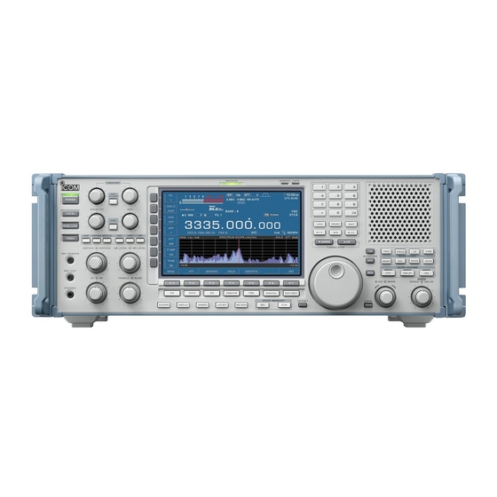
Icom IC-R9500 Service Manual
Communications receiver
Hide thumbs
Also See for IC-R9500:
- Price list (158 pages) ,
- Instruction manual (188 pages) ,
- Service manual addendum (392 pages)
Table of Contents
Advertisement
Quick Links
Advertisement
Table of Contents

Related Manuals for Icom IC-R9500


Summary of Contents for Icom IC-R9500
- Page 1 COMMUNICATIONS RECEIVER S-14323XZ-C1 Oct. 2007...
- Page 2 Addresses are provided on the inside back cover for your convenience. Icom Icom Inc. and logo are registered trademarks of Icom Incorporated (Japan) in the United States the United Kingdom Germany France Spain Russia and/or other countries.
-
Page 3: Table Of Contents
CONTENTS SECTION SPECIFICATIONS SECTION INSIDE VIEWS SECTION CIRCUIT DESCRIPITON RECEIVER CIRCUITS............3-1 FREQUENCY SYNTHESIZER CIRCUITS . - Page 4 CONTENTS (continued) SECTION WIRING DIAGRAM SECTION BLOCK DIAGRAM SECTION 10 SCHEMATIC DIAGRAM LOGIC UNIT AND MAMORY BOARD..........10-1 MAIN UNIT.
-
Page 5: Specifications
SECTION 1 SPECIFICATION General • Frequency coverage (unit: MHz) 0.005000–821.999999, 851.000000–866.999999, 896.000000–3335.000000 France 0.0050000–29.999999, 50.200000–51.200000, 87.500000–108.000000, 144.000000–146.000000, 430.000000–440.000000, 1240.000000–1300.000000 Europe, U.K., Canada, EXP, Australia, China 0.005000–3335.000000 • Operating mode : USB, LSB, CW, FSK, AM, FM, WFM, P25 • Number of memory channels : 1220 (1000 regular channels, 100 auto memory write channels, 100 skip channels, 20 scan edge channels) •... - Page 6 1 - 2...
-
Page 7: Section 2 Inside Views
SECTION 2 INSIDE VIEWS • TOP VIEW Rear side CONNECT-B UNIT CONNECT-A UNIT SCOPE/TV UNIT MAIN UNIT DC-DC UNIT OSC UNIT LOGIC UNIT 2 - 1... - Page 8 • BOTTOM VIEW RF-A UNIT PLL UNIT VCO-A BOARD VCO-B BOARD VCO-C BOARD RF-B UNIT MIX1 UNIT MIX2 UNIT ANT UNIT BPF UNIT Rear side 2 - 2...
-
Page 9: Circuit Descripiton
SECTION 3 CIRCUIT DESCRIPTION <The received signals from the MIX2 UNIT> 3-1 RECEIVER CIRCUITS The 2nd IF signal from the MIX2 UNIT is filtered by one BPF UNIT of 2nd IF filters (for BW=3 kHz, 6 kHz, 15 kHz, 50 kHz or The received signals from the “HF ANT1”... - Page 10 MIX1 UNIT MAIN UNIT (AUDIO DEMODULATION) The received signals from the RF-B UNIT are mixed with 1st The 3rd/4th IF signal from the RF-A UNIT is applied to the A/ LO signals from the PLL UNIT, to generate 1st IF signal. The D converter (IC1305) via buffer, and converted into the digital generated 1st IF signal is applied to the RF-B UNIT again, audio signal.
-
Page 11: Frequency Synthesizer Circuits
-VIDEO AM-DEMODULATION- (except for USA version) The 2nd IF signal divide at the splitter is amplifi ed and fi ltered, then converted into the 3rd IF (video IF) signal at 3rd mixer (IC2201). The converted video IF signal is amplifi ed, then passed through the video IF fi lters. The fi ltered video IF signal is applied to the video demodulation IC and AM-demodulated. - Page 12 1st LO signals for receiving 1GHz and below frequency are doubled by doublers on the BOUBLER BOARD. FIL2 BOARD IC-R9500 employed doubler which produces 1st LO signals Fil2 board doubles and fi lters 2nd LO signals. By expanding for the receiving 1.8 GHz and above, and improved the...
-
Page 13: Logic Circuits
LAN driver IC (IC404) conduct the LAN communications via LOGIC UNIT generally controls the whole of the circuit of the the pulse trans (T401). The EEPROM (IC403) stores the IC-R9500, and processes audio signal. settings for LAN connection. MAIN CONTROLLER COMPACT FLASH Two CPU’s;... -
Page 14: Port Allocations
3-5 PORT ALLOCATIONS MAIN CPU1 (LOGIC UNIT; IC103 ) Port Port Description Description number name number name Input port for the mode signal. 198, RESET, Input ports for the reset signal. TRST Input port for the clock signal. MRESET Input port for the manual reset signal. Input port for the data signal. - Page 15 MAIN CPU2 (LOGIC UNIT; IC604) Port Description number name Port Description number name DSPCK Outputs clock signal to the DSP IC. 5–9 H8_A0– DSPR Outputs data signal to the DSP IC. 11–17 H8_A5–A11, Output address bus signals. Outputs start signal to the internal 19, 20 H8–A12, A13, ISTA antenna tuner.
- Page 16 CPLD (LOGIC UNIT; IC605) Port Description number name H8_A13− Outputs data signal to CPU2 1−27 H8_WAIT# (IC604). DPL_BUSY Outputs data signal to dual SRAM 28−37 DPL_LB# (IC51). Outputs data signal to CPU2 TDO0 (IC604). Outputs serial data signal to CPU2 (IC604).
- Page 17 FRONT CPU (DISPLAY BOARD) Port Description number name Port Description number name Input port for [F-5] swicth. Outputs LCD contrast control Input port for [F-6] swicth. CNTV signal. Input port for [F-6] swicth. Outputs LCD brightness control Input port for [FM] swicth. BRIV signal.
-
Page 18: Adjustment Procedures
Push and hold [FM] and [WFM] keys then turn the power ON. e The main adjustment menu will appear as next page. ¤ CONNECTION IC-R9500 SG (for adjustment [HF] ) SG (for adjustments [V/U], [V/U1], [TV] and [WFM]) SG (for adjustment [V/U2]) •... - Page 19 ¤ MAIN ADJUSTMENT MENU DO NOT push Ext.S-METER (Not used) ADJUSTMENT ADJUSTMENTS ADJUSTMENTS (page 4-3) (page 4-3) (page 4-21) REFERENCE FERQUENCY ADJUSTMENTS ADJUSTMENT RX ADJUSTMENTS; (page 4-22) (page 4-3) • RX HF (page 4-4) • RX-V/U (page 4-6) • RX-V/U1 (page 4-7) •...
-
Page 20: Ext. S-Meter And Reference Frequency Adjustments
4-2 EXT. S-METER AND REFERENCE FREQUENCY ADJUSTMENTS [EXT Meter], [REF] NOTE: HOLD the adjustment condition (SG level and frequency etc.) until next ADJ item is displayed. ADJUSTMENT ITEM ADJUSTMENT CONDITION OPERATION VALUE EXTERNAL S-METER 1) Push [F-1•PRESET] key to select EXTERNAL S-METER ADJUSTMENT. [EXT Meter] 2) Rotate the [MAIN DIAL] to set the ADJ value. -
Page 21: Receive Adjustment (Hf)
4-4 RECEIVE ADJUSTMENTS (HF) [RX-HF] • Push [F-4•RX] key to enter the receive adjustment menu then push [F-1•RX-HF] key to select RX-HF ADJUSTMENT. • Connect an AC milivoltmeter to the [EXT-SP] jack. • Connect an SG to [HF-ANT1] and set as; Frequency : 14.1515 MHz Modulation... - Page 22 NOTE: HOLD the adjustment condition (SG level and frequency etc.) until next ADJ item is displayed. ADJUSTMENT ITEM ADJUSTMENT CONDITION OPERATION VALUE FIELD STREGTH METER • Set the SG as; Frequency : 14.1515 MHz Modulation : None [HF dBu −20dB] •...
-
Page 23: Receive Adjustment (V/U1)
NOTE: HOLD the adjustment condition (SG level and frequency etc.) until next ADJ item is displayed. ADJUSTMENT ITEM ADJUSTMENT CONDITION OPERATION VALUE ATTENUATION • Set the SG as; Push [F-7] key. (Automatic [HF ATT 6dB] Frequency : 14.1515 MHz adjustment) Level : +40 dBu [HF ATT 12dB]... -
Page 24: Receive Adjustment (V/U2)
4-6 RECEIVE ADJUSTMENTS (VHF and UHF) [RX-V/U1] • Push [F-3•RX V/U1] key to select RX V/U1 ADJUSTMENT. • Connect an AC milivoltmeter to the [EXT-SP] jack. • Connect an SG to [ANT1/HF ANT3] and set as; Modulation : None NOTE: HOLD the adjustment condition (SG level and frequency etc.) until next ADJ item is displayed. ADJUSTMENT ITEM ADJUSTMENT CONDITION OPERATION... - Page 25 NOTE: HOLD the adjustment condition (SG level and frequency etc.) until next ADJ item is displayed. ADJUSTMENT ITEM ADJUSTMENT CONDITION OPERATION VALUE S-METER(V/U1) • Set the SG as; Frequency : 50.1515 MHz [V/U1 S0 LEVEL] • Set the SG as; Push [F-7] key.
- Page 26 NOTE: HOLD the adjustment condition (SG level and frequency etc.) until next ADJ item is displayed. ADJUSTMENT ITEM ADJUSTMENT CONDITION OPERATION VALUE [V/U BPF2 (H) LOSS] • Set the SG as; Push [F-7] key. Frequency : 69.9815 MHz [V/U BPF3 (L) LOSS] •...
- Page 27 NOTE: HOLD the adjustment condition (SG level and frequency etc.) until next ADJ item is displayed. ADJUSTMENT ITEM ADJUSTMENT CONDITION OPERATION VALUE V/U PRE FREQUENCY • Set the SG as; CHARACTERISTIC Level : +40 dBu [V/U BPF1 (L) f] • Set the SG as; Push [F-7] key.
- Page 28 NOTE: HOLD the adjustment condition (SG level and frequency etc.) until next ADJ item is displayed. ADJUSTMENT ITEM ADJUSTMENT CONDITION OPERATION VALUE [V/U BPF9 (M2) f] • Set the SG as; Push [F-7] key. (Automatic Frequency : 910.0215 MHz adjustment) [V/U BPF9 (M3) f] •...
- Page 29 NOTE: HOLD the adjustment condition (SG level and frequency etc.) until next ADJ item is displayed. ADJUSTMENT ITEM ADJUSTMENT CONDITION OPERATION VALUE [V/U ATT10dB BPF8 (M3) f] • Set the SG as; Push [F-7] key. (Automatic Frequency : 687.5215 MHz adjustment) [V/U ATT10dB BPF8 (H) f] •...
- Page 30 NOTE: HOLD the adjustment condition (SG level and frequency etc.) until next ADJ item is displayed. ADJUSTMENT ITEM ADJUSTMENT CONDITION OPERATION VALUE [V/U ATT20dB BPF7 (H) f] • Set the SG as; Push [F-7] key. (Automatic Frequency : 499.9815 MHz adjustment) [V/U ATT20dB BPF8 (L) f] •...
-
Page 31: Receive Adjustment (Tv)
4-7 RECEIVE ADJUSTMENTS (VHF and UHF) [RX-V/U2] • Push [F-4•RX V/U2] key to select RX V/U2 ADJUSTMENT. • Connect the SG to [ANT2] and set as; Modulation : None NOTE: HOLD the adjustment condition (SG level and frequency etc.) until next ADJ item is displayed. ADJUSTMENT ITEM ADJUSTMENT CONDITION OPERATION... - Page 32 NOTE: HOLD the adjustment condition (SG level and frequency etc.) until next ADJ item is displayed. ADJUSTMENT ITEM ADJUSTMENT CONDITION OPERATION VALUE [Gain UP Total Gain V/U2-2 • Set the SG as; Measure the AF output level and set it as 0 dB PRE OFF] Frequency...
- Page 33 NOTE: HOLD the adjustment condition (SG level and frequency etc.) until next ADJ item is displayed. ADJUSTMENT ITEM ADJUSTMENT CONDITION OPERATION VALUE V/U2 BPF FREQUENCY • Set the SG and set as; CHARACTERISTIC Level : +40 dBu [V/U2-1 BPF f (1150.02MHz)] •...
- Page 34 NOTE: HOLD the adjustment condition (SG level and frequency etc.) until next ADJ item is displayed. ADJUSTMENT ITEM ADJUSTMENT CONDITION OPERATION VALUE [V/U2-3 BPF f (2650.02MHz)] • Set the SG as; Push [F-7] key. (Automatic Frequency : 2650.0215 MHz adjustment) [V/U2-3 BPF f (2700.02MHz)] •...
- Page 35 NOTE: HOLD the adjustment condition (SG level and frequency etc.) until next ADJ item is displayed. ADJUSTMENT ITEM ADJUSTMENT CONDITION OPERATION VALUE [V/U2-1 PRE f (1950.02MHz)] • Set the SG as; Push [F-7] key. Frequency : 1950.0215 MHz [V/U2-1 PRE f (1999.98MHz)] •...
- Page 36 NOTE: HOLD the adjustment condition (SG level and frequency etc.) until next ADJ item is displayed. ADJUSTMENT ITEM ADJUSTMENT CONDITION OPERATION VALUE V/U2 ATT FREQUENCY • Set the SG and set as; CHARACTERISTIC Level : +40 dBu [V/U2-1 ATT f (1150.02MHz)] •...
- Page 37 NOTE: HOLD the adjustment condition (SG level and frequency etc.) until next ADJ item is displayed. ADJUSTMENT ITEM ADJUSTMENT CONDITION OPERATION VALUE [V/U2-3 ATT f (2500.02MHz)] • Set the SG as; Push [F-7] key. Frequency : 2500.0215 MHz [V/U2-3 ATT f (2550.02MHz)] •...
- Page 38 4-8 TV ADJUSTMENT [TV] (except for USA version) • Push [F-5•TV] key to select TV ADJUSTMENT. • Connect the SG to [ANT1/HF ANT3] and set as; Frequency : 97.25 MHz Level : +54 dBu Modulation : None NOTE: HOLD the adjustment condition (SG level and frequency etc.) until next ADJ item is displayed. ADJUSTMENT ITEM OPERATION VALUE...
- Page 39 4-9 WFM ADJUSTMENT [WFM] • Push [F-6•WFM] key to select WFM ADJUSTMENT. • Connect the SG to [ANT1/HF ANT3] and set as; Modulation : None NOTE: HOLD the adjustment condition (SG level and frequency etc.) until next ADJ item is displayed. ADJUSTMENT ITEM ADJUSTMENT CONDITION OPERATION...
-
Page 40: Section 5 Parts List
SECTION 5 PARTS LIST [FRONT UNIT] [DISPLAY UNIT] ORDER ORDER DESCRIPTION DESCRIPTION LOCATION LOCATION 2510001390 SP 2844 SP BOX <FG> 7030003440 S.RES ERJ3GEYJ 102 V (1 k) 127.3/72 7030003440 S.RES ERJ3GEYJ 102 V (1 k) 123/71.4 7030003560 S.RES ERJ3GEYJ 103 V (10 k) 127.3/69.6 8900016130 CBL OPC-1684 (P1,N8,L70) -
Page 41: Display Unit
[DISPLAY UNIT] [LOGIC UNIT] ORDER ORDER DESCRIPTION DESCRIPTION LOCATION LOCATION R614 7030003860 S.RES ERJ3GE JPW V 9.3/71.1 1140011551 S.IC MT48LC16M16A2P-75 74/106.9 R615 7030003860 S.RES ERJ3GE JPW V 9.3/69.9 1140011551 S.IC MT48LC16M16A2P-75 74/114 R616 7030003860 S.RES ERJ3GE JPW V 9.3/67.5 IC51 1130011591 S.IC IDT70V24L15PFG 110.2/71... - Page 42 [LOGIC UNIT] [LOGIC UNIT] ORDER ORDER DESCRIPTION DESCRIPTION LOCATION LOCATION R103 7030003520 S.RES ERJ3GEYJ 472 V (4.7 k) 45.7/90.7 R243 7030003560 S.RES ERJ3GEYJ 103 V (10 k) 110.7/98.2 R104 7030003520 S.RES ERJ3GEYJ 472 V (4.7 k) 34.5/88.3 R244 7030003560 S.RES ERJ3GEYJ 103 V (10 k) 111.3/79.7 R105...
- Page 43 [LOGIC UNIT] [LOGIC UNIT] ORDER ORDER DESCRIPTION DESCRIPTION LOCATION LOCATION R378 7030003560 S.RES ERJ3GEYJ 103 V (10 k) 123.4/79.8 R603 7030003560 S.RES ERJ3GEYJ 103 V (10 k) 48.2/35.7 R381 7030003240 S.RES ERJ3GEYJ 220 V (22) 107.6/120.5 R604 7030003640 S.RES ERJ3GEYJ 473 V (47 k) 50.2/34.3 R382 7030003240 S.RES...
- Page 44 [LOGIC UNIT] [LOGIC UNIT] ORDER ORDER DESCRIPTION DESCRIPTION LOCATION LOCATION R901 7030003200 S.RES ERJ3GEYJ 100 V (10) 8.7/120 R1031 7030010900 S.RES ERJ3GEYJ 750 V (75) 167.2/120.8 R902 7030003860 S.RES ERJ3GE JPW V 44.2/38.3 R1032 7030003440 S.RES ERJ3GEYJ 102 V (1 k) 153.6/139.9 R903 7030003360 S.RES...
- Page 45 [LOGIC UNIT] [LOGIC UNIT] ORDER ORDER DESCRIPTION DESCRIPTION LOCATION LOCATION 4030011600 S.CER C1608 JB 1E 104K-T 63.6/122.5 C215 4030011600 S.CER C1608 JB 1E 104K-T 104.1/105.4 4030011600 S.CER C1608 JB 1E 104K-T 78.9/106.7 C216 4030011600 S.CER C1608 JB 1E 104K-T 100.3/86.6 4030011600 S.CER C1608 JB 1E 104K-T 74.2/106.7...
- Page 46 [LOGIC UNIT] [LOGIC UNIT] ORDER ORDER DESCRIPTION DESCRIPTION LOCATION LOCATION C407 4030011600 S.CER C1608 JB 1E 104K-T 44.4/50.6 C616 4030011600 S.CER C1608 JB 1E 104K-T 47.2/30.2 C408 4030011600 S.CER C1608 JB 1E 104K-T 53.2/57.3 C617 4030007130 S.CER C1608 CH 1H 101J-T 120.1/54.2 C409 4030011600 S.CER...
- Page 47 [LOGIC UNIT] [LOGIC UNIT] ORDER ORDER DESCRIPTION DESCRIPTION LOCATION LOCATION C919 4030006900 S.CER C1608 JB 1H 103K-T 10/126.2 C1065 4030017490 S.CER C1608 JB 1A 105K-T 17.2/10.8 C920 4030006900 S.CER C1608 JB 1H 103K-T 6.6/122.9 C1066 4030017490 S.CER C1608 JB 1A 105K-T 53.3/11 C921 4030006900 S.CER...
- Page 48 [LOGIC UNIT] [LOGIC UNIT] ORDER ORDER DESCRIPTION DESCRIPTION LOCATION LOCATION EP502 6910015970 S.BEA MMZ1608B 301CT-AS 146.3/126.5 EP1105 6910013310 S.BEA MMZ1608D121B 13.3/32.6 EP503 6910015970 S.BEA MMZ1608B 301CT-AS 138.5/30 EP1106 6910013310 S.BEA MMZ1608D121B 10.5/33.3 EP504 6910015970 S.BEA MMZ1608B 301CT-AS 153.5/37.9 EP1107 6910013310 S.BEA MMZ1608D121B 13.3/34 EP601...
- Page 49 [MAIN UNIT] [MAIN UNIT] ORDER ORDER DESCRIPTION DESCRIPTION LOCATION LOCATION IC101 1180000720 S.IC AN79L05M-(E1) 73.8/9.7 7030003320 S.RES ERJ3GEYJ 101 V (100) 95/91.2 IC201 1130013370 S.IC HD74LV2GT34AUSE-E 56.5/48 7030003860 S.RES ERJ3GE JPW V 93.7/91.2 IC202 1130006891 S.IC TC7S04FU (TE85R,F) 51.6/46 7030003320 S.RES ERJ3GEYJ 101 V (100) 108.8/96.3 IC203...
- Page 50 [MAIN UNIT] [MAIN UNIT] ORDER ORDER DESCRIPTION DESCRIPTION LOCATION LOCATION R1362 7030003800 S.RES ERJ3GEYJ 105 V (1 M) 73.3/46.2 R3132 7030003320 S.RES ERJ3GEYJ 101 V (100) 44.4/32 R1401 7030003320 S.RES ERJ3GEYJ 101 V (100) 76.8/48.8 R3141 7030003440 S.RES ERJ3GEYJ 102 V (1 k) 24.9/36.2 R1402 7030003860 S.RES...
- Page 51 [MAIN UNIT] [MAIN UNIT] ORDER ORDER DESCRIPTION DESCRIPTION LOCATION LOCATION C222 4030011600 S.CER C1608 JB 1E 104K-T 58.1/43.6 C1332 4030007090 S.CER C1608 CH 1H 470J-T 121.5/17.8 C301 4030007100 S.CER C1608 CH 1H 560J-T 67.6/23.4 C1333 4030017490 S.CER C1608 JB 1A 105K-T 128.6/17.2 C302 4030007160 S.CER...
- Page 52 [MAIN UNIT] [MAIN UNIT] ORDER ORDER DESCRIPTION DESCRIPTION LOCATION LOCATION C2421 4030011600 S.CER C1608 JB 1E 104K-T 113.7/82.9 C3259 4030007170 S.CER C1608 CH 1H 221J-T 25.2/86.7 C2422 4030011600 S.CER C1608 JB 1E 104K-T 113.7/79 C3260 4030007170 S.CER C1608 CH 1H 221J-T 26.5/86.7 C2423 4030011600 S.CER...
- Page 53 [BPF UNIT] [BPF UNIT] ORDER ORDER DESCRIPTION DESCRIPTION LOCATION LOCATION IC151 1130011530 S.IC CD74HC4094M96 7.9/42.3 R160 7030003240 S.RES ERJ3GEYJ 220 V (22) 14.1/60.3 IC152 1130011530 S.IC CD74HC4094M96 7.9/53 R161 7030003240 S.RES ERJ3GEYJ 220 V (22) 14.9/63.9 IC154 1160000131 S.IC TD62783AFG (S,EL) 18.9/6.8 R162 7030003240 S.RES...
- Page 54 [BPF UNIT] [BPF UNIT] ORDER ORDER DESCRIPTION DESCRIPTION LOCATION LOCATION 4030007040 S.CER C1608 CH 1H 180J-T 92.9/41.6 C273 4030007140 S.CER C1608 CH 1H 121J-T 34.8/61.9 4030007030 S.CER C1608 CH 1H 150J-T 92.3/45.5 C274 4030017810 S.CER C1608 CH 1H 102J-T 37.8/83.9 4030007050 S.CER C1608 CH 1H 220J-T 90.5/45.5...
- Page 55 [RF-A UNIT] [RF-A UNIT] ORDER ORDER DESCRIPTION DESCRIPTION LOCATION LOCATION IC130 1190002010 S.IC SD5400CY <TOMO> 67.8/92.9 L150 6180003570 COL SP0406-3R3K-6 IC210 1110006180 S.IC UPG2009TB-E3 66.5/65.4 L170 6200010740 S.COL C2520C-R27G-A 50.8/94.8 IC311 1180000421 S.IC TA78L05F (TE12R,F) 145/5.3 L190 6200011450 S.COL C2520C-R39G-A 30.9/94.4 IC380 1190002110 S.IC...
- Page 56 [RF-A UNIT] [RF-A UNIT] ORDER ORDER DESCRIPTION DESCRIPTION LOCATION LOCATION R111 7030003280 S.RES ERJ3GEYJ 470 V (47) 88.6/90.7 R808 7030003280 S.RES ERJ3GEYJ 470 V (47) 137.1/50.7 R130 7030000010 S.RES MCR10EZHJ JPW (000) 85.8/87.9 R809 7030003280 S.RES ERJ3GEYJ 470 V (47) 140.3/51.4 R131 7030003800 S.RES...
- Page 57 [RF-A UNIT] [RF-A UNIT] ORDER ORDER DESCRIPTION DESCRIPTION LOCATION LOCATION R1210 7030009851 S.RES ERA3YED 271V (270) 92.8/44.6 C212 4030006860 S.CER C1608 JB 1H 102K-T 67.3/66 R1211 7030009851 S.RES ERA3YED 271V (270) 95.5/13.6 C213 4030006860 S.CER C1608 JB 1H 102K-T 67.3/63.7 R1212 7030009841 S.RES ERA3YHD 330V (33)
- Page 58 [RF-A UNIT] [RF-A UNIT] ORDER ORDER DESCRIPTION DESCRIPTION LOCATION LOCATION C625 4030011600 S.CER C1608 JB 1E 104K-T 82.7/4.2 C1204 4030010760 S.CER C1608 CH 1H 331J-T 99.6/42.9 C626 4510008540 S.ELE EEE1CA100SR 93.2/5.4 C1205 4030010760 S.CER C1608 CH 1H 331J-T 101.2/13.6 C640 4030011600 S.CER C1608 JB 1E 104K-T 45.8/6.8...
- Page 59 [RF-B UNIT] [RF-B UNIT] ORDER ORDER DESCRIPTION DESCRIPTION LOCATION LOCATION IC801 1110006180 S.IC uPG2009TB-E3 43.1/114.5 L305 6200011410 S.COL C2520C-82NG-A 120.5/91.4 IC802 1110006180 S.IC UPG2009TB-E3 41.8/80.8 L306 6200010730 S.COL C2520C-68NG-A 121.3/87.7 IC1201 1110006970 S.IC MAALSS0038TR 29.7/99 L307 6200011800 S.COL C2520C-47NG-A 121/84.1 IC1202 1110007090 S.IC NJG1608KB2-TE1-#ZZZB...
- Page 60 [RF-B UNIT] [RF-B UNIT] ORDER ORDER DESCRIPTION DESCRIPTION LOCATION LOCATION R803 7030003320 S.RES ERJ3GEYJ 101 V (100) 60.8/102.7 C102 4030006880 S.CER C1608 JB 1H 472K-T 154.2/104.8 R812 7030003320 S.RES ERJ3GEYJ 101 V (100) 59.9/77.3 C103 4030007160 S.CER C1608 CH 1H 181J-T 148.3/106.4 R813 7030009810 S.RES...
- Page 61 [RF-B UNIT] [RF-B UNIT] ORDER ORDER DESCRIPTION DESCRIPTION LOCATION LOCATION C611 4030009510 S.CER C1608 CH 1H 010B-T 80.4/93.4 C1247 4030006900 S.CER C1608 JB 1H 103K-T 46.5/67 C612 4030007030 S.CER C1608 CH 1H 150J-T 82/91.3 C1251 4030007050 S.CER C1608 CH 1H 220J-T 45.2/64 C613 4030009530 S.CER...
- Page 62 [RF-B UNIT] [PLL UNIT] ORDER ORDER DESCRIPTION DESCRIPTION LOCATION LOCATION C1622 4510008540 S.ELE EEE1CA100SR 162.6/42.6 IC100 1130011530 S.IC CD74HC4094M96 43/27.3 C1623 4510008540 S.ELE EEE1CA100SR 150.7/26.8 IC101 1130009691 S.IC TC74HCT7007AF (F) 44.6/25 C1624 4030011600 S.CER C1608 JB 1E 104K-T 145.4/27.2 IC200 1160000131 S.IC TD62783AFG (S,EL) 28.9/26.1...
- Page 63 [PLL UNIT] [PLL UNIT] ORDER ORDER DESCRIPTION DESCRIPTION LOCATION LOCATION FI700 2020001820 S.CER SFECV10M5FA00-R0 101.9/41.7 R120 7030003360 S.RES ERJ3GEYJ 221 V (220) 24.7/16.8 FI5400 2020001810 S.CER SFECV10M7FA00-R0 148.4/48.8 R121 7030003360 S.RES ERJ3GEYJ 221 V (220) 24.3/7.8 R122 7030003550 S.RES ERJ3GEYJ 822 V (8.2 k) 45/33.7 R124 7030003550 S.RES...
- Page 64 [PLL UNIT] [PLL UNIT] ORDER ORDER DESCRIPTION DESCRIPTION LOCATION LOCATION R830 7030003500 S.RES ERJ3GEYJ 332 V (3.3 k) 102.6/83.9 R4004 7030003360 S.RES ERJ3GEYJ 221 V (220) 148.5/60.7 R831 7030003470 S.RES ERJ3GEYJ 182 V (1.8 k) 101.1/85.9 R4005 7030003360 S.RES ERJ3GEYJ 221 V (220) 148.5/62.5 R832 7030003470 S.RES...
- Page 65 [PLL UNIT] [PLL UNIT] ORDER ORDER DESCRIPTION DESCRIPTION LOCATION LOCATION R5329 7030007210 S.RES ERA3YEB 102V (1 k) 151.6/51.2 C708 4030011600 S.CER C1608 JB 1E 104K-T 101.7/47.5 R5400 7030003400 S.RES ERJ3GEYJ 471 V (470) 147.6/53.1 C750 4030006880 S.CER C1608 JB 1H 472K-T 76.3/46.8 R5401 7030003400 S.RES...
- Page 66 [PLL UNIT] [PLL UNIT] ORDER ORDER DESCRIPTION DESCRIPTION LOCATION LOCATION C1929 4050000290 S.FED CNF10R102S-TM 2.1/72.6 C4460 4030006860 S.CER C1608 JB 1H 102K-T 153.6/86.1 C2051 4030017810 S.CER C1608 CH 1H 102J-T 38.9/66.5 C4461 4030017810 S.CER C1608 CH 1H 102J-T 164.9/80.8 C2052 4030017810 S.CER C1608 CH 1H 102J-T 45.1/59...
- Page 67 [PLL UNIT] [SCOPE/TV UNIT] ORDER ORDER DESCRIPTION DESCRIPTION LOCATION LOCATION C5502 4030006880 S.CER C1608 JB 1H 472K-T 135.5/46.6 IC101 1110005040 S.IC M52342FP 600C 14.5/41.6 C5503 4030006880 S.CER C1608 JB 1H 472K-T 129.8/45.5 IC201 1130011741 S.IC TC7W66FK (TE85L,F) 28.4/69.6 C5504 4030007100 S.CER C1608 CH 1H 560J-T 134.7/41.5 IC202...
- Page 68 [SCOPE/TV UNIT] [SCOPE/TV UNIT] ORDER ORDER DESCRIPTION DESCRIPTION LOCATION LOCATION L1009 6200010860 S.COL C2520C-R10G-A (0.1U) 105.9/34.7 R410 7030003640 S.RES ERJ3GEYJ 473 V (47 k) 79.4/16.6 L1010 6200011410 S.COL C2520C-82NG-A 105.1/38.1 R411 7030003640 S.RES ERJ3GEYJ 473 V (47 k) 82/16.6 L1011 6200010720 S.COL C2520C-56NG-A 103.4/43...
- Page 69 [SCOPE/TV UNIT] [SCOPE/TV UNIT] ORDER ORDER DESCRIPTION DESCRIPTION LOCATION LOCATION R1605 7030003200 S.RES ERJ3GEYJ 100 V (10) 139.2/61.6 C208 4030006900 S.CER C1608 JB 1H 103K-T 29.7/57.7 R1606 7030003440 S.RES ERJ3GEYJ 102 V (1 k) 129.3/55 C295 4030007110 S.CER C1608 CH 1H 680J-T 74.9/85.7 R1608 7030003440 S.RES...
- Page 70 [SCOPE/TV UNIT] [SCOPE/TV UNIT] ORDER ORDER DESCRIPTION DESCRIPTION LOCATION LOCATION C670 4030007060 S.CER C1608 CH 1H 270J-T 35.8/3.7 C1316 4550006050 S.TAN TEESVA 0J 106M8R 78.6/46.2 C671 4030006980 S.CER C1608 CH 1H 070D-T 29.3/6.9 C1422 4030011600 S.CER C1608 JB 1E 104K-T 90.8/48 C672 4030009570 S.CER...
- Page 71 [SCOPE/TV UNIT] [OSC UNIT] ORDER ORDER DESCRIPTION DESCRIPTION LOCATION LOCATION J401 6510020081 S.CNR 52808-2071 (2090) 71/5.5 IC10 1180002610 S.REG BA12FP-E2 37.8/20 J1001 6510007020 CNR TMP-J01X-V6 IC91 1190002001 S.IC AD5260BRUZ50 26.8/12 J1301 6510007020 CNR TMP-J01X-V6 IC92 1130005721 S.IC TC7W04F (TE12L,F) 23.7/6.1 J1601 6510018961 S.CNR B2B-PH-SM4-TB (LF) (SN) 138.4/49.5...
- Page 72 [OSC UNIT] [DC-DC UNIT] ORDER ORDER DESCRIPTION DESCRIPTION LOCATION LOCATION 4510008680 S.ELE EEE1EA220SP 37.1/8.6 1190002450 S.IC BD9851FEV-E2 37.8/69.7 4030006880 S.CER C1608 JB 1H 472K-T 94.7/33.9 IC21 1190002450 S.IC BD9851FEV-E2 85.5/69.7 4030011600 S.CER C1608 JB 1E 104K-T 39.2/14.1 IC41 1190002450 S.IC BD9851FEV-E2 37.8/26.6 4030011600 S.CER...
- Page 73 [DC-DC UNIT] [DC-DC UNIT] ORDER ORDER DESCRIPTION DESCRIPTION LOCATION LOCATION 7030005691 S.RES ERA3YED 123V (12 k) 46.2/27.3 RL101 6330001060 RLY APQ 3311 (APQ3311K1) 7030005691 S.RES ERA3YED 123V (12 k) 47.8/26 RL102 6330001060 RLY APQ 3311 (APQ3311K1) 7030005321 S.RES ERA3YED 103V (10 k) 45.5/29.4 7030003440 S.RES ERJ3GEYJ 102 V (1 k)
- Page 74 [CONNECT-A UNIT] [CONNECT-B UNIT] ORDER ORDER DESCRIPTION DESCRIPTION LOCATION LOCATION 1120003040 S.IC ADM3202ARNZ 172.3/26.1 IC11 1110003091 IC LA4425A-E 1130005721 S.IC TC7W04F (TE12L,F) 155.8/28.2 IC21 1110006300 S.IC NJM2172V-TE1-#ZZZB 182.1/6.3 1130005252 S.IC TC74HC08AF (EL,F) 155.8/16.4 IC41 1110005610 S.IC NJM2058V-TE1-#ZZZB 145.4/9.1 IC81 1110002810 S.IC NJM2070M-TE1-#ZZZB 115.9/8.3 IC91...
- Page 75 [CONNECT-B UNIT] [CONNECT-B UNIT] ORDER ORDER DESCRIPTION DESCRIPTION LOCATION LOCATION R122 7030003600 S.RES ERJ3GEYJ 223 V (22 k) 68.1/18.8 6510023720 CNR LGY6501-0600C R123 7030003560 S.RES ERJ3GEYJ 103 V (10 k) 66.6/20 J101 6510024940 CNR HEC2305-016250 R124 7030003340 S.RES ERJ3GEYJ 151 V (150) 70.3/18.8 J111 6510023671 CNR...
- Page 76 [REG UNIT] [VCO2 BOARD] ORDER ORDER DESCRIPTION DESCRIPTION LOCATION LOCATION 5210000131 FUS FGB 4A PBF (FGB0 125V) Q4100 1530003550 S.TR 2SC5193-T1 15.7/5 [USA], [USA-1] Q4101 1530003550 S.TR 2SC5193-T1 18.7/6.2 5210001030 FUS 0234002.MXP Q4102 1590003520 S.TR BCR108T 3.8/3.6 [EUR], [UK], [FRA], [EXP], [AUS] Q4104 1590003570 S.TR BCR183T...
- Page 77 [VCO2 BOARD] [DOUBLER BOARD] ORDER ORDER DESCRIPTION DESCRIPTION LOCATION LOCATION C4117 4030017810 S.CER C1608 CH 1H 102J-T 1.8/3.5 Q2200 1530003781 S.TR 2SC5624VH-TL-E 29.8/16.7 C4118 4030017810 S.CER C1608 CH 1H 102J-T 6.5/1.6 Q2201 1530003781 S.TR 2SC5624VH-TL-E 32.3/16.6 C4119 4030017810 S.CER C1608 CH 1H 102J-T 13.2/3.9 C4120 4030007090 S.CER...
- Page 78 [DOUBLER BOARD] [FIL1 BOARD] ORDER ORDER DESCRIPTION DESCRIPTION LOCATION LOCATION C3052 4030017810 S.CER C1608 CH 1H 102J-T 25.3/16.6 D2751 1750000581 S.DIO 1SV307 (TPH3,F) 7.9/8.8 C3053 4030009540 S.CER C1608 CH 1H 1R5B-T 19.9/15.9 D2800 1750000581 S.DIO 1SV307 (TPH3,F) 21.9/7.9 C3054 4030009570 S.CER C1608 CH 1H 0R3B-T 18.7/18.2 D2850...
- Page 79 [FIL2 BOARD] [MIX1 UNIT] ORDER ORDER DESCRIPTION DESCRIPTION LOCATION LOCATION IC4450 1110006870 S.IC uPC2709TB-E3 7/16.1 1130012720 S.IC CD74HC4094PWR 12.1/8.1 IC101 1110006600 S.IC MGA-82563-TR1G 29.6/13.2 IC102 1110006970 S.IC MAALSS0038TR 41.7/13.2 D4500 1750000581 S.DIO 1SV307 (TPH3,F) 8.7/10 IC103 1110007060 S.IC uPC3223TB-E3 23.1/7.9 D4501 1750000581 S.DIO 1SV307 (TPH3,F)
- Page 80 [MIX1 UNIT] [MIX2 UNIT] ORDER ORDER DESCRIPTION DESCRIPTION LOCATION LOCATION C123 4030009550 S.CER C1608 CH 1H 2R5B-T 35.3/5.7 IC21 1190002051 S.IC SPM5001-TL-E 37.8/37.2 C124 4030009550 S.CER C1608 CH 1H 2R5B-T 30.3/4.4 IC101 1110006870 S.IC uPC2709TB-E3 8.4/20.7 C125 4030009550 S.CER C1608 CH 1H 2R5B-T 46/6 C126 4030009550 S.CER...
-
Page 81: Ant Unit
[MIX2 UNIT] [ANT UNIT] ORDER ORDER DESCRIPTION DESCRIPTION LOCATION LOCATION C144 4030009910 S.CER C1608 CH 1H 040B-T 16/40.7 IC101 1110006970 S.IC MAALSS0038TR 87.4/12.7 C161 4030009910 S.CER C1608 CH 1H 040B-T 11.5/33.4 IC201 1110006970 S.IC MAALSS0038TR 46.3/43.7 C162 4030006860 S.CER C1608 JB 1H 102K-T 20.8/28.6 IC202 1110006970 S.IC... - Page 82 [ANT UNIT] [ANT UNIT] ORDER ORDER DESCRIPTION DESCRIPTION LOCATION LOCATION R503 7030003200 S.RES ERJ3GEYJ 100 V (10) 132.9/23.9 C266 4030009540 S.CER C1608 CH 1H 1R5B-T 30.8/41 R601 7030003440 S.RES ERJ3GEYJ 102 V (1 k) 153.1/25.1 C267 4030009540 S.CER C1608 CH 1H 1R5B-T 30.8/44 R602 7030003290 S.RES...
- Page 83 [ANT UNIT] [VCO-B BOARD] ORDER ORDER DESCRIPTION DESCRIPTION LOCATION LOCATION EP1008 6910015970 S.BEA MMZ1608B 301CT-AS 22.3/11.7 Q1201 1560000491 S.FET 2SK508-T2B-A K52 5.3/9.7 EP1009 6910015970 S.BEA MMZ1608B 301CT-AS 22.3/10.5 Q1202 1530003550 S.TR 2SC5193-T1 8/18.4 EP1010 6910015970 S.BEA MMZ1608B 301CT-AS 22.3/9.3 Q1203 1530002060 S.TR 2SC4081 T106 R 6.6/15.8...
- Page 84 SECTION 6 MECHANICAL PARTS [CHASSIS PARTS] [CHASSIS PARTS] ORDER ORDER DESCRIPTION QTY. DESCRIPTION QTY. 8900015150 OPC-911A 6510000370 MR-DS 8900016160 OPC-1691 6510000330 NR-DS 8900016240 OPC-1700 8900016240 OPC-1700 6510003240 TMP-P01X-A1 8900015150 OPC-911A 6510003240 TMP-P01X-A1 8900016160 OPC-1691 6510003240 TMP-P01X-A1 8900016100 OPC-1678 6510003240 TMP-P01X-A1 8900016390 OPC-1713 6510003240 TMP-P01X-A1 6510003240 TMP-P01X-A1...
- Page 85 MP74 (CH)×10 [CHASSIS PARTS] • EXPLODED VIEW (OVERALL) ORDER DESCRIPTION QTY. MP110 8930072090 FERRITE SHEET (S) MP111 8930057730 Shield sponge (J) MP112 8930057730 Shield sponge (J) MP44 (CH) MP113 8930071550 Shield sponge (BM) MP114 8930069610 SPONGE (IV) MP2 (CH) MP115 8930045920 2056 SPONGE MP116 8950003640 Coating clip CS-2...
- Page 86 • EXPLODED VIEW (FRONT UNIT) LED BOARD SW-A BOARD MP88 (FR)×9 MP83 (FR) DIPLAY BOARD BT601(DS) MP10 (FR) VR-B BOARD MP94 (FR) JACK BOARD VR-A BOARD MP86 (FR) J5 (J) R4 (VA) MP94 (FR) MP60 (FR) R4 (VB) S1 (VA) J6 (J) EP1 (FR) MP17 (FR)
- Page 87 [FRONT UNIT] [FRONT UNIT] ORDER ORDER DESCRIPTION QTY. DESCRIPTION QTY. MP107 8930071770 2844 K-236 SHEET 2510001390 2844 SP BOX MP108 8930071780 2844 K-260 SHEET 8900016130 OPC-1684 MP109 8930071790 2844 K-261 SHEET MP110 8930063260 SPONGE (HV) 8900016130 OPC-1684 MP112 8930071840 HIMELON SHEET (CT) 8900016140 OPC-1690 8900016150 OPC-1679 MP113...
- Page 88 [VR-E BOARD] [SCOPE/TV UNIT] ORDER ORDER DESCRIPTION QTY. DESCRIPTION QTY. 6510020091 52808-0871 J301* 6510018961 B2B-PH-SM4-TB (LF) (SN) J401* 6510020081 52808-2071 2250000410 TP90D96E20-30F-2178-1 J1001 6510007020 TMP-J01X-V6 J1301 6510007020 TMP-J01X-V6 [VR-F BOARD] J1601* 6510018961 B2B-PH-SM4-TB (LF) (SN) J2001 6510007020 TMP-J01X-V6 ORDER J2301 6510007020 TMP-J01X-V6 DESCRIPTION QTY.
- Page 89 • EXPLODED VIEW (CHASSIS UNIT; TOP SIDE) MP162 (CH) @2 @1 MP5 (RG)×6 MP50 (CH)×6 MP99 (CH) MAIN UNIT MP50 (CH)×6 MP99 (CH) MP50 (CH)×6 DC-DC UNIT MP20 (CH) MP82 (CH)×5 MP1 (M) MP25 (CH) MP2 (M) MEMORY BOARD @6 !2 MP15 (CH) MP82 (CH) MP5 (RG)×16...
- Page 90 • EXPLODED VIEW (CHASSIS UNIT; BOTTOM SIDE) BPF UNIT MP410 (MIX1) MP405 (MIX1) MP203 (MIX2) MP210 (MIX2) MP108 (CH)×2 MP50 (CH)×4 MP802 (RFA) MP108 (CH)×2 MP1 (CH) MP50 (CH)×4 MP404 (MIX1) MP50 (CH)×4 MIX1 UNIT MIX2 UNIT W1 (MIX1) ANT UNIT MP34 (CH) PLL UNIT MP202 (MIX2)
- Page 91 [DC-DC UNIT] [BPF UNIT] ORDER ORDER DESCRIPTION QTY. DESCRIPTION QTY. RL101 6330001060 APQ3311 6330001721 ATN207-K1 RL102 6330001060 APQ3311 6330001721 ATN207-K1 RL21 6330001721 ATN207-K1 6510003461 B10B-EH-S (LF) (SN) RL22 6330001721 ATN207-K1 6510003441 B08B-EH-S (LF) (SN) RL41 6330001721 ATN207-K1 6510003441 B08B-EH-S (LF) (SN) RL42 6330001721 ATN207-K1 6510014961 B2B-ZR-SM4-TF (LF) (SN)
- Page 92 [RF-A UNIT] [MIX1 UNIT] ORDER ORDER DESCRIPTION QTY. DESCRIPTION QTY. 6510007020 TMP-J01X-V6 6510019971 52808-1071 6510007020 TMP-J01X-V6 J101* 6510023480 AYU1-1P-02676-120 J190 6510007020 TMP-J01X-V6 J301* 6510023480 AYU1-1P-02676-120 J210 6510007020 TMP-J01X-V6 J302 6510007020 TMP-J01X-V6 J290 6510007020 TMP-J01X-V6 J500 6510007020 TMP-J01X-V6 8900015660 OPC-1596 J671 6510007020 TMP-J01X-V6 8900015780 OPC-1634 J730...
- Page 93 [PLL UNIT] [ACCESSORIES] ORDER ORDER DESCRIPTION QTY. DESCRIPTION QTY. 6510021721 30FLT-SM2-TB (LF) (SN) 6450001281 TCP0587-715467 J450 6510007020 TMP-J01X-V6 6510023200 P031010 J500 6510007020 TMP-J01X-V6 5610000280 MP-12M J1301 6510007020 TMP-J01X-V6 J2400 6510007020 TMP-J01X-V6 5610000420 AP-338 J2501* 6510023480 AYU1-1P-02676-120 5610000430 AP331 J4500 6510007020 TMP-J01X-V6 J5150 6510007020 TMP-J01X-V6 5210000031 FGB 1A PBF...
- Page 94 SECTION 7 BOARD LAYOUTS J812 3R3V −12V • LOGIC UNIT (TOP VIEW) AFOUT AFOUTG PLAY PLAYG SPEECH SPEECHG DETO DETOG • MEMORY BOARD (TOP VIEW) PHNIK AFGV1 AFGV2 PHGV1 PHGV2 SQAFS SQACS SPON J820 RRMS +15V ANTS MOUT +15V SENI J811 −12V AGCOA...
- Page 95 • LOGIC UNIT (BOTTOM VIEW) • MEMORY BOARD (BOTTOM VIEW) 7 - 2...
- Page 96 • ANT UNIT (TOP VIEW) • BPF UNIT (TOP VIEW) • MIX-1 UNIT (TOP VIEW) R301 L301 IC301 IC202 C244 C252 L212 MP301 C243 C241 C249 C236 C250 C235 L210 L213 C239 C247 C233 C231 C230 L215 C264 R109 R108 R111 C106 C110...
- Page 97 • MIX-2 UNIT (BOTTOM VIEW) R121 MIX2 R141 B6563B TO RF-B J1305 1IF IN EP101 TO RF-B J1851 TO RF-A J210 TO PLL J4500 J201 J201 J101 IF OUT LO IN S-14323XH-P3 Printed in Japan © 2007 Icom Inc. 7 - 4...
- Page 98 • RF-B UNIT (TOP VIEW) • RF-A UNIT (TOP VIEW) J1851 2LOF2 2LOF3 2LOF1 J800 RASTB MDAT DRESL AGCIA CENTV +3R3V AGCOA −12V +15V +15V J1831 9 RBSTB MDAT +3R3V DRESL 7 - 5...
- Page 99 • RF-A UNIT (BOTTOM VIEW) • RF-B UNIT (BOTTOM VIEW) S-14323XH-P4 Printed in Japan © 2007 Icom Inc. 7 - 6...
- Page 100 • FIL-1 BOARD (TOP VIEW) • PLL UNIT (TOP VIEW) C2911 L2902 • VCO-A BOARD (TOP VIEW) C2910 C2901 C2908 L2900 D2852 L2852 R2152 D2850 B6582C C2857 C2851 C2858 C2856 L2850 C1313 C2811 L2802 C1001 D1307 C2810 C2801 C1312 VCO-A R1308 L2800 C1311...
- Page 101 • VCO2 BOARD (BOTTOM VIEW) • VCO-C BOARD (BOTTOM VIEW) R4306 L4300 R4308 R4309 R4310 L4200 R4208 R4210 Q1103 C1114 R1103 L4105 VCO2 R4106 L4100 B6743A R4109 R4105 C4121 S-14323XH-P5 Printed in Japan © 2007 Icom Inc. 7 - 8...
- Page 102 • SW-B BOARD (TOP VIEW) • SW-C BOARD (TOP VIEW) • SW-A BOARD (TOP VIEW) • VR-E BOARD • VR-C BOARD (TOP VIEW) (TOP VIEW) BASL TREL 3R3V B6273A VR-E • SENSOR BOARD MCHA 3R3V (TOP VIEW) BANKA MCHB BANKB BLACK •...
- Page 103 WFMK • DISPLAY BOARD (BOTTOM VIEW) • TENKEY BOARD (BOTTOM VIEW) +LDV 3R3V FINESK DLTFSK AUTOSK PROGSK MODESK PRIOSK SELSK MEMOSK SROFFD SRINFD SRLYD MCHA BANKA MCHB SSPDL BANKB SDLYL S-14323XH-P6 Printed in Japan © 2007 Icom Inc. 7 -10...
- Page 104 • CONNECT-A UNIT (TOP VIEW) [DISPLAY] (ANALOG RGB) [RS-232C] • JACK BOARD (TOP VIEW) [CI-V] [USB] [S/P DIF OUT] [LAN] [DATA IN] • OSC UNIT (TOP VIEW) t=1.6,(2) • CONNECT-B UNIT (TOP VIEW) [IF OUT] [REF I/O] [VIDEO IN] [VIDEO OUT] [LINE OUT] [SPEECH OUT] [SPARE]...
- Page 105 • JACK BOARD (BOTTOM VIEW) • CONNECT-A UNIT (BOTTOM VIEW) SPAFG SPAF RECRG RECRS RECOG RECOS PHAF PHNIK SPAF SPAFG • OSC UNIT (BOTTOM VIEW) • CONNECT-B UNIT (BOTTOM VIEW) S-14323XH-P7 Printed in Japan © 2007 Icom Inc. 7 - 12...
- Page 106 • DC-DC UNIT (TOP VIEW) • SCOPE/TV UNIT (TOP VIEW) • MAIN UNIT (TOP VIEW) J401 +15V +15V TVIF +3R3V −12V +3R3V +3R3V −12V +3R3V SSTB SOUD SDAT DETOUT SRST AFDET SIORST 19 7 - 13...
- Page 107 • DC-DC UNIT (BOTTOM VIEW) • SCOPE/TV UNIT (BOTTOM VIEW) • MAIN UNIT (BOTTOM VIEW) 7 - 14...
- Page 108 SECTION 8 WIRING DIAGRAMS • WIRING DIAGRAM (1) DATA REG UNIT u DISPLAY RS-232C CI-V HF ANT-Hi (ANALOG RGB) DIF OUT CF CARD HF ANT1 HFRF2 CONNECT-A UNIT CONNECT-B UNIT BPF UNIT DC-DC UNIT HFRF1 OPC-1635 OPC-519A OPC-1678 OPC-1680 OPC-1609 OPC-1683 OPC-1606 8900015770...
- Page 109 • WIRING DIAGRAM (2) VR-C VR-D 3R3V 3R3V BOARD BOARD +LDV +LDV TDTS TDTS TSUPK TSUPK LDAT LDAT TSDNK TSDNK RTCCK RTCCK +LDV +LDV NOTC1L NOTC1L FINESK FINESK NOTC2L NOTC2L AUTOSK DISAPLAY AUTOSK BOARD DLTFSK DLTFSK MODESK MODESK PROGSK PROGSK OPC-1684 OPC-1684 TENKEY...
- Page 110 SECTION 9 BLOCK DIAGRAMS • BLOCK DIAGRAM (1) 0.005-29.999999MHz IC1401 IC1401 IC1471 IC1002 FIL3K ANT-Hi IC500 IC1421 BA15532 SN74AHC1GU04 IC210 IC380 58.70MHz IC701 10.7MHz IC1002 RCA-Type SSB/CW/AM/FM=48kHz BA15532 P.AMP_SEL NJG1519KC1 NJG1519KC1 D1250 12dB 24dB P.AMP_SEL SD5400CY UPG2009 B W=3kHz D600 UPG2009 BW=50 K SN74AHC1GU04...
- Page 111 • BLOCK DIAGRAM (2) APCK NJM2058 APSO PLL UNIT IC3291 KIC7W53/BCR105 APSTB IC3321/Q3321 APBUSY AFDET_ AM P SELECT APOPT APAFSL1 APSI BUFF AFOUT 10.7MHz 450kHz APIRQ 2V1S IC3221 NJM2058 IC3221 IC3251 BW=280k BW=15k TA31136 IC3291 KIC7W53/BCR105 IC302 2V2S Q3221 TA31136 SN74LVC3G34 IC3322/Q3322 2V3S...
- Page 112 SECTION 10 SCHEMATIC DIAGRAMS • LOGIC UNIT (1) VDD3R3 R350 VDD3R3 VDD3R3 VDD1R5 PLL_ENABLEN# MMZ1608B301CT MMZ1608B301CT (L–2) EP205 EP206 X201 X202 MMZ1608B301CT MMZ1608B301CT CR-628 CR-780 C380 R381 L380 L381 AUD_CLK 0.33U 0.33U (L–3) VDD3R3 IC201 MT48LC16M16A2P IC202 MT48LC16M16A2P VDD3R3 SD _ D31 SD_DATA31 XTAL_USB SD _ D0...
- Page 113 • LOGIC UNIT (2) VDD3R3 VDD3R3 VDD3R3 VDD3R3 MMZ1608B301CT MMZ1608B301CT SYS_RES# VDD3R3 SH _ A22 CE01 SH _ A21 SH _ A20 FR_CS0# CE00 CE11 FR _ CS1# SH _ A19 SH _ A18 MMZ1608B301CT CE02 CE10 SH _ A17 SH _ A16 1 VDD 1 VDD...
- Page 114 • LOGIC UNIT (3) VDD3R3 VI _ DATA 7 VDD3R3A VDD3R3A VI _ DATA 6 VI _ DATA 5 MMZ1608B301CT VI _ DATA 4 MMZ1608B301CT VI _ DATA 3 VI _ DATA 2 MMZ1608B301CT VI _ DATA 1 (L–1) MMZ1608B301CT C550 R551 VI _ DATA 0...
- Page 115 • LOGIC UNIT (4) PSTPD R1401 J853 52808-1671 R1402 APBUSY R1403 APCK +3R3V L962 100U DRESH R960 R1404 APSO DSCL R970 DSDA R961 R1405 APSTB MDAT R971 R962 R1406 APOPT DSTB R972 TO MAIN J3252 DSON EP1263 R1407 APSI MMZ1608B301CT DSAP EP1273 MMZ1608B301CT...
- Page 116 • LOGIC UNIT (5) PCK/CON0 PDAT/CON1 MDAT CON2 +3R3V BSTB PSEL DRESL PSTB ODAT (L–5) HFANTI (L–5) VDD3R3 VDD3R3 DRESH HFANTO OSS1 (L–5) DSPCK OSS2 MMZ1608B301CT ASTB MDAT DSPR DSTB SDAT MDAT C602 DRESH R603 100P CRXD/CBSY SIOUD DSON MMZ1608B301CT 1SS355 (L–5) C601...
- Page 117 • MAIN UNIT (1) Q201 DRESH R203 APAFSL1 (M-4) BCR108T DAT4_ APAFSL2 (M-4) TO LOGIC J900 PSTDD_ L201 J3252 30FLT-SM2-TB APAFSL3 (M-4) CK4_ R3255 APAFSL1 APIRQ R3256 APAFSL2 APSI IC201 R3257 APAFSL3 APOPT (M-4) R3258 APIRQ R3259 APSI APSTB R3260 APOPT R3261 APSTB...
- Page 118 • MAIN UNIT (2) IF_I N A15V D3R3V R1333 C1332 R1317 C1303 R1313 R1334 I C1331 I C1301 KIC7W53FK NJM072BM C1317 I C1331 R1341 0.001 NJM072B M I C1304 C1321 R1309 VT/COMP IN - R1319 2.7K C1310 22 MSVA COMP NJM5534MD IC1332 KIC7W53FK...
- Page 119 • MAIN UNIT (3) DRESL IC2402 GND1 DVDD DVDD J2401 R2422 R2102 R3111N111A 4. 7 IC2404 IC2451 IC2452 D2001 I/O7 I/O6 1SR154 SN74LVC1G04DCK I/O5 SN74LVC1G04DCK I/O4 CVDD I/O3 R2452 52808-1071 I/O2 I/O1 IC2001 I/O0 SI-3012KS AT49BV040B EA20 EA19 EA18 EA17 EA16 EA15 EA14...
- Page 120 • MAIN UNIT (4) Q3141 R3141 BCR108T DRESH L3101 DAT4_ IC3324 HD74LV2GT34AUS PSTPD_ CK4_ C3104 DIVOUT BUM2I REFIN BUN2I PDIN BUN4I C3105 OSCO C3115 BUM2O BUN2O C3106 BUN4O OSCF OSCI C3114 IC3101 SYS-CLK SC-1246A R3131 SYSRESET STRB CON2 C3113 APAFSL1 IC3131 CON1 TEOUTH4...
- Page 121 • PLL UNIT (1) 1LO5V 1LO5V C1912 L1001 100U Q1001 CP1000 MP1001 CNF10R102S SC4081 L1000 R1006 4.7K R1011 MP1002 R1001 Q1000 IC1001 IC1000 R1000 1 RSET BCR183T 2 CP 2.7K DVDD 3 CPGND MUXOUT L1300 R1307 4 AGND 5 RFINB UPC4570G2 DATA 0.22U...
- Page 122 • PLL UNIT (2) R2307 IC2302 SN74AUC74RGYR R2309 Q2301 R2302 2CLR MP2001 1CLK IC2303 1PRE 2CLK 2PRE C2306 IC2301 S-812C25AUA 0.001 BCR08PN MP2002 SN74LVC1G04DCK 1LO5V Q2101 BCR08PN MP2400 J2400 L2053 TMP-J01X-V6 R2300 1SV307 R2304 D2052 C2303 L2400 L2401 C2405 C2407 C2409 HF1LO 1SV307...
- Page 123 • PLL UNIT (3) R4515 IC4501 R4403 R4516 L4400 C4566 R4520 L4503 0.001 C4563 0.001 0.15U UPC2709TB CP4001 C4567 R4512 0.001 D1451 L4450 D1453 R4051 MP4001 1SV307 1SV307 C4452 TO MIX2 J101 J4500 FIL2 TMP-J01X-V6 MP4002 D1452 L4451 D1454 C4513 BOARD 8.2N 1SV307...
- Page 124 • PLL UNIT (4) L5150 R5004 2LO8V C5906 R5009 CNF10R102S 2PLVL R5112 4.7K R5150 C5150 Q5150 J5150 2SC4403 TMP-J01X-V6 0.001 0.15U 0.18U R5155 C5151 L5151 L5152 TO RF-A J730 0.001 C5154 C5156 C5905 MP5002 R5011 CNF10R102S 3PLVL 1.8K MP5001 C P5001 C5904 L5000 L5200...
- Page 125 • PLL UNIT (5) 1F3S DOUBLER BOARD C2809 R3153 1F6S C2802 0.001 0.001 C3159 R2801 J2101 0.001 J2102 R2800 L2803 IMSA-9230B-1-03Z003-PT1 IMSA-9230B-1-06Z003-PT1 D3002 R3150 R3151 1LO8V 0.1U R2150 R2152 D2751 D2800 L2800 L2801 C2806 C2808 C2811 FIL1I FIL1O D3000 L3151 C3156 C3158 C3161...
- Page 126 • ANT UNIT J1001 52808-1671 VB10 MMZ1608B301CT EP1001 EP1101 MMZ1608B301CT MMZ1608B301CT EP1002 MMZ1608B301CT VB11 EP1102 C1201 MMZ1608B301CT EP1003 EP1103 MMZ1608B301CT Q1208 VUANT0 Q1206 Q1207 Q1209 Q1202 Q1203 Q1204 R1207 MPZ2012S331A BCR08P N 0. 1 BCR08PN BCR08P N BCR08PN BCR08PN EMD29 EMD29 EP1201 MPZ2012S331A...
- Page 127 • BPF UNIT HFB4 C153 IC154 TD62783AFG 0. 1 52808-1271 LR-458 LR-458 HFB0 R151 STROBE BCLK HFB1 R152 R301 DATA BDAT HFB2 R153 DATA R302 BSTB HFB3 R154 R303 BRST HFB4 R155 R304 ANTI HFB5 R156 R309 TO LOGIC J822 ANTO ATN207 HFB6...
- Page 128 • RF-A UNIT +15V +15V +10V +10V TMP-J01X-V6 MP131 C114 C117 TO PLL J500 J190 1SV307 220P C190 TMP-J01X-V6 Q170 C195 Q191 100U 0.033 2SC3950 2SC5501 HF1LO C170 R175 C191 0.01 C199 R200 TO PLL J2400 2SC5551F 0.01 L191 0.01 0.27U R110 R130...
- Page 129 • RF-B UNIT R502 R511 R102 R111 TBB5 TBB1 +15V MP1251 C1246 C1251 C1253 C1257 C1252 C1259 I C1251 0.001 0.001 0.001 0.001 L1256 L1260 R1251 1SV308 C1247 C1254 C1258 C1260 D1258 D501 C501 C505 C507 C509 L505 L506 L507 C516 D507 0.01...
- Page 130 • MIX1 UNIT • MIX2 UNIT J201 52808-1071 R104 EP101 MMZ1608B301CT X 8 MMZ1608B301CT EP201 EP205 2LOF1 52808-1071 EP202 EP206 2LOF2 EP203 EP207 2LOF3 TO RF-B J1851 MMZ1608B301CT EP204 EP208 +5VB RBSTB 1LOF4 CD74HC4094PW J101 MDAT TMP-J01X-V6 DRESL EP11 IC101 UPC2709TB C103 R106...
- Page 131 • FRONT UNIT (1) Q209 L210 Q204 L211 2SB1201 R339 2SB1201 +LDV +LDV DISPLAY BOARD Q210 R340 MA8033 2SC4081 D10F-#A814AY D 10F-#A814AY Q203 2SC4081 SML-A12MT T86J L602 3R3V (REMOTE) (LOCK) Q201 I C601 RX-4581 J301 T201 2SC3647 C202 CFLH D602 TO LCD BKL 0.01 52793-1070...
- Page 132 • FRONT UNIT (2) SW-B BOARD SW-A BOARD 30FLT-SM2-TB +LDV STBY LED 52808-2470 TDTS LDAT SML-512DW RTCCK STBD LS8J2M NOTC1L PWRD SML-512MW POWER ON LED NOTC2L PWRK [POWER] WFMK TREL [PBT CLEAR] SSBK [FM] [F-1] FSKK BASL LS8J2M LS8J2M TO DISPLAY J3 PWRK DIGIK DS12...
- Page 133 • CONNECT-A UNIT B2B-PH-SM4-TB J502 50FY-BMT-TB DATAVIDEO DATA IN DATAVIDEOE TO LOGIC J852 C D1# CFD3 CFD11 CFD4 CFD12 TCS4480-0141577 CFD5 CFD13 CFD6 TO CF CARD CFD14 CFD7 J501 CFD15 31-5620-050-719-871 0. 1 CE1# LGY6501-0600C MMZ1608Y102BT 1SS355 IC 2 TC7W04F CE2# 2SA1576 CD1#...
- Page 134 • CONNECT-B UNIT SPAFG SPAF LGY6501-0600C EXT-SP 0.0015 R4 4 IC41 ATX203 NJM2058V 1.5K 2SJ364 IC41 10 EEE-S 4.7K NJM2058V 2.2K C9 2 BCR108T 2SD1801 IC21 NJM2172V R5 2 D9 1 OP+INA OP+INB OP-INA OP-INB 10 EEE-S 8.2K 6.8K IC91 IC11 1SS355 NJM2125F...
- Page 135 • SCOPE/TV UNIT (1) C517 C521 L532 L514 L531 L512 4.5MSW 0.22U 0.47U CP71 CP73 D501 3.3U 3.3U D502 C518 C522 L204 100P 0.75P 0.75P 0.01 1SV307 C532 C536 1SV307 CP74 CP72 390P 100P 100P Q101 C511 C528 FI204 BCR08PN TPSKA6M50B00 0.
- Page 136 • SCOPE/TV UNIT (2) +15V +15V L1081 L1082 L1084 C299 C295 0.12U 0.1U R1105 EP1101 C1083 C1087 C1091 C1095 MMZ1608B301CT 2.5P R1209 C1084 C1088 C1092 C1096 R1212 Q1001 L1002 R1101 2SK1740 C2012C L1052 C1001 C1201 IC1101 L1204 C1054 C1101 L1101 C1103 L1103 C1107...
- Page 137 • DC-DC UNIT R155 +15V REG UNIT (RED) IC151 (BLACK) R153 (ORANGE) D151 MPZ2012S331A B10B-EH-S 3.3K 1SS355 LG_PWR EH-8 R131 VDD3R3VA B08B-EH-S NJM2904M R132 PWRS VDD3R3VB FI121 LG_PWR EP131 VDD3R3VA F141 ICP-S12 VDD3R3VB F142 ICP-S12 PWRS EP132 TO LOGIC J802 EP133 VDD15V VDD15V...
- Page 138 Phone : +34 (93) 590 26 70 Fax : +34 (93) 589 04 46 Glenwood Centre #150-6165 : http://www.icomspain.com Highway 17 Delta, B.C., V4K 5B8, Canada E-mail : icom@icomspain.com Phone : +1 (604) 952-4266 Fax : +1 (604) 952-0090 : http://www.icomcanada.com E-mail : info@icomcanada.com Unit 9, Sea St., Herne Bay, Kent, CT6 8LD, U.K.
- Page 139 S-14323XZ-C1-q 1-1-32 Kamiminami, Hirano-ku, Osaka 547-0003, Japan © 2007 Icom Inc.
Need help?
Do you have a question about the IC-R9500 and is the answer not in the manual?
Questions and answers