Chapters
Table of Contents

Related Manuals for Daikin AGZ 025D


Summary of Contents for Daikin AGZ 025D
- Page 1 Operating & Maintenance Manual OMM 1166-1 Group: Chiller Part No. OMM1166-1 Effective: March 2014 Air-Cooled Scroll Compressor Chiller AGZ025D – AGZ190D (Rev 0A) 25 to 190 Tons 50 - 60-Hertz, R-410A Software Version 251699201 © 2014 Daikin Applied...
-
Page 2: Table Of Contents
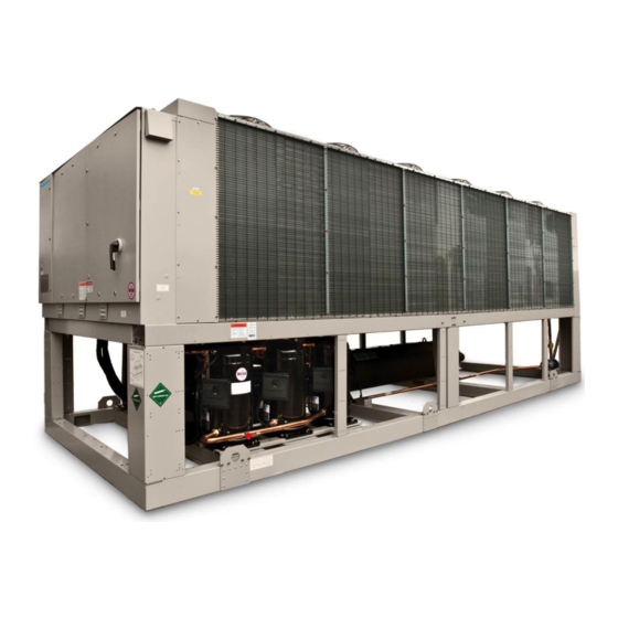
Cover picture: AGZ 190D Our facility is ISO Certified ©2014 Daikin Applied. Illustrations and data cover the Daikin Applied product at the time of publication and we reserve the right to make changes in design and construction at anytime without notice. -
Page 3: Introduction
, automatic compressor lead- Revision OA nameplate is AGZ………E11 lag to alternate the compressor starting sequence, and sequenced starting of Daikin Applied air-cooled global water chillers compressors. are complete, self-contained automatic refrigerating units. Every unit is completely The electrical control center includes all... - Page 4 Daikin Applied chillers are designed for this duty provided that the rate of change in AGZ 025D through 190D OMM 1166-1...
-
Page 5: Glycol Solutions
The type and handling of glycol used must be consistent with local codes Table 2, Ethylene Glycol Factors for Models AGZ 025D to 130D Freeze Point % E.G. - Page 6 Temperature drops outside this 6°F to 16°F and reduce the water flow. Maintain (3.3°C to 8.9°C) range can affect the control proper water treatment to provide system's capability to maintain acceptable optimum unit operation. control and are not recommended. AGZ 025D through 190D OMM 1166-1...
- Page 7 Table 6, Capacity and Power Derates, Models AGZ 025D to 130D Fouling Factor Chilled Water Delta Altitude 0.0001 (0.0176) 0.00025 (0.044) 0.00075 (0.132) 0.00175 (0.308) °F °C Cap. Power Cap. Power Cap. Power Cap. Power 0.978 0.993 0.975 0.991 0.963 0.987...
- Page 8 Drain and circuit. Operation of the heater cable is AGZ 025D through 190D OMM 1166-1...
-
Page 9: Operating/Standby Limits
Variable-Chilled Water Flow Systems For models AGZ 025D through AGZ 130D the part load flow rate in a variable chilled water flow system is 40% of nominal catalog full load flow (rated catalog tons x 2.4 = full load GPM). These minimum allowable flows are calculated to allow the chilled water flow to decrease progressively as the unit capacity decreases, but is restricted to 40% of rated full load flow. -
Page 10: Pressure Drop Curves
The curves are based on water use only. Use glycol adjustment factors located in the catalog Performance Section as required. Figure 1, Evaporator Pressure Drops. See following page for curve cross-reference See following page for curve cross-reference and min/max flow rates. AGZ 025D through 190D OMM 1166-1... - Page 11 613.2 38.3 38.7 114.5 180D 258.3 16.3 22.0 258.3 16.3 22.0 413.3 18.0 26.1 53.7 688.8 47.5 43.5 142.0 190D 270.1 17.0 26.9 270.1 17.0 26.9 432.2 22.0 27.3 65.7 720.3 58.1 45.4 173.7 OMM 1166-1 AGZ 025D through 190D...
- Page 12 Figure 2, Typical Field Control Wiring AGZ 025D through 190D OMM 1166-1...
-
Page 13: Microtech Iii Controller
Circuit Control Logic .....................29 Pumpdown Procedure ....................31 Compressor Control .......................31 Condenser Fan Control ....................32 EXV Control ........................34 Liquid Line Solenoid .....................35 Hot Gas Bypass Solenoid ....................35 Alarms ..........................35 Events…………………………………………………………………………..…….41 Clearing Alarms ......................43 Using the Controller…………………………………………………………………...44 OMM 1166-1 AGZ 025D through 190D... -
Page 14: Overview
DI2 Evaporator Flow Switch No Flow Flow Double Set Point/ Mode See sections on Unit Mode Selection and LWT Switch Target DI4 Remote Switch Remote Disable Remote Enable DI5 Unit Switch Unit Disable Unit Enable AGZ 025D through 190D OMM 1166-1... - Page 15 Fault No fault Circuit 2 PVM/GFP Fault No fault Note: The Motor Protection and MHP input signal are wired in series. If Motor Protection input is open, MHP Switch input will also be open. OMM 1166-1 AGZ 025D through 190D...
-
Page 16: Setpoints
Pressure inputs will be read using 0 to 5 volt ratiometric sensors. Nominal voltage range will be 0.5 to 4.5 volts. Pressure on the low side will be measured using Daikin Applied part number 331764501. Pressure on the high side will be measured using Daikin Applied part number 331764601. - Page 17 0°C (0°F) -5.0 to 5.0 °C (-9.0 to 9.0 °F) OAT sensor offset 0°C (0°F) -5.0 to 5.0 °C (-9.0 to 9.0 °F) Alarm Settings Low Evap Pressure Unload 689.5 KPA(100 PSI) See section 5.1.1 OMM 1166-1 AGZ 025D through 190D...
- Page 18 -100 to 100 KPA (-14.5 to 14.5 PSI) Cond pressure offset 0 KPA (0 PSI) -100 to 100 KPA (-14.5 to 14.5 PSI) Suction temp offset 0°C (0°F) -5.0 to 5.0 °C (-9.0 to 9.0 °F) AGZ 025D through 190D OMM 1166-1...
- Page 19 EXV Position set point on each circuit follows the actual EXV position while EXV Control = Auto. When EXV Control = Manual, the position set point should be changeable. The Clear Alarms and Network Clear Alarms settings are automatically set back to Off after being On for 1 second. OMM 1166-1 AGZ 025D through 190D...
-
Page 20: Security
The slope value calculated above will be a negative value as the water temperature is dropping. A pulldown rate is calculated by inverting the slope value and limiting to a minimum value of 0°C/min. LWT Error LWT error is calculated as: LWT – LWT target AGZ 025D through 190D OMM 1166-1... -
Page 21: Unit Enable
Stage Down Temperature = LWT target – (LWT target - 3.9°C) Unit Control Source Remote Unit Enable BAS Enable Unit Enable Switch Set Point Switch Input Set Point Set Point Local Network Network OMM 1166-1 AGZ 025D through 190D... -
Page 22: Unit Mode Selection
Off – Unit is not enabled to run Auto – Unit is enabled to run Pumpdown – Unit is doing a normal shutdown Transitions between these states are shown in the following diagram. POWER PUMPDOWN AUTO Diagram explanation on following page. AGZ 025D through 190D OMM 1166-1... -
Page 23: Power Up Start Delay
Unit State = Off and Low OAT Lockout is active Off:All Cir Disabled Unit State = Off and both circuits unavailable Off:Unit Alarm Unit State = Off and Unit Alarm active Continued next page. OMM 1166-1 AGZ 025D through 190D... -
Page 24: Evaporator Pump Control
LWT is less than the Evap Freeze set point – 0.6°C (1.1°F) and LWT sensor fault isn’t active T2 – Start to Run Requires the following Flow ok for time longer than evaporator recirculate time set point AGZ 025D through 190D OMM 1166-1... -
Page 25: Lwt Target
Cool Set Point 1 Local COOL Cool Set Point 2 Network COOL BAS Cool Set Point Local COOL w/Glycol Cool Set Point 1 Local COOL w/Glycol Cool Set Point 2 Network COOL w/Glycol BAS Cool Set Point OMM 1166-1 AGZ 025D through 190D... -
Page 26: Unit Capacity Control
A minimum amount of time, defined by the Stage Down Delay set point, should pass between decreases in the capacity stage. This delay should not apply when the LWT drops below the Shut Down Temperature (unit should immediately shut down). AGZ 025D through 190D OMM 1166-1... -
Page 27: Unit Capacity Overrides
The maximum unit capacity can be limited by a 4 to 20 mA signal on the Demand Limit analog input. This function is only enabled if the Demand Limit set point is set to ON. The maximum unit capacity stage is determined as shown in the following tables: OMM 1166-1 AGZ 025D through 190D... - Page 28 OAT is greater than 46.6°C (115.9°F), circuit 2 is limited to running all but one compressor. This limit will allow the unit to operate at higher temperatures than 46.6°C (115.9°F). AGZ 025D through 190D OMM 1166-1...
-
Page 29: Circuit Functions
The circuit will always be in one of four states: Off – Circuit is not running Preopen – Circuit is preparing to start Run – Circuit is running Pumpdown – Circuit is doing a normal shutdown OMM 1166-1 AGZ 025D through 190D... - Page 30 Any of the following are required: Unit State = Off Unit State = Pumpdown Circuit switch is open Circuit mode is disable Circuit Rapid Stop alarm is active Circuit Pumpdown alarm is active AGZ 025D through 190D OMM 1166-1...
-
Page 31: Pumpdown Procedure
Applies only to circuit 2. Compressor Control Compressors should run only when the circuit is in a run or pumpdown state. They should not be running when the circuit is in any other state. OMM 1166-1 AGZ 025D through 190D... -
Page 32: Condenser Fan Control
Fan Outputs On Fan Stage Fan Outputs On 1,2,3 1,2,3 1,2,3,4 1,2,4 1,2,3,4 5 Fans 1,2,3,4,5 Fan Stage Fan Outputs On 7 Fans Fan Stage Fan Outputs On 1,2,3 1,2,4 1,2,3,4 1,2,3 1,2,4 1,2,3,4 1,2,4,5 1,2,3,4,5 AGZ 025D through 190D OMM 1166-1... - Page 33 This is accomplished by adding the new fan stage up deadband to the VFD target. The higher target causes the VFD logic to decrease fan speed. Then, every 2 seconds, 0.1°C (0.18°F) is subtracted from the VFD target until it is equal to the saturated condenser temperature target set point. OMM 1166-1 AGZ 025D through 190D...
-
Page 34: Exv Control
7.2°C (13°F) and the should reflect that it is manual control. expansion valve has been within 5% of its current maximum position. The maximum should increase at a rate of 0.1% every six AGZ 025D through 190D OMM 1166-1... -
Page 35: Liquid Line Solenoid Valve
This alarm can be cleared at any time manually via the keypad or via the BAS clear alarm command. If active via trigger condition 1: When the alarm occurs due to this trigger, it can auto reset the first two times each day with the third occurrence being manual reset. OMM 1166-1 AGZ 025D through 190D... - Page 36 Reset: This alarm can be cleared manually via the keypad or BAS command when communication between main controller and the extension module is working for 5 seconds. Compressor Module 2 Comm Failure Trigger: Communication with the I/O extension module has failed. Action Taken: Rapid stop of circuit 2. AGZ 025D through 190D OMM 1166-1...
-
Page 37: Unit Problem Alarms
Trigger: Unit is configured with primary and backup pumps, pump #2 is running, and the pump control logic switches to pump #1. Action Taken: Backup pump is used. Reset: This alarm can be cleared manually via the keypad or BAS command OMM 1166-1 AGZ 025D through 190D... -
Page 38: Unit Warning Alarms
This alarm should trigger when Freeze time is exceeded, Low Ambient Start is not active, and Circuit State = Run. It should also trigger if Evaporator Press < 137.9 KPA (20 PSI) and Circuit State = Run. AGZ 025D through 190D OMM 1166-1... - Page 39 Reset: This alarm can be cleared manually via the controller keypad if the input is closed. Low OAT Restart Fault Trigger: Circuit has failed three low OAT start attempts. Action Taken: Rapid stop circuit. Reset: This alarm can be cleared manually via the keypad or via BAS command. OMM 1166-1 AGZ 025D through 190D...
-
Page 40: Circuit Events
Reset: While still running, the event will be reset if evaporator pressure > Low Evaporator Pressure Hold SP + 90 KPA(13 PSI). The event is also reset if the circuit is no longer in the run state. AGZ 025D through 190D OMM 1166-1... -
Page 41: Circuit Warning Alarms
These events are stored in a log separate from alarms. This log shows the time and date of the latest occurrence, the count of occurrences for the current day, and the count of occurrences for each of the previous 7 days. OMM 1166-1 AGZ 025D through 190D... -
Page 42: Unit Events
This event is triggered if all of the following are true: circuit state = Run more than one compressor is running on the circuit condenser pressure > High Condenser Pressure – Unload set point AGZ 025D through 190D OMM 1166-1... -
Page 43: Clearing Alarms
Alarm Log. If not corrected, the On will and date stamp for the event occurrence plus immediately change back to OFF and the unit the count of the event occurrences on the will remain in the alarm condition OMM 1166-1 AGZ 025D through 190D... -
Page 44: Using The Controller
(parameters) “below” the currently displayed items or an “up/down” arrow to indicate there are lines “above and below” the currently displayed line. The selected line is highlighted. Each line on a screen can contain status-only information or include changeable data fields (setpoints). AGZ 025D through 190D OMM 1166-1... -
Page 45: Navigating
Once a valid password has been entered, the controller allows further changes and access without requiring the user to enter a password until either the password timer expires or a different password is entered. OMM 1166-1 AGZ 025D through 190D... - Page 46 Temperatures menu, which contains temperatures values and setpoints. The first line is Evap LWT, rotate wheel until Cool LWT 1 is highlighted. Press the wheel to enter edit mode. Rotate wheel until new setpoint is reached, then press wheel to accept the new value and exit edit mode. AGZ 025D through 190D OMM 1166-1...
-
Page 47: Menus
Quick Menu View/Set Unit View/Set Circuit Unit Status Active Setpoint Evap Leaving Water Temp Unit Capacity Unit Mode Time Until Restart Alarms Scheduled Maintenance Review Operation Manual Control U-10 Commission Unit U-11 About Chiller U-12 OMM 1166-1 AGZ 025D through 190D... - Page 48 Circuit #2 Cx-1 Screen U-6 From Screen U-1 Time Until Restart No password Operator Links to screen Compressor 1 Cycle Time Remaining Compressor 2 Cycle Time Remaining Compressor 3 Cycle Time Remaining Continued next page. AGZ 025D through 190D OMM 1166-1...
- Page 49 Configuration U-23 Set-Up U-14 Date/Time/Schedules U-16 Power Conservation U-17 Alarm Limits U-26 Calibrate Unit Sensors U-27 Calibrate Circuit Sensors U-35 LON Setup U-18 BACnet IP Setup U-19 BACnet MSTP Setup U-20 Continued next page. OMM 1166-1 AGZ 025D through 190D...
- Page 50 Ice Cycle Time Remaining Clear Ice Cycle Delay Evap Pump Control Evap Recirculate Timer Evap Nominal Delta T Evap Pump 1 Run Hours Evap Pump 2 Run Hours Remote Service Enable Continued next page. AGZ 025D through 190D OMM 1166-1...
- Page 51 DLS End Month DLS End Week Screen U-17 From Screen U-4, U-11 Power Conservation No password Operator Links to screen Unit Capacity Demand Limit Enable Demand Limit Value LWT Reset Enable Continued next page. OMM 1166-1 AGZ 025D through 190D...
- Page 52 NC Dev 1 NC Dev 2 BACnet BSP Screen U-21 From Screen U-4, U-11 Modbus Setup No password Operator Links to screen Apply Changes Address Parity Two Stop Bits Baud Rate Load Resistor Continued next page. AGZ 025D through 190D OMM 1166-1...
- Page 53 From Screen U-4 Design Conditions No password Operator Links to screen Evap Entering Water Temp @ Design Evap Leaving Water Temp @ Design Evap Design Water Flow Evap Design Approach Cond Design Ambient Continued next page. OMM 1166-1 AGZ 025D through 190D...
- Page 54 Change 3 Time/Date 3 Change 4 Time/Date 4 Change 5 Time/Date 5 Change 6 Time/Date 6 Screen U-29 From Screen U-4 Menu Password No password Operator Links to screen Password Disable Continued next page. AGZ 025D through 190D OMM 1166-1...
- Page 55 PVM Input State Evaporator Flow Switch State Remote Switch Input State External Alarm Input State Double Set Point Input State Evaporator LWT Input Resistance Evaporator EWT Input Resistance OAT Input Resistance Continued next page. OMM 1166-1 AGZ 025D through 190D...
- Page 56 Comp 3/4 Cmpx-1 Comp 5/6 Cmpx-1 Condenser Cx-6 Cx-7 Calibrate Sensors Cx-8 Screen Cx-2 From Screen U-9 Circuit x Status/Settings No password Operator Links to screen Circuit Status Circuit Mode Circuit Capacity Continued next page. AGZ 025D through 190D OMM 1166-1...
- Page 57 Operator Links to screen Test Comp 1/2 Output Test Comp 3/4 Output Test Comp 5/6 Output Test Liquid Line Output Test Hot Gas Output Test EXV Position Test Fan Output 1 Continued next page. OMM 1166-1 AGZ 025D through 190D...
- Page 58 Condenser Design Approach EXV Position Evap Leaving Water Temp Evap Entering Water Temp Screen Cx-5 From Screen Cx-1 Status/Settings Cirx No password Operator Links to screen Circuit Status Circuit Mode Circuit Capacity Continued next page. AGZ 025D through 190D OMM 1166-1...
- Page 59 Cond Pressure Offset Suction Temp Suction Temp Offset Screen Cmpx-1 From Screen Cx-1 Circuit x Comp x No password Operator Links to screen Compressor State Last Compressor Start Last Compressor Stop Run Hours Number Of Starts OMM 1166-1 AGZ 025D through 190D...
-
Page 60: Optional Low Ambient Fan Vfd
Do not to switch off power to the inverter while the motor is running (unless it is an emergency stop) to avoid equipment damage. Also, do not install or use disconnect switches in the wiring from the inverter to the motor (except thermal disconnect). AGZ 025D through 190D OMM 1166-1... -
Page 61: Vfd Interface (Hmi)
Lit while the drive is operating the motor. LO/RE Light Lit while the operator is selected to run the drive (LOCAL mode). ALM LED Light Refer to ALARM (ALM) LED Displays on page 63 OMM 1166-1 AGZ 025D through 190D... -
Page 62: Lcd Display
Pressing [F2] switches between forward and reverse DATA Pressing [F2] scrolls to the next display Function Key 2 (F2) Pressing [F2] scrolls the cursor to the right RESET Pressing [F2] resets the existing drive fault error AGZ 025D through 190D OMM 1166-1... - Page 63 Safe Disable function. The STOP key was pressed while drive was running in REMOTE. The drive was powered up with b1-17 = 0 (default) while the Run command was active. Examples OMM 1166-1 AGZ 025D through 190D...
- Page 64 “Fault Reset” as default Input S4 (H1-04 = 14) Turn off the main power supply if the above methods do not reset the fault. Reapply power after the HMI display has turned off. AGZ 025D through 190D OMM 1166-1...
-
Page 65: Recommended Periodic Inspection
IM 968-1, L Communication Module ORKS IM 969-2, Modbus® Communication Module ED 15120, Protocol Information for MicroTech III chiller, BACnet and L ORKS ED 15121, Protocol Information for MicroTech III chiller, Modbus OMM 1166-1 AGZ 025D through 190D... -
Page 66: Startup
Be prepared to record all operating parameters required by the “Compressorized Equipment Warranty Form”. Return this information within 10 working days to Daikin Applied as instructed on the form to obtain full warranty benefits. - Page 67 These should be checked again after 3 months of operation and at least yearly thereafter. 2. Check all control wiring by pulling on the wire at the spade connections and tighten all screw connections. Check plug-in relays for proper seating and to insure retaining clips are installed. OMM 1166-1 AGZ 025D through 190D...
-
Page 68: Operation
-10F (-23.3C). The control looks at the saturated discharge temperature and varies the fan speed to hold the temperature (pressure) at the “target” temperature. This temperature is established as an input to a setpoint screen labeled “Sat Condenser Temp Target”. AGZ 025D through 190D OMM 1166-1... - Page 69 Code 2 Alert will open the M2-M1 contacts. The Alert will reset after 30 minutes and the M2-M1 contacts will close if the resistance of the motor PTC circuit is back in the normal range. The module OMM 1166-1 AGZ 025D through 190D...
-
Page 70: System Adjustment
The color of the moisture indicator is an indication of the dryness of the system and is extremely important when the system has been serviced. Immediately after the system has been opened for service, the element may indicate a wet condition. It is recommended that the equipment operate for AGZ 025D through 190D OMM 1166-1... -
Page 71: Refrigerant Charging
Power must be supplied to the heaters 8 hours before starting the compressors. Evaporator Models AGZ 025D through 130D The evaporator is a compact, high efficiency, dual circuit, brazed, plate-to-plate type heat exchanger consisting of parallel stainless steel plates. - Page 72 Phase Voltage Monitor (Optional) Factory settings are as follows: Trip Delay Time, 2 seconds Voltage Setting, set at nameplate voltage. Restart Delay Time, 60 seconds AGZ 025D through 190D OMM 1166-1...
-
Page 73: Unit Maintenance
125F (52C). repairing any fin damage. Daikin Applied The option can be factory or field installed as a recommends the use of foaming coil cleaners kit. -
Page 74: Planned Maintenance Schedule
Coil cleaning can be required more frequently in areas with a high level of airborne particles. Be sure fan motors are electrically locked out. * Never Megger motors while they are in a vacuum to avoid damage to the motor. AGZ 025D through 190D OMM 1166-1... -
Page 75: Service
410A is rose/light maroon. Must be DOT POE type oil is used for compressor approved, R-410A with 400 psig rating. Open lubrication. This type of oil is extremely cylinders slowly. hydroscopic which means it will quickly OMM 1166-1 AGZ 025D through 190D... -
Page 76: Refrigerant Charging
Check the sight glass to be sure there is no R-22. The software functionality is the same refrigerant flashing. for either refrigerant. With outdoor temperatures above 60F (15.6C), all condenser fans should be operating and the liquid line temperature AGZ 025D through 190D OMM 1166-1... - Page 77 PERCENT CIRCUIT PRESSUREDROP ACROSS LOADING (%) with normal subcooling. The maximum FILTER DRIER PSIG (KPA) recommended pressure drops across the filter- 100% 10 (69) 8 (55.2) drier are shown below. 5 (34.5) 4 (27.6) OMM 1166-1 AGZ 025D through 190D...
-
Page 78: Evaporator
The evaporators on AGZ-C models 030 - 130 are cleaning and testing, no service work should be brazed plate type, and on models 140, 160, and required on the evaporator. 180 they are shell-and-tube type. Other than AGZ 025D through 190D OMM 1166-1... -
Page 79: Agz-D Troubleshooting Chart
Reset thermostat setting for application. Thermostat control band not set properly Set control band wider. Compressor Faulty water temperature sensor Replace. Staging Intervals Insufficient water flow Adjust flow. Too Short Rapid load swings Stabilize load. OMM 1166-1 AGZ 025D through 190D... - Page 80 Discharge valve partially shut Open valve. Thermal Blown compressor internal gasket Replace gasket. Protection Switch Voltage range or imbalance Check and correct. Open High superheat Adjust to correct superheat. Compressor bearing failure Replace compressor . AGZ 025D through 190D OMM 1166-1...
- Page 84 Daikin Applied Training and Development Now that you have made an investment in modern, efficient Daikin Applied equipment, its care should be a high priority. For training information on all Daikin Applied HVAC products, please visit us at www.DaikinApplied.com and click on Training, or call 540-248-9646 to speak with the Training Department.
Need help?
Do you have a question about the AGZ 025D and is the answer not in the manual?
Questions and answers