Table of Contents
Advertisement
Advertisement
Table of Contents

Related Manuals for HP Compaq Presario F500


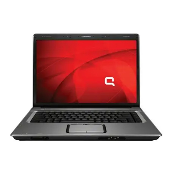
Summary of Contents for HP Compaq Presario F500
- Page 1 Compaq Presario F500 Notebook PC Maintenance and Service Guide...
- Page 2 Company under license. The information contained herein is subject to change without notice. The only warranties for HP products and services are set forth in the express warranty statements accompanying such products and services. Nothing herein should be construed as constituting an additional warranty.
-
Page 3: Table Of Contents
Table of contents 1 Product description 2 External component identification Top components ........................4 Pointing devices ......................4 Keys ........................5 Front components ........................6 Right-side components ......................7 Left-side components ......................... 8 Bottom components ........................9 3 Unknown user password 4 Illustrated parts catalog Serial number location ...................... - Page 4 Computer feet ......................31 Memory module ...................... 31 RTC battery ......................33 WLAN module ......................34 Optical drive ......................35 Switch cover ......................37 Keyboard ....................... 39 Power button board ....................41 Display assembly ....................43 Top cover ....................... 48 Audio board ......................
- Page 5 Phillips PM2.5×4.0 screw ....................... 86 Hex HM5.0×7.0 Standoff ....................... 88 Phillips PM2.0×6.0 screw ....................... 89 Phillips PM2.5×5.0 captive screw .................... 90 9 Backup and Recovery Recovering system information ....................91 Backing up your information ..................91 When to back up ..................91 Back up suggestions .................
-
Page 7: Product Description
Product description Category Description Product Name Compaq Presario F500 Notebook PC Processors AMD Turion™ 64 Mobile Technology processors ● TL-52 (1.6-GHz, 1-MB L2 cache) ● TL-50 (1.6-GHz, 512-KB L2 cache) ● MK-36 (2.0-GHz, 1-MB L2 cache) Mobile AMD Sempron™ processors ●... - Page 8 Category Description ● DVD-RW and CD-RW Combo Drive ● DVD±RW and CD-RW Super Multi Double-Layer Combo Drive Diskette drive Supports external USB drive only ● Audio Supports Microsoft Gold requirements ● Presario-branded Altec Lansing speakers ● Modem 56K V.92 data/fax modem ●...
- Page 9 Category Description Operating Preinstalled: system ● Windows Vista™ Premium ● Windows Vista Home Basic ● Free DOS Serviceability End-user replaceable parts: ● AC adapter ● Battery (system) ● Hard drive ● Memory module ● WLAN module ● Optical drive...
-
Page 10: External Component Identification
External component identification Top components Pointing devices Item Component Function ● TouchPad light Blue: TouchPad is enabled. ● Amber: TouchPad is disabled. TouchPad Moves the pointer and selects or activates items on the screen. TouchPad horizontal scroll zone Allows you to scroll left or right. Left and right TouchPad buttons Function like the left and right buttons on an external mouse. -
Page 11: Keys
Keys Item Component Function Speakers Produce sound. num lock key Enables numeric lock, turns on the embedded numeric keypad, and turns on the num lock light. Embedded numeric keypad keys Can be used like the keys on an external numeric keypad. Arrow keys Move the cursor around the screen. -
Page 12: Front Components
Front components Item Component Function ● Power light On: The computer is on. ● Blinking: The computer is in the Sleep state. ● Off: The computer is off or in Hibernation. ● Battery light On: A battery is charging. ● Blinking: A battery that is the only available power source has reached a low battery level. -
Page 13: Right-Side Components
Right-side components Item Component Function Optical drive Reads an optical disc. USB port (select models only) Connects an optional USB device. Power connector Connects an AC adapter. Security cable slot Attaches an optional security cable to the computer. NOTE: The security cable is designed to act as a deterrent, but it may not prevent the computer from being mishandled or stolen. -
Page 14: Left-Side Components
Left-side components Item Component Function S-Video-out jack Connects an optional S-Video device, such as a television, VCR, camcorder, overhead projector, or video capture card. External monitor port Connects an external VGA monitor or projector. RJ-45 (network) jack Connects a network cable. RJ-11 (modem) jack Connects a modem cable. -
Page 15: Bottom Components
Bottom components Item Component Function Battery bay Holds the battery. Battery release latch Releases the battery from the battery bay. Optical drive Reads an optical disc. Memory module compartment Contains the memory module slots, the WLAN module slot, and the RTC battery. NOTE: To prevent an unresponsive system and the display of a warning message, replace with... -
Page 16: Unknown User Password
Unknown user password If the computer you are servicing has an unknown user password, follow these steps to clear the password. NOTE: These steps also clear CMOS. Shut down the computer. If you are unsure whether the computer is off or in Hibernation, turn the computer on, and then shut it down through the operating system. -
Page 17: Illustrated Parts Catalog
Illustrated parts catalog Serial number location When ordering parts or requesting information, provide the computer serial number and model number located on the bottom of the computer. Serial number location... -
Page 18: Computer Major Components
Computer major components Item Description Spare part number 15.4-inch, WXGA, BrightView display assembly (includes display panel cable 442876-001 and wireless antenna transceivers and cables) Chapter 4 Illustrated parts catalog... - Page 19 Item Description Spare part number Switch cover (includes LED board and LED board cable) 442889-001 Power button board (includes power button board and cable) 443153-001 Keyboards Denmark, Norway, and Sweden 442887-DH1 France 442887-051 French Canada 442887-121 International 442887-B31 Italy 442887-061 Korea 442887-AD1 Latin America...
- Page 20 Item Description Spare part number 100-GB 444003-001 80-GB 442881-001 (14) 6-cell, 2.20-Ah battery 441425-001 (15) Optical drives (include bezel) DVD±RW and CD-RW Super Multi Double-Layer Combo Drive 442883-001 DVD-RW and CD-RW Combo Drive 442884-001 (16) WLAN modules 802.11a/b/g WLAN module for use in Canada and the United States. 407160-001 802.11a/b/g WLAN module for use in China, Ecuador, Haiti, Honduras, Pakistan, 407160-002...
-
Page 21: Display Assembly Components
Display assembly components Item Description Spare part number Display bezel 433284-001 Display inverter (includes Mylar shield) 431391-001 Display Hinge Kit 433288-001 15.4-inch, WXGA, BrightView display panel (includes display panel cable and 442887-001 wireless antenna transceivers and cables) Wireless Antenna Kit (includes wireless antenna transceivers and cables) 431398-001 Display enclosure (includes wireless antenna transceivers and cables) 442878-001... -
Page 22: Plastics Kit
Plastics Kit Item Description Spare part number Plastics Kit 442891-001 Hard drive cover (includes 2 captive screws, secured by C-clips) Memory module compartment cover (includes 2 captive screws, secured by C-clips) Chapter 4 Illustrated parts catalog... -
Page 23: Mass Storage Devices
DVD-RW and CD-RW Combo Drive 442883-001 Miscellaneous parts Description Spare part number 65-watt AC adapter 402018-001 Analog TV tuner 407941-001 Backpack 405527-001 Carrying case 418162-001 Composite S-Video and audio input cable 407939-001 Headset 371693-001 HP Remote Control 407313-001 Mass storage devices... - Page 24 Description Spare part number HP Remote Control II Plus 435743-001 RF cable 408485-001 RF input adapter cable 407940-001 TV tuner remote control 408479-001 USB infrared emitter 408483-001 USB travel mouse 309674-001 Wired optical mouse 436238-001 Power cords: Australia 394279-011 Canada, French Canada, Latin America, Thailand, and the United States...
-
Page 25: Sequential Part Number Listing
407160-002 802.11a/b/g WLAN module for use in the ROW countries or regions listed below: China, Ecuador, Haiti, Honduras, Pakistan, Peru, Qatar, South Korea, Uruguay, Venezuela 407313-001 HP Remote Control 407939-001 Composite S-Video and audio input cable 407940-001 RF input adapter cable... - Page 26 433287-001 Display Cable Kit 433288-001 Display Hinge Kit 434414-001 Mobile AMD Sempron 3500+ processor (1.8-GHz, 1-MB L2 cache) 435743-001 HP Remote Control II Plus 437803-001 AMD Turion MK-36 processor (2.0-GHz, 512-KB L2 cache) 441425-001 6-cell, 2.20-Ah battery 442875-001 System board 442876-001 15.4-inch, WXGA, BrightView, display assembly (includes wireless antenna transceivers and...
- Page 27 Spare part number Description 442887-AB1 Windows Vista keyboard for use in Taiwan 442887-AD1 Windows Vista keyboard for use in Korea 442887-B31 Windows Vista keyboard for international use 442887-DH1 Windows Vista keyboard for use in Denmark, Norway, and Sweden 442888-001 Top cover (includes speakers and TouchPad) 442889-001 Switch cover (includes LED board and LED board cable) 442890-001...
-
Page 28: Removal And Replacement Procedures
Removal and replacement procedures Preliminary replacement requirements Tools required You will need the following tools to complete the removal and replacement procedures: ● Flat-bladed screwdriver ● Hex 5.0-mm nutdriver ● Magnetic screwdriver ● Phillips P0 and P1 screwdrivers Service considerations The following sections include some of the considerations that you should keep in mind during disassembly and assembly procedures. -
Page 29: Cables And Connectors
Cables and connectors CAUTION: When servicing the computer, be sure that cables are placed in their proper locations during the reassembly process. Improper cable placement can damage the computer. Cables must be handled with extreme care to avoid damage. Apply only the tension required to unseat or seat the cables during removal and insertion. -
Page 30: Grounding Guidelines
Grounding guidelines Electrostatic discharge damage Electronic components are sensitive to electrostatic discharge (ESD). Circuitry design and structure determine the degree of sensitivity. Networks built into many integrated circuits provide some protection, but in many cases, ESD contains enough power to alter device parameters or melt silicon junctions. A discharge of static electricity from a finger or other conductor can destroy static-sensitive devices or microcircuitry. -
Page 31: Packaging And Transporting Guidelines
Packaging and transporting guidelines Follow these grounding guidelines when packaging and transporting equipment: ● To avoid hand contact, transport products in static-safe tubes, bags, or boxes. ● Protect ESD-sensitive parts and assemblies with conductive or approved containers or packaging. ● Keep ESD-sensitive parts in their containers until the parts arrive at static-free workstations. -
Page 32: Equipment Guidelines
Equipment guidelines Grounding equipment must include either a wrist strap or a foot strap at a grounded workstation. ● When seated, wear a wrist strap connected to a grounded system. Wrist straps are flexible straps with a minimum of one megohm ±10% resistance in the ground cords. To provide proper ground, wear a strap snugly against the skin at all times. -
Page 33: Component Replacement Procedures
Make special note of each screw and standoff size and location during removal and replacement. Serial number Report the computer serial number to HP when requesting information or ordering spare parts. The serial number is located on the bottom of the computer. Component replacement procedures... -
Page 34: Battery
Battery Description Spare part number 6-cell, 2.20-Ah battery 441425-001 Before disassembling the computer, follow these steps: Shut down the computer. If you are unsure whether the computer is off or in Hibernation, turn the computer on, and then shut it down through the operating system. Disconnect all external devices connected to the computer. -
Page 35: Hard Drive
Hard drive Description Spare part number 5400-rpm, 120-GB 442882-001 5400-rpm, 100-GB 444003-001 5400-rpm, 80-GB 442881-001 Before removing the hard drive, follow these steps: Shut down the computer. If you are unsure whether the computer is off or in Hibernation, turn the computer on, and then shut it down through the operating system. - Page 36 Remove the hard drive (2) from the hard drive bay. If it is necessary to remove the hard drive bracket and connector, remove the six Phillips PM3.0×3.0 screws (1) that secure the bracket to the hard drive. Lift the bracket (2) straight up to remove it from the hard drive. Reverse this procedure to reassemble and install the hard drive.
-
Page 37: Computer Feet
Computer feet Description Spare part number Rubber Feet Kit (includes 4 base enclosure rubber feet) 431431-001 The computer feet are adhesive-backed rubber pads. The feet attach to the base enclosure in the locations shown below. Memory module Description Spare part number 1024-MB (PC2-4200, 533-MHz, 1-DIMM) 443489-001 512-MB (PC2-5300, 667-MHz, 1-DIMM) - Page 38 Lift the left side of the cover (2) and swing it to the right. Remove the memory module compartment cover. NOTE: The memory module compartment cover is included in the Plastics Kit, spare part number 442891-001. Spread the retaining tabs (1) on each side of the memory module socket to release the memory module.
-
Page 39: Rtc Battery
RTC battery Description Spare part number RTC battery 431436-001 Before removing the RTC battery, follow these steps: Shut down the computer. If you are unsure whether the computer is off or in Hibernation, turn the computer on, and then shut it down through the operating system. Disconnect all external devices connected to the computer. -
Page 40: Wlan Module
WLAN module Description Spare part number 802.11a/b/g WLAN module for use in Canada and the United States. 407160-001 802.11a/b/g WLAN module for use in China, Ecuador, Haiti, Honduras, Pakistan, Peru, 407160-002 Qatar, South Korea, Uruguay, and Venezuela. 802.11b/g WLAN module for use in Argentina, Brazil, Canada, Chile, Mexico, Taiwan, 407159-001 and the United States. -
Page 41: Optical Drive
Remove the WLAN module (3) by pulling it away from the socket at an angle . NOTE: WLAN modules are designed with a notch (4) to prevent incorrect installation into the WLAN module socket. Reverse this procedure to install a WLAN module. Optical drive NOTE: All optical drive spare part kits include an optical drive bezel. - Page 42 Use the media tray frame to slide the optical drive (3) out of the computer. Remove the optical drive. If it is necessary to replace the optical drive bracket, position the optical drive with the bracket toward you. Remove the two Phillips PM2.0×3.0 screws (1) that secure the bracket to the optical drive. Remove the optical drive bracket (2).
-
Page 43: Switch Cover
Switch cover Description Spare part number Switch cover (includes display convertible hinge base cover) 442889-001 Before removing the switch cover, follow these steps: Shut down the computer. If you are unsure whether the computer is off or in Hibernation, turn the computer on, and then shut it down through the operating system. - Page 44 Lift the rear edge of the switch cover and swing it forward until it rests on the keyboard. Release the ZIF connector (1) to which the LED board cable is attached and disconnect the cable (2). Remove the switch cover. Reverse this procedure to install the switch cover.
-
Page 45: Keyboard
Keyboard Country or region Spare part number Country or region Spare part number Denmark, Norway, and 442887-DH1 Saudi Arabia 442887-171 Sweden 442887-051 Spain 442887-071 France 442887-121 Taiwan 442887-AB1 French Canada 442887-B31 Thailand 442887-281 International 442887-061 The United Kingdom 442887-031 Italy 442887-161 The United States 442887-001... - Page 46 Lift the rear edge of the keyboard (1) until it rests at an angle. Slide the keyboard (2) back to disengage the tabs on the front edge of the keyboard from the top cover Swing the keyboard (3) up and forward until it rests on the palm rest. Release the ZIF connector (1) to which the keyboard cable is attached and disconnect the keyboard cable (2) from the system board.
-
Page 47: Power Button Board
Power button board Description Spare part number Power button board (includes power button board cable) 443153-001 Before removing the power button board, follow these steps: Shut down the computer. If you are unsure whether the computer is off or in Hibernation, turn the computer on, and then shut it down through the operating system. - Page 48 Remove the power button board (3). Reverse this procedure to install the power button board. Chapter 5 Removal and replacement procedures...
-
Page 49: Display Assembly
Display assembly Description Spare part number 15.4-inch, WXGA, BrightView display assembly (includes wireless antenna transceivers 442876-001 and cables) Before removing the display assembly, follow these steps: Shut down the computer. If you are unsure whether the computer is off or in Hibernation, turn the computer on, and then shut it down through the operating system. - Page 50 Remove the display assembly (2). If it is necessary to replace any of the display assembly internal components, remove the eight rubber screw covers from the display bezel: NOTE: There are three different sizes of rubber screw covers on the display bezel. (1) Four covers on the top edge of the bezel (2) Two covers on the lower bezel corners (3) Two covers on the lower-inside edge of the bezel...
- Page 51 Remove the eight Phillips PM2.5×7.0 screws that secure the display bezel to the display assembly. NOTE: All screws used to secure display assembly internal subcomponents are available in the Display Screw Kit, spare part number 431400-001. Flex the inside edges of the left and right sides (1) and the top and bottom sides (2) of the display bezel until the bezel disengages from the display enclosure.
- Page 52 Disconnect the display panel cable (2) and the backlight cable (3) from the inverter. NOTE: The display inverter is available using spare part number 431391-001. Remove the display inverter. If it is necessary to remove the display panel, remove the six Phillips PM2.5×5.0 screws (1) that secure the display panel to the display enclosure.
- Page 53 Remove the display hinges (2). NOTE: The display hinges are available using spare part number 433288-001 If it is necessary to remove the wireless transceivers and cables, remove the Phillips PM2.0×4.0 screw (1) that secures each transceiver to the display enclosure. Remove the wireless antenna cables from the clips (2) built into the display enclosure.
-
Page 54: Top Cover
Top cover Description Spare part number Top cover (includes speakers, TouchPad, and TouchPad cable) 442888-001 Before removing the top cover, follow these steps: Shut down the computer. If you are unsure whether the computer is off or in Hibernation, turn the computer on, and then shut it down through the operating system. - Page 55 Remove the following screws and standoffs: (1) Three Phillips PM2.5×4.0 screws (2) Six Phillips PM2.5×5.0 screws (3) Two Hex HM5.0×7.0 standoffs Turn the computer right-side up, with the front toward you. Release and disconnect the following ZIF cables from the system board: (1) Power button board cable (2) TouchPad cable Component replacement procedures...
-
Page 56: Audio Board
Remove the two Phillips PM2.0×6.0 screws (1) and the two Phillips PM2.5×5.0 screws (2) that secure the top cover to the computer. Lift the front edge of the top cover (1) until it disengages from the computer. Remove the top cover (2). Reverse this procedure to install the top cover. - Page 57 Remove the battery (see Battery on page 28). Remove the following components: Hard drive (see Hard drive on page Memory module compartment cover (see Memory module on page Optical drive (see Optical drive on page Switch cover (see Switch cover on page Keyboard (see Keyboard on page Display assembly (see...
-
Page 58: Usb/Power Connector Board
USB/power connector board Description Spare part number USB/power connector board (includes USB/power connector board) 431445-001 Before removing the USB/power connector board, follow these steps: Shut down the computer. If you are unsure whether the computer is off or in Hibernation, turn the computer on, and then shut it down through the operating system. - Page 59 Disconnect the USB board cable (3) and the power connector cable (4) from the USB/power connector board. Reverse this procedure to install the USB/power connector board. Component replacement procedures...
-
Page 60: System Board
System board Description Spare part number System board 442875-001 When replacing the system board, be sure that the following components are removed from the defective system board and installed on the replacement system board: ● Memory module (see Memory module on page ●... - Page 61 Remove the two Phillips PM2.5×4.0 screws (2) that secure the system board to the base enclosure. Use the optical drive connector (1) to lift the right side of the system board (2) until it rests at an angle. Remove the system board (3) by sliding it away from the top cover at an angle. If it is necessary to replace the USB/power connector board cable or the audio board cable, turn the system board upside down, with the front toward you.
- Page 62 Disconnect the USB/power connector board cable (1) and the audio board cable (2) from the system board. Reverse this procedure to install the system board. Chapter 5 Removal and replacement procedures...
-
Page 63: Fan/Heat Sink Assembly
Fan/heat sink assembly Description Spare part number Fan/heat sink assembly (includes thermal paste and thermal pads) 431450-001 NOTE: To properly ventilate the computer, allow at least a 7.6-cm (3-inch) clearance on the right side and rear panel of the computer. The computer uses an electric fan for ventilation. The fan is controlled by a temperature sensor and is designed to turn on automatically when high temperature conditions exist. - Page 64 Remove the fan/heat sink assembly (3). NOTE: Due to the adhesive quality of the thermal paste and thermal pads located between the fan/heat sink assembly and system board components, it may be necessary to move the fan/heat sink assembly from side to side to detach the assembly. NOTE: The thermal paste and thermal pads should be thoroughly cleaned from the surfaces of the fan/heat sink assembly (1), (2), and (3), the system board components (4) and (6), and the...
-
Page 65: Processor
Processor NOTE: All processor spare part kits include thermal paste. Desription Spare part number AMD Turion 64 Mobile Technology TL-52 1.6-GHz processor (1-MB L2 cache) 431372-001 AMD Turion 64 Mobile Technology TL-50 1.6-GHz processor (512-KB L2 cache) 431371-001 AMD Turion 64 Mobile Technology MK-36 2.0-GHz processor (512-KB L2 cache) 437803-001 Mobile AMD Sempron 3500+ 1.8-GHz processor (1-MB L2 cache) 434414-001... - Page 66 Lift the processor (2) straight up and remove it. NOTE: The gold triangle (3) on the processor should be aligned with the triangle icon (4) embossed on the processor socket when you install the processor. Reverse this procedure to install the processor. Chapter 5 Removal and replacement procedures...
-
Page 67: Setup Utility
Setup Utility WARNING! Only authorized technicians trained by HP should repair this equipment. All troubleshooting and repair procedures are detailed to allow repair at only the subassembly or module level. Because of the complexity of the individual boards and subassemblies, do not attempt to make repairs at the component level or modify any printed wiring board. -
Page 68: Changing The Language Of The Setup Utility
Changing the language of the Setup Utility The following procedure explains how to change the language of the Setup Utility. If the Setup Utility is not already running, begin at step 1. If the Setup Utility is already running, begin at step 2. To start the Setup Utility, turn on or restart the computer, and then press while “Press <F10>... -
Page 69: Restoring Default Settings In The Setup Utility
Restoring default settings in the Setup Utility The following procedure explains how to restore the Setup Utility default settings. If the Setup Utility is not already running, begin at step 1. If the Setup Utility is already running, begin at step 2. To start the Setup Utility, turn on or restart the computer, and then press while “Press <F10>... -
Page 70: Closing The Setup Utility
Closing the Setup Utility You can close the Setup Utility with or without saving changes. ● To close the Setup Utility and save your changes from the current session, use either of the following procedures: ● Press f10, and then follow the instructions on the screen. —... -
Page 71: System Configuration Menu
System Configuration menu Select To do this Language Support Change the Setup Utility language. Enhanced SATA support (select models only) Enable/disable enhanced SATA mode. Boot Options Set the following boot options: ● Delay (sec.) Set the delay for the functions of the Setup Utility in intervals of 5 seconds each (0, 5, 10, 15, 20). -
Page 72: Specifications
Specifications Computer specifications Metric U.S. Dimensions Length 35.7 cm 14.05 in Width 25.7 cm 10.12 in Height (varies front to rear) 4.1 cm 1.57 in Weight (with optical drive, hard drive, and battery) 2.7 kg 5.47 lbs Input power Operating voltage 18.5 V dc @ 3.5 A - 65 W Operating current 3.5 A... -
Page 73: 15.4-Inch, Wxga Brightview Display Specifications
Metric U.S. Nonoperating 1.50 g zero-to-peak, 10 Hz to 500 Hz, 0.5 oct/min sweep rate NOTE: Applicable product safety standards specify thermal limits for plastic surfaces. The computer operates well within this range of temperatures. 15.4-inch, WXGA BrightView display specifications Metric U.S. -
Page 74: Hard Drive Specifications
Hard drive specifications 120-GB* 100-GB* 80-GB* Dimensions Height 9.5 mm 9.5 mm 9.5 mm Width 70 mm 70 mm 70 mm Weight 101 g 101 g 101 g Interface type ATA-7 ATA-7 ATA-7 Transfer rate Synchronous (maximum) 100 MB/sec 100 MB/sec 100 MB/sec Security ATA security... -
Page 75: Dvd±Rw And Cd-Rw Super Multi Double-Layer Combo Drive And Dvd-Rw And Cd-Rw Combo Drive Specifications
DVD±RW and CD-RW Super Multi Double-Layer Combo Drive and DVD-RW and CD-RW Combo Drive specifications Applicable disc Read: Write: CD-DA, CD+(E)G, CD-MIDI, CD-TEXT, CD-R and CD-RW CD-ROM, CD-ROM XA, DVD+R, DVD+RW, DVD-R, Mixed Mode CD, CD-I, CD-I Bridge DVD-RW, DVD-RAM (Photo-CD, Video CD), Multisession CD (Photo-CD, CD-EXTRA, Portfolio, CD-R, CD-RW), CD-R, CD-RW, DVD-... -
Page 76: System Dma Specifications
System DMA specifications Hardware DMA System function DMA0 Not applicable DMA1* Not applicable DMA2* Not applicable DMA3 Not applicable DMA4 Direct memory access controller DMA5* Available for PC Card DMA6 Not assigned DMA7 Not assigned *PC Card controller can use DMA 1, 2, or 5. Chapter 7 Specifications... -
Page 77: System Interrupt Specifications
System interrupt specifications Hardware IRQ System function IRQ0 System timer IRQ1 Standard 101-/102-Key or Microsoft® Natural Keyboard IRQ2 Cascaded IRQ4 COM1 IRQ6 Diskette drive IRQ7* Parallel port IRQ8 System CMOS/real-time clock IRQ9* Microsoft ACPI-compliant system IRQ12 Synaptics PS/2 TouchPad IRQ13 Numeric data processor IRQ14 Primary IDE channel... -
Page 78: System I/O Address Specifications
System I/O address specifications I/O address (hex) System function (shipping configuration) 000 - 00F DMA controller no. 1 010 - 01F Unused 020 - 021 Interrupt controller no. 1 022 - 024 Opti chipset configuration registers 025 - 03F Unused 02E - 02F 87334 “Super I/O”... - Page 79 I/O address (hex) System function (shipping configuration) 220 - 22F Entertainment audio 230 - 26D Unused 26E - 26 Unused 278 - 27F Unused 280 - 2AB Unused 2A0 - 2A7 Unused 2A8 - 2E7 Unused 2E8 - 2EF Reserved serial port 2F0 - 2F7 Unused 2F8 - 2FF...
-
Page 80: System Memory Map Specifications
System memory map specifications Size Memory address System function 640 KB 00000000-0009FFFF Base memory 128 KB 000A0000-000BFFFF Video memory 48 KB 000C0000-000CBFFF Video BIOS 160 KB 000C8000-000E7FFF Unused 64 KB 000E8000-000FFFFF System BIOS 15 MB 00100000-00FFFFFF Extended memory 58 MB 04800000-07FFFFFF Super extended memory 58 MB... -
Page 81: Screw Listing
Screw listing This section provides specification and reference information for the screws and screw locks used in the computer. All screws and screw locks listed in this section are available in the Screw Kit, spare part number 431433-001, and the Display Screw Kit, spare part number 431400-001. -
Page 82: Phillips Pm2.0×5.0 Captive Screw
Phillips PM2.0×5.0 captive screw Color Quantity Length Thread Head width Black 5.0 mm 2.0 mm 5.0 mm Where used: (1) Two screws (secured by C-clips) that secure the hard drive cover to the computer (see Hard drive on page (2) Three screws (secured by C-clips) that secure the memory module compartment cover to the computer (see Memory module on page Chapter 8 Screw listing... -
Page 83: Phillips Pm3.0×3.0 Screw
Phillips PM3.0×3.0 screw Color Quantity Length Thread Head width Silver 3.0 mm 3.0 mm 5.0 mm Where used: 6 screws that secure the hard drive bracket to the hard drive (see Hard drive on page Phillips PM3.0×3.0 screw... -
Page 84: Phillips Pm2.0×3.0 Screw
Phillips PM2.0×3.0 screw Color Quantity Length Thread Head width Black 3.0 mm 2.0 mm 4.5 mm Where used: 2 screws that secure the WLAN module to the computer (see WLAN module on page Where used: 2 screws that secure the optical drive bracket to the optical drive (see Optical drive on page Chapter 8 Screw listing... - Page 85 Where used: One screw that secures the power button board to the computer (see Power button board on page Where used: 4 screws that secure the display hinges to the display panel (see Display assembly on page Phillips PM2.0×3.0 screw...
-
Page 86: Phillips Pm2.5×7.0 Screw
Phillips PM2.5×7.0 screw Color Quantity Length Thread Head width Black 7.0 mm 2.5 mm 5.0 mm Where used: (1) One screw that secures the optical drive to the computer (see Optical drive on page (2) Three screws that secure the keyboard to the computer (see Keyboard on page Where used: 4 screws that secure the display assembly to the computer (see Display assembly... - Page 87 Where used: 8 screws that secure the display bezel to the display assembly (see Display assembly on page Where used: 9 screws that secure the top cover to the computer (see Top cover on page Phillips PM2.5×7.0 screw...
-
Page 88: Phillips Pm2.5×10.0 Screw
Phillips PM2.5×10.0 screw Color Quantity Length Thread Head width Black 10.0 mm 2.5 mm 5.0 mm Where used: 2 screws that secure the switch cover to the computer (see Switch cover on page Chapter 8 Screw listing... -
Page 89: Phillips Pm2.5×5.0 Screw
Phillips PM2.5×5.0 Screw Color Quantity Length Thread Head Width Silver 5.0 mm 2.5 mm 5.0 mm Where used: (1) One screw that secures the switch cover to the computer (see Switch cover on page (2) Six screws that secure the top cover to the base enclosure (see Top cover on page Where used: 6 screws that secure the display panel to the display enclosure (see Display assembly... - Page 90 Where used: 2 screws that secure the top cover to the base enclosure (see Top cover on page Where used: (1) Two screws that secure the audio board to the base enclosure (see Audio board on page (2) Two screws that secure the USB/power connector board to the base enclosure (see USB/power connector board on page Chapter 8 Screw listing...
-
Page 91: Phillips Pm2.0×4.0 Screw
Phillips PM2.0×4.0 Screw Color Quantity Length Thread Head width Silver 4.0 mm 2.0 mm 5.0 mm Where used: 2 screws that secure the wireless antenna transceivers to the display enclosure (see Display assembly on page Phillips PM2.0×4.0 Screw... -
Page 92: Phillips Pm2.5×4.0 Screw
Phillips PM2.5×4.0 screw Color Quantity Length Thread Head width Silver 4.0 mm 2.5 mm 5.0 mm Where used: 3 screws that secure the top cover to the base enclosure (see Top cover on page Where used: 2 screws that secure the system board to the base enclosure (see Top cover on page 48 Chapter 8 Screw listing... - Page 93 Phillips PM2.5×4.0 screw...
-
Page 94: Hex Hm5.0×7.0 Standoff
Hex HM5.0×7.0 Standoff Color Quantity Length Thread Head width Silver 7.0 mm 2.5 mm 5.0 mm Chapter 8 Screw listing... -
Page 95: Phillips Pm2.0×6.0 Screw
Phillips PM2.0×6.0 screw Color Quantity Length Thread Head width Black 6.0 mm 2.0 mm 5.0 mm Where used: 2 screws that secure the top cover to the base enclosure (see Top cover on page Phillips PM2.0×6.0 screw... -
Page 96: Phillips Pm2.5×5.0 Captive Screw
Phillips PM2.5×5.0 captive screw Color Quantity Length Thread Head width Silver 5.0 mm 2.5 mm 5.0 mm Where used: 5 screws that secure the fan/heat sink assembly to the system board (see Fan/heat sink assembly on page Chapter 8 Screw listing... -
Page 97: Backup And Recovery
Backup and Recovery Recovering system information Tools provided by the operating system and Recovery Manager software are designed to help you with the following tasks for safeguarding your information and restoring it in case of a system failure: ● Back up your information regularly to protect your important system files. ●... -
Page 98: Using System Restore Points
To copy the screen and paste it into a word-processing document: Display the screen. Copy the screen: To copy only the active window, press alt+fn+prt To copy the entire screen, press fn+prt Open a word-processing document, and then select Edit > Paste. Using system restore points When you back up your system, you are creating a system restore point. -
Page 99: Creating Recovery Discs
Click the System Restore button, and then click Next. The System Restore window opens. Follow the on-screen instructions. Creating recovery discs Recovery Manager creates a set of recovery CDs or DVDs for the computer. Use recovery discs to restore the operating system and software programs to factory settings, in case of system failure or instability. NOTE: Handle these discs carefully and keep them in a safe place. -
Page 100: Reinstalling Preinstalled Programs And Drivers
Recovery Manager replaces corrupted system files and reinstalls deleted system files within the program. ● In most cases, if the program you are reinstalling is still on your computer, the reinstallation process does not affect your personal settings. ● In all cases, if a program has been deleted from your computer, the reinstallation process reinstalls the program or utility to the factory image but cannot restore your personal settings. -
Page 101: Recovering From The Recovery Discs
Recovering from the recovery discs To restore the system from the recovery discs: Back up all personal files. Insert the first recovery disc into the optical drive and restart the computer. Follow the on-screen instructions. Recovering from the partition on the hard drive You can perform a recovery from the partition on the hard drive from either the Start button or f11. -
Page 102: Updating Reinstalled Software
Updating reinstalled software After you perform a system recovery, connect to the Internet to update all reinstalled software. To access update links for the operating system and other software provided on your computer: ▲ Select Start > Help and Support. To update optional software, follow the instructions provided by the software manufacturer. -
Page 103: 10 Connector Pin Assignments
10 Connector pin assignments Audio-out (headphone) Signal Audio out, left channel Audio out, right channel Ground Audio-in (microphone) Signal Audio signal in Audio signal in Ground Audio-out (headphone) -
Page 104: External Monitor
External monitor Signal Red analog Green analog Blue analog Not connected Ground Ground analog Ground analog Ground analog +5 VDC Ground Monitor detect DDC 2B data Horizontal sync Vertical sync DDC 2B clock Chapter 10 Connector pin assignments... -
Page 105: Modem)
RJ-11 (modem) Signal Unused Ring Unused Unused Unused RJ-45 (network) Signal Transmit + Transmit - Receive + Unused Unused Receive - Unused Unused RJ-11 (modem) -
Page 106: S-Video-Out
S-Video-out Signal S-VHS color (C) signal Composite video signal S-VHS intensity (Y) signal S-VHS color ground TV-CD S-VHS intensity ground Composite video ground Universal Serial Bus Signal +5 VDC Data - Data + Ground 100 Chapter 10 Connector pin assignments... -
Page 107: 11 Power Cord Set Requirements
11 Power cord set requirements The wide range input feature of the computer permits it to operate from any line voltage from 100 to 120 or 220 to 240 volts AC. The 3-conductor power cord set included with the computer meets the requirements for use in the country or region where the equipment is purchased. -
Page 108: Requirements For Specific Countries Or Regions
Requirements for specific countries or regions Country/region Accredited agency Applicable note number Australia EANSW Austria Belgium CEBC Canada Denmark DEMKO Finland FIMKO France Germany Italy Japan METI Korea The Netherlands KEMA Norway NEMKO The People's Republic of China Sweden SEMKO Switzerland Taiwan BSMI... -
Page 109: 12 Recycling
12 Recycling Battery When a battery has reached the end of its useful life, do not dispose of the battery in general household waste. Follow the local laws and regulations in your area for computer battery disposal. Battery 103... -
Page 110: Display
Careful handling should be exercised when removing these components. NOTE: Materials Disposal. This HP product contains mercury in the backlight in the display assembly that might require special handling at end-of-life. Disposal of mercury may be regulated because of environmental considerations. For disposal or recycling information, contact your local authorities or the Electronic Industries Alliance (EIA) at http://www.eiae.org. - Page 111 Perform the following steps to disassemble the display assembly: Remove all screw covers (1) and screws (2) that secure the display bezel to the display assembly. Lift up and out on the left and right inside edges (1) and the top and bottom inside edges (2) of the display bezel until the bezel disengages from the display assembly.
- Page 112 Disconnect all display panel cables (1) from the display inverter and remove the inverter (2). Remove all screws (1) that secure the display panel assembly to the display enclosure. Remove the display panel assembly (2) from the display enclosure. Turn the display panel assembly upside down. Remove all screws that secure the display panel frame to the display panel.
- Page 113 Remove the display panel frame (2) from the display panel. Remove the screws (1) that secure the backlight cover to the display panel. Lift the top edge of the backlight cover (2) and swing it forward. Remove the backlight cover. Turn the display panel right-side up.
- Page 114 Remove the backlight cables (1) from the clip (2) in the display panel. Turn the display panel upside down. Remove the backlight frame from the display panel. WARNING! The backlight contains mercury. Caution should be exercised when removing and handling the backlight to avoid damaging this component and causing exposure to the mercury.
- Page 115 Slide the backlight out of the backlight frame. Disconnect the display cable (1) from the LCD panel. Remove the screws (2) that secure the LCD panel to the display rear panel. Release the LCD panel (3) from the display rear panel. Release the tape (4) that secures the LCD panel to the display rear panel.
-
Page 116: Index
Index S-Video-out jack 100 AC adapter, spare part Cable Kit, spare part number 14 Universal Serial Bus (USB) number 17, 19 cables, service considerations 23 port 100 administrator password 64 caps lock key 5 connectors, service advanced Setup Utility carrying case, spare part considerations 23 features 63 number 17, 19... - Page 117 removal 46 removal 39 spare part number 15, 20, hard drive spare part numbers 13, 20, precautions 23 Display Screw Kit, spare part product description 1 keyboard components 5 number 15, 20 removal 29 keypad keys 5 display specifications 67 spare part numbers 13, 17, keys drive light 6...
- Page 118 monitor port power requirements, product RJ-45 jack location 8 description 2 location 8 pin assignments 98 power-on password 64 pin assignments 99 mouse, spare part number 18, processor RTC battery product description 1 removal 33 removal 59 spare part number 14, 20, spare part numbers 13, 19, navigating in the Setup Utility 62 20, 59...
- Page 119 DVD±RW and CD-RW Double- USB digital drive, spare part Layer Combo Drive 69 number 19 hard drive 68 USB infrared emitter, spare part I/O addresses 72 number 19 interrupts 71 USB/power connector board memory map 74 removal 52 optical drive 69 spare part number 13, 20, system DMA 70 static-shielding materials 26...
Need help?
Do you have a question about the Presario F500 and is the answer not in the manual?
Questions and answers