Advertisement
Table of Contents
- 1 Safety Information
- 2 Eu Regulatory Conformance
- 3 Operational Instructions and Training Guidelines
- 4 Checking the Equipment
- 5 Connecting Power Source
- 6 Antenna Connection
- 7 Front Panel Installation
- 8 Installation of Front Panel
- 9 Outer Speakers
- 10 Hand Microphone
- 11 Front Panel Description
- 12 Accessories Installation
- Download this manual
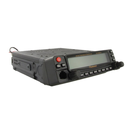
Thanks for buying the
KG-UV920P-E mobile radio.
This mobile radio offers latest design, enhanced features, solid performances and
easy accessibility. We believe you will be pleased with the high quality and reliable
features for all your communication needs.
Read this important information on the safe and efficient operation before using
mobile radio.This manual is suitable for KG-UV920P-E.
Advertisement
Table of Contents

Related Manuals for Wouxun KG-UV920P-E


Summary of Contents for Wouxun KG-UV920P-E
- Page 1 This mobile radio offers latest design, enhanced features, solid performances and easy accessibility. We believe you will be pleased with the high quality and reliable features for all your communication needs. Read this important information on the safe and efficient operation before using mobile radio.This manual is suitable for KG-UV920P-E.
-
Page 2: Safety Information
Safety information Twin Band FM Transceiver The KG-UV920P-E is an electrical apparatus, as well as a generator of RF(Radio Frequency) energy, and you should EU Regulatory Conformance exercise all safety precautions as are appropriate of this type of device. These safety tips apply to any device installed in a As certified by the qualified laboratory, the product is in compliance with the essential requirements and other well-desi-gned amateur radio station. - Page 3 If they do not function normally, please get in touch with the dealer immediately. Back panel If you use components or accessories not sold by Wouxun Company, Wouxun will not guarantee the safety and Side panels usability of the transceiver. Hand microphone...
- Page 4 Contents 28-33 Hotkey function guide Editing a channel name (CH-NAME) ----- Menu 22 Menu operations 33-50 Priority channel switch (PRICH-SW) ----- Menu 23 Step frequency settings (STEP) ----- Menu 1 Speaker settings (SPK- CONT) ----- Menu 24 Wide/Narrow bandwidth settings (W/N) ----- Menu 2 Keypad autolock (AUTOLOCK) ----- Menu 25 Two medium level power settings (MPOWSET) ----- Menu 3 Receiving CTCSS (RX-CTC) ----- Menu 26...
-
Page 5: Checking The Equipment
Turning on Tuning radio stations Standard Accessories Storing and calling out FM radio stations Exiting the FM radio mode Repeater usage KG-UV920P-E Rx CT Rx CT Repeater PTT option BUSY BUSY Repeater SPK option Cross-band repeater entry and exiting... - Page 6 Frequency Range Suitable for any Both Stations can Form Combined Same Region of any Country: Band or Different Band Repeat (RX / TX) 136-174MHz & 400-470MHz High Output Power ( VHF:50W / UHF:40W ) • • 136-174MHz & 400-480MHz CTCSS / DCS Encode / Decode •...
- Page 7 Pre-use installation Transceiver installation Use every screw slot along the side of the support bracket, you can set the transceiver to be insta- Choose a safe place inside your vehicle, one which would to the greatest extent reduce possible harm lled at a different angle.
-
Page 8: Connecting Power Source
Connecting power source Antenna connection The transceiver power source usage ranges from 13.8V±15%. When your power source (or vehicle power Before operation, you must effectively install and adjust the antenna, installation success depends upon source) reaches levels up to 16V, TX will be forbidden, however RX will operate as normal. When your the type of antenna and whether or not the antenna is set up correctly. -
Page 9: Front Panel Installation
Front panel installation The transceiver is supplied with two kinds of switchboard panels•Inclined switchboard panel and a flat Install flat switchboard panel switchboard panel. •1•Lower alignment •2•Cover alignment •3•Close in the direction •4•Use the supplied screws Install inclined switchboard panel shown by arrows to fasten •1•Lower alignmen... -
Page 10: Installation Of Front Panel
Front panel installation Connection method for transceiver station to operating front panel• Special Reminder The vehicle transceiver connection line uses 8 facets and 8 lead conducting wires (diagram 1), If the connection wires are not Company supplied or dealer approved, Company does not guarantee its safety and operational effectiveness! Diagram 1 Dismantling the front panel and transceiver... -
Page 11: Outer Speakers
Getting started •2•First string the connection line through opening in the center of the support bracket•then close the bracket cover directly Front panel as shown by the arrows. KG-UV920P-E Outer speakers QT DT MEMCH The external speaker jacks can be connected to a 3.5mm single outlet. There are two speaker outlets located on the back of the transceiver.
Need help?
Do you have a question about the KG-UV920P-E and is the answer not in the manual?
Questions and answers