
Related Manuals for Akai DPS12


Summary of Contents for Akai DPS12
- Page 1 WARNING To prevent fire or shock hazard, do not expose this appliance to rain or moisture. Operator’s Manual...
- Page 2 WARNING!! To prevent fire or shock hazard, do not expose this appliance to rain or moisture. 1-En CAUTION RISK OF ELECTRIC SHOCK DO NOT OPEN CAUTION: TO REDUCE THE RISK OF ELECTRIC SHOCK, DO NOT REMOVE COVER (OR BACK). NO USER-SERVICEABLE PARTS INSIDE. REFER SERVICING TO QUALIFIED SERVICE PERSONNEL.
- Page 3 Use only a household AC power supply. Never use a DC power supply. • If water or any other liquid is spilled into or onto the DPS12, disconnect the power, and call your dealer. • Make sure that the unit is well-ventilated, and away from direct sunlight.
- Page 4 WARNING WARNING THIS APPARATUS MUST BE EARTHED IMPORTANT This equipment is fitted with an approved non-rewireable UK mains plug. To change the fuse in this type of plug proceed as follows: 1) Remove the fuse cover and old fuse. 2) Fit a new fuse which should be a BS1362 5 Amp A.S.T.A or BSI approved type. 3) Refit the fuse cover.
- Page 5 27-En COPYRIGHT NOTICE The AKAI DPS12 is a computer-based device, and as such contains and uses software in DISKs and ROMs. This software, and all related documentation, including this Operator’s Manual, contain proprietary information which is protected by copyright laws. All rights are reserved. No part of the software or its documentation may be copied, transferred or modified.
- Page 6 If the warranty is valid, AKAI will, without charge for parts or labor, either repair or replace the defective part(s). Without a valid warranty, the entire cost of the repair (parts and labor) is the responsibility of the product's owner.
-
Page 7: Table Of Contents
Chapter 2: Recording on the DPS12 ........20 Connections ........................20 Preparing to record ......................22 Turning on the power to the DPS12 ................ 22 Formatting a JAZ disk ....................22 Creating a new Project .................... 24 MAIN screen and TRACK VIEW screen ................25 MAIN screen ...................... - Page 8 Table of contents Chapter 3: Transport/Locate operation ........39 Transport operation ......................39 Transport button operation ..................39 Using the [JOG] dial and the [SHUTTLE] dial ............39 Using [TO] key and [FROM] key ................41 Locate operation ......................42 Storing locate points ....................
- Page 9 Table of contents When “STEREO” is selected: ................... 66 Send pan setting (AUX SEND PAN) ................. 66 Send level setting (AUX SEND LEVEL) ..............66 Selecting PRE/POST (AUX PRE/POST) ..............67 Other settings ........................ 67 Channel ON/OFF (CHANNEL) ................67 SETUP ........................
- Page 10 Chapter 12: MIDI applications ..........109 Synchronizing an external device to the DPS12 (MTC) ..........109 Synchronizing an external device to the DPS12 (MIDI Clock) ........110 Synchronizing the DPS12 to an external device (MTC) ..........113 Controlling the DPS12 remotely from an external device (MMC) ........114 Recording and playing back a scene memory of the mix parameters ......
- Page 11 Table of contents STEREO FLANGER (G) ..................129 XOVER FLANGER (G) ................... 130 PAN FLANGER (G) ....................130 MONO PHASER (I) ....................131 STEREO PHASER (I) ....................131 XOVER PHASER (I) ....................131 PAN PHASER (I) ....................132 PITCH SHIFT (I) ....................132 ROTARY SPEAKER (I) ....................
-
Page 13: Chapter 1: Outline Of The Dps12
Chapter 1: Outline of the DPS12 This chapter describes the features of the DPS12 and the name of its parts and functions. It also describes the DPS12’s unique conceptual design and operating method. Akai recommends that you read this chapter thoroughly even though you may already be quite familiar with multitrack recorders and mixing consoles. -
Page 14: Parts And Functions
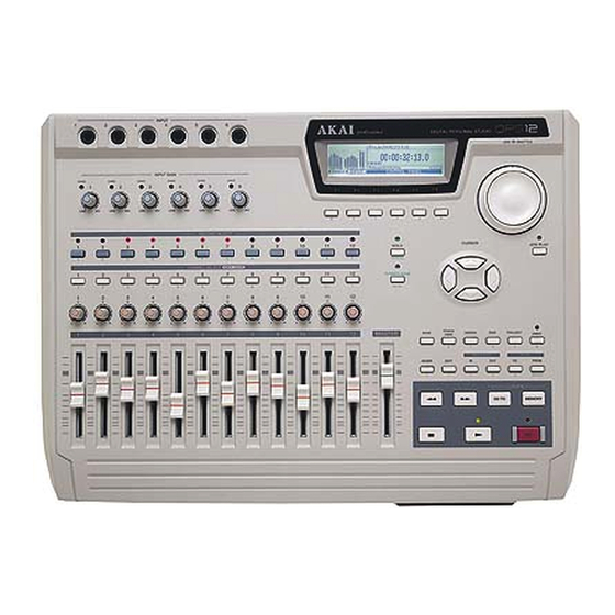
Chapter 1: Outline of the DPS12 Parts and functions This section describes the part names and functions. The names of the controls on the top panel are shown in brackets [ ]. Top panel INPUT INPUT GAIN OVER OVER OVER... - Page 15 These faders control the level of TRACK MIX channels. DIGITAL PERSONAL STUD 8 Display This LCD display indicates various information required for operating the DPS12, such as the time counter and level meter. 9 Function keys ([F1] – [F6]) These keys are used to execute or turn on/off the functions that appear on the bottom row of the display.
- Page 16 These keys are used to store the locate point (the position information in a song) and move the current position on the DPS12 to any locate point. U Transport buttons These keys are used to control the transport operation of the DPS12, such as recording, playback, stop, etc. Each button has the following function: •...
-
Page 17: Front Panel
Chapter 1: Outline of the DPS12 • ] button .... This button is used to rewind. Pressing this button while the transport section is stopped causes the time counter on the display to count backward at high speed. Pressing and holding down this button during playback causes fast reverse playback for as long as you hold it down (Review). -
Page 18: Using An Optional Jaz Drive
Using a JAZ drive If you have a JAZ drive installed on the DPS12, you can store audio data and other information on a JAZ disk inserted in the drive’s slot. A JAZ disk is a storage medium with a capacity of 1 GB, and can accommodate audio data of up to three hours sixteen minutes (at a sampling rate of 44.1kHz in monaural). -
Page 19: Notes On Using An Optional Jaz Drive
JAZ disk or loss of data caused by a forced eject operation. Notes on using a JAZ drive • To be able to use a JAZ disk on the DPS12, you need to format a disk first. (Refer to page 22, 106 for informa- tion on how to format a disk.) •... -
Page 20: About External Scsi Devices
NOTES : • Some models of external SCSI devices may not be compatible with the DPS12. Also, you may not be able to record or playback, or you may have only a limited number of tracks available for simultaneous multitrack recording and playback. - Page 21 Install a terminator on the last SCSI device in the daisy chain. (If the SCSI device has a built-in active termina- tor, turn it on.) The default SCSI ID of the JAZ drive is set to 4 and the SCSI ID of the DPS12 is set to 6.
-
Page 22: About Projects
The internal hard disk can store multiple Projects. However, the DPS12 can handle only one Project at a time. When the power to the DPS12 is turned on, the DPS12 reads the first Project in the disk. You may want to specify another Project on the disk to be read or create a new Project, if necessary. -
Page 23: Track Mix Channels And Thru Mix Channels
MIX channels are useful when you wish to overdub external sound sources while playing back twelve tracks in the recorder section. The following diagram shows a basic signal flow. When the DPS12 is in default status, use the TRACK MIX channels to record and mix down data. - Page 24 Chapter 1: Outline of the DPS12 Analog signal Digital signal Mixer section INPUT THRU MIX channel (ANALOG) GAIN LEVEL GAIN LEVEL GAIN LEVEL GAIN LEVEL GAIN LEVEL GAIN LEVEL LEVEL LEVEL Recorder OPTICAL IN section (DIGITAL) TRACK MIX channel LEVEL...
- Page 25 Chapter 1: Outline of the DPS12 A B L R SOLO LEVEL MIXER INPUT THRU GAIN MIXER ASSIGN INPUT 1 (analog) THRU EQ THRU SEND A THRU PRE/POST SEND B INPUT 2 (analog) PRE/POST SEND A LEVEL INPUT 3 (analog)
-
Page 26: About A Scene Memory
About a scene memory The DPS12 can store a set of mix parameter settings as a scene, and recall the scene later. A scene is stored as part of the Project in the disk. You can store multiple scenes in one Project. For example, you may store multiple scenes with different balance and EQ settings for mixdown, and audition and compare different mixes. - Page 27 Press one of [F3] – [F6] keys. ↓ Control Panel The Control Panel screen is used to set various parameters on the DPS12. Pressing a mode key after the setting is complete will take you to the corresponding mode screen.
- Page 28 Chapter 1: Outline of the DPS12 Field and cursor The parameter values that are shown on the display and that can be modified are called “fields.” The high- lighted part of the screen is called the “cursor.” The field currently highlighted by the cursor indicates that the field is selected for editing.
-
Page 29: Changing A Setting Or A Value
Chapter 1: Outline of the DPS12 Window When you press the key, key, or key, a window appears on the screen. [UNDO] [GO TO] [MEMORY] A window is used to make a setting or operate a function that varies depending on the key you pressed. As you do in a normal screen, you can change the parameter settings by moving the cursor to the desired parameter, or use the function keys to execute the desired function. - Page 30 Chapter 1: Outline of the DPS12 Entering a numeric value directly (time counter/time field) You can use the keys on the top panel to directly enter a value for the time counter, and time field on the MAIN screen. Follow the steps below: 1.
- Page 31 Chapter 1: Outline of the DPS12 4. Use the [CURSOR] key or the [SHUTTLE] dial to move the underline to the second character position. While the key’s LED is flashing, you can move the underline back and forth using the...
-
Page 32: Chapter 2: Recording On The Dps12
CAUTION : Make sure that you turn off the power to all equipment before making connections. DIGITAL OUT jacks on AKAI sampler are of the coaxial type. You will need an optical converter to NOTE : connect a sampler to input digital signals to the DPS12. - Page 33 If you use a master recorder that has digital input jacks, such as a DAT recorder or an MD recorder, connect the OPTICAL OUT jacks of the DPS12 to the digital input jacks of the master recorder, and the output jacks of the master recorder to the monitor system.
-
Page 34: Preparing To Record
Do not insert a JAZ disk into the JAZ drive on the front panel before you turn on the power to the DPS12. If you turn the power on or off while a JAZ disk is inserted in the drive, the disk may be damaged and recorded data may be lost. - Page 35 SCSI device, such as a hard disk or an MO drive is connected to the SCSI connector of the DPS12, make sure that the SCSI ID field in this screen is set to “4” (internal JAZ drive) so that you will not erase important data from other disks.
-
Page 36: Creating A New Project
Chapter 2: Recording on the DPS12 Creating a new Project Since the DPS12 requires that at least one project exists on the current disk for recording, the following window for creating a new Project automatically appears when the format operation is complete. -
Page 37: Main Screen And Track View Screen
MAIN screen The MAIN screen is a start point for various operations on the DPS12. When you turn on the power to the DPS12, this screen always appears if a formatted disk (that contains a Project) is in the disk slot. The following informa- tion is included in the MAIN screen. -
Page 38: Track View Screen
TRACK VIEW screen Pressing the key while the MAIN screen is displayed will cause the DPS12 to enter TRACK [TRACK VIEW] VIEW mode, and the TRACK VIEW screen will appear. In this screen, data in each track is represented by a bar graph, if any, and the range between the IN point and the OUT point (used to specify the range for the Auto Punch In/Out operation or the edit functions) is highlighted. -
Page 39: Recording The First Track
Track 9 Track 10 Track 11 Track 12 Recording signal flow 1 With the DPS12’s default settings, signals input at INPUT jacks 1/2 are sent via controls to [INPUT GAIN] physical tracks 1/2 of the recorder section. 2 Press the... -
Page 40: Recording To The First Track
[RECORD SELECT] key (and its LED flashes in red), the corresponding track enters record ready mode. The type of signal output from each track varies depending on the status of the DPS12 and the status of the key for each track. - Page 41 3: Transport/Locate operation.” 9. Press the [ ] key to start playback from the top of the song. When the DPS12 play back data, you can monitor the recorder’s playback sound through any track, regardless of the on/off status of their keys.
-
Page 42: Using A Locate Point
4. Repeat Steps 2–4 until necessary quick locate points are all stored. 5. To locate the stored quick locate point, press the [GO TO] key when the DPS12 is stopped. The LOCATE LIST window appears where you can perform the locate operation. -
Page 43: Overdubbing
MASTER Track 10 Track 11 Track 12 Overdubbing signal flow 1 With the DPS12’s default settings, signal input at the INPUT jacks 3 is sent via controls to [INPUT GAIN] physical track 3 of the recorder section. 2. Press the key 3 on the top panel to place track 3 in recording ready status. -
Page 44: Overdub Operation
If you are not satisfied with a recording, you can use the Undo function to cancel the previous recording. With the DPS12’s default setting, the undo level is set to “1.” (The undo level is a parameter that determines the number of previous operations you can undo. -
Page 45: Undo Level = 2 Or Higher
The Punch In/Out function enables you to re-record only a specified region on an already-recorded track. The DPS12 offers a “Manual Punch In/Out function” that uses the transport keys and a foot switch, and an “Auto Punch In/Out function” that automatically performs the punch in/out operation at specified positions. In this example, we will modify part of the bass guitar performance recorded on track 3, using the Auto Punch In/Out function. - Page 46 5. Press one of the [F3] – [F6] keys while the MAIN screen is displayed. The Control Panel appears, where you can make various settings for the DPS12. 6. Make sure that the AUTO PUNCH Control Panel shown above appears on the display. If another Control Panel appears, turn the [JOG] dial to recall the AUTO PUNCH Control Panel.
-
Page 47: Mixdown
Chapter 2: Recording on the DPS12 12. Press the [ ] key to stop playback. TIPS : • When you punch out, the AUTO PUNCH field of the AUTO PUNCH Control Panel is automatically set to off. If you are going to perform the punch in/out operation repeatedly, it is convenient to have this Control Panel displayed all the time during the operation. -
Page 48: Mixdown Procedure
TRACK MIX channels 1–12 of the mixer section. However, the mixer section offers more mix parameters. For example, each of the TRACK MIX channels 1–12 has a two-band EQ (DPS12’s default setting) and the AUX send A/B parameters. These mix parameters are controlled in Mixer mode. This section explains how to use Mixer mode during mixdown. - Page 49 [F3] key and the [F4] key to select a mix parameter. The following mix parameters can be selected when the DPS12 is set to default. • EQ HIGH FREQ (base frequency of high range) • EQ HIGH LEVEL (level of high range) •...
-
Page 50: Completing The Operation On The Dps12
Be sure to eject a JAZ disk from the JAZ drive before you turn off the power to the DPS12. CAUTION : If you turn off the power to the DPS12 while a JAZ disk is inserted in the drive, the disk may be damaged. 2. Turn off the power to the devices in the following order: monitor system... -
Page 51: Chapter 3: Transport/Locate Operation
Chapter 3: Transport/Locate operation Chapter 3: Transport/Locate operation This chapter describes the transport and locate operations of the DPS12. Transport operation You may perform locate operations and shuttle playback using the [JOG] [SHUTTLE] dials, and part playback using the keys, as well as the usual transport operations using the transport buttons. - Page 52 Chapter 3: Transport/Locate operation 1. Press the [JOG PLAY] key on the top panel. [JOG PLAY] key’s LED lights up and the transport section enters Jog Play mode, in which you can perform the jog/shuttle playback. The screen displays the waveform of the data in the selected track. The selected number appears in the upper right corner of the screen.
-
Page 53: Using [To] Key And [From] Key
Stops. Pressing the key during the TO playback operation will cause the DPS12 to continue TIP : [FROM] playing back skipping over the NOW point. (That is, the DPS12 will play back the amount of “To time” + “From time.”) -
Page 54: Locate Operation
You may specify up to 100 points (locate points) in a song and store them in a locate list to help you locate points quickly. The DPS12 also features a Quick Locate function that enables you to assign a locate point to a key on the panel and locate the point with a simple key operation. -
Page 55: Moving To A Locate Point
Locating the zero position of the time counter When the LOCATE LIST window is displayed, the DPS12 can also locate the zero position of the time counter (zero return). If the time counter indicates the ABS value (absolute time value), the time position at the top of the Project is located. -
Page 56: Locating The End Point Of A Song
Deleting a locate point from the locate list You can delete a locate point stored in the locate list as follows: 1. Make sure that the MAIN screen is displayed and the transport section of the DPS12 is stopped. 2. Press the [GO TO] key. -
Page 57: Repeat Function
The LOCATE LIST window appears. 2. Press one of the [CHANNEL SELECT] 1–12 keys or the [IN] or [OUT] key. The DPS12 locates the point stored in the key you pressed and the window closes. Repeat function Repeat function plays back data between the IN point and the OUT point. -
Page 58: Using The [In] And [Out] Keys To Play Data Between The [In] Point And The [Out] Point
This is useful when you wish to check the position of the auto punch in/out points or a range to be edited. 1. Make sure that the transport section of the DPS12 is stopped. 2. Press the [IN] key or the [OUT] key. -
Page 59: Entering A Time Value In The Counter
6, the time counter indicates the numbers in the following order. 3. When you finish entering the value, press the [NUMBER/NAME] key again. The DPS12 locates the position that corresponds to the time value. Press the ) key to cancel the entered value. -
Page 60: Chapter 4: Punch In/Out
[REC] recording track changes to that of the input source (currently recording performance). If the REHEARSAL parameter on the Control Panel has been turned on, the DPS12 enters TIP : “Rehearsal mode” in which you can practice the punch in operation before you record a real punch in take. -
Page 61: Punch In/Out Operation Using A Foot Switch
With the exception of performing the punch in/out operation with a foot switch, the operation of the DPS12 itself is the same as the punch in/out operation using the transport buttons. -
Page 62: Auto Punch In/Out
The monitor signal through the recording track changes to that of the input source (the currently- recording performance). If the REHEARSAL parameter on the Control Panel has been turned on, the DPS12 enters TIP : “Rehearsal mode,” in which you can practice the punch in operation before you record an actual punch in take. -
Page 63: Punch In/Out Rehearsal
LED continuous to [REC] flash flashing, and no signal is recorded in the record-ready track. When the counter reaches the OUT point time, the DPS12 resumes normal playback. 7. Press the [ ] button to stop playback. IN point OUT point •... -
Page 64: Chapter 5: Assigning Input Signals And Virtual Tracks (Assign Mode)
About Assign mode When the DPS12 is set to default, signals input at INPUT jacks 1–6 on the top panel are distributed to physical tracks 1–6 and 7–12 of the Recorder section. Physical tracks 1–12 are assigned to virtual tracks 1–12. In Assign mode, you can change the assignments of input signals and virtual tracks. - Page 65 Chapter 5: Assigning Input Signals and Virtual Tracks THRU MIX With the setting, the input signal is routed directly to the THRU MIX channels of the mixer section. Use this setting when you wish to add an analog input signal or a digital input signal to the 12-track playback sound.
-
Page 66: Assigning Input Sources To Tracks (Source)
Track 12 For example, when the DPS12 is set to default and you wish to record the sound of a synthesizer connected to INPUT jacks 1 and 2, you need to re-patch the synthesizer to INPUT jacks 3 and 4. However, if you assign INPUT jacks 1 and 2 to tracks 3 and 4, you can record the synthesizer sound to tracks 3 and 4 without re-connect- ing the instrument. - Page 67 Chapter 5: Assigning Input Signals and Virtual Tracks Follow the procedure below to assign input signals to tracks: 1. Use the [CURSOR] key to move the cursor up and down and select a track for which you wish to change the input signal assignment. Example: Track 3 is selected and analog INPUT jack 3 has been assigned to that track.
-
Page 68: Assigning A Virtual Track To A Physical Track
Chapter 5: Assigning Input Signals and Virtual Tracks Assigning a virtual track to a physical track Pressing the key in Assign mode causes the following screen to appear. In this screen, you can assign [F4] V.TRK up to 250 virtual tracks to physical tracks 1–12. 1 This select field allows you to select one of the 250 virtual tracks. -
Page 69: Track Erase Function
NOTES : • When the DPS12 is set to default, virtual tracks 1–12 are assigned to physical tracks 1–12. • You cannot assign a single virtual track to multiple physical tracks. For example, if virtual track 1 has already been assigned to physical track 1, you cannot assign virtual track 1 to another physical track. -
Page 70: Chapter 6: Mixer Function (Mixer Mode)
[F5] key/[F6] key parameter. Basic operation in Mixer mode You can use the faders and controls on the DPS12 to adjust the TRACK MIX channel’s level and pan settings. To adjust other mix parameter settings, follow the steps below. TRACK THRU 1. - Page 71 Chapter 6: Mixer Function TRACK If you press the [F1] key, TRACK MIX channels are selected and the level meters indicate the output level of each track. THRU If you press the key, THRU MIX channels are selected and the level meters indicate the input level [F2] of INPUT jacks.
- Page 72 Chapter 6: Mixer Function If you press multiple [CHANNEL SELECT] keys simultaneously, you can select the corresponding channels at once. Example: TRACK MIX channels 3 and 4 are selected. TIPS : • You can use the [CURSOR] key to move the cursor to the graphical field of a desired channel, instead of using the key to select the channel.
-
Page 73: Level/Pan Settings
Chapter 6: Mixer Function Level/pan settings LEVEL You can adjust the input level of each channel (LEVEL) and the master output level (MASTER). Range: 0–127 When TRACK MIX channels are selected: When THRU MIX channels are selected: TIPS : • Since the channel faders on the top panel always allows you to adjust the TRACK MIX channel level, you can use the faders to set the track level even when the THRU MIX channels are selected. -
Page 74: Equalizer Settings
Chapter 6: Mixer Function Equalizer settings You can set the parameters for the 3-band (HIGH – shelving type, MID – peaking type, and LOW – shelving type) equalizer. You can use the 3-band equalizer for up to six channels. If you wish to apply equalization to all NOTE : twelve channels, switch to the 2-band (HIGH, LOW) equalizer. -
Page 75: Setting The Level (Eq High/Mid/Low Level)
Chapter 6: Mixer Function While this screen is displayed, the [F5] key and the [F6] key function as follows: ON/OFF • ..switches EQ on/off for the selected channel. To check the on/off status of the selected [F5] key channel EQ, select the EQ ON/OFF parameter (see page 62). STRIP •... -
Page 76: Displaying All Eq Parameters Of A Given Channel (Strip)
[JOG] AUX send settings AUX type The DPS12 provides a two-channel AUX send. You can set the SETUP: parameter to select whether 2 MONO STEREO the AUX send signals are two-channel monaural signals ( ) or a pair of stereo signals ( ). -
Page 77: Selecting Pre/Post (Aux A (B) Pre/Post)
Chapter 6: Mixer Function Mixer section Analog signal Digital signal Routing the signal to AUX send A LEVEL SEND A PRE/POST SEND A Level Routing the signal to AUX send B LEVEL SEND B PRE/POST SEND B EB2M Level SEND A Master level EFFECT A AUX SEND A... -
Page 78: When "Stereo" Is Selected
Chapter 6: Mixer Function When this screen is displayed, the [F5] key and the [F6] key function as follows: EFFECT • ..Recalls the screen used to set the internal effects. (Needs optional EB2M) [F5] key SCENE • ..Recalls the SCENE MEMORY window used to store and recall a scene memory. [F6] key When “STEREO”... -
Page 79: Selecting Pre/Post (Aux Pre/Post)
Chapter 6: Mixer Function When this screen is displayed, the [F5] key and the [F6] key function as follows: EFFECT • ..Recalls the screen used to set the internal effects. (Needs optional EB2M) [F5] key SCENE • ..Recalls the SCENE MEMORY window used to store and recall a scene memory. [F6] key Selecting PRE/POST (AUX PRE/POST) This parameter sets whether the channel signal sent to AUX send is routed from the pre-fader position (PRE) or... -
Page 80: Setup
Chapter 6: Mixer Function SETUP These parameters enable you to select the type of EQ and AUX. To change the setting, use the key to [CURSOR] move the cursor to the desired field and turn the [JOG] dial. EQ type: This select field enables you to select a type of EQ. -
Page 81: Scene Memory
Chapter 6: Mixer Function SCENE MEMORY In Mixer mode, you may name the mix parameter settings, such as LEVEL, EQ, and PAN, and store them in a scene memory. A stored scene can be recalled any time the transport section is stopped. A scene is stored in the disk as part of the project. -
Page 82: Erasing A Scene
RECALL 2. Press the [F4] key. The scene is recalled, and the DPS12 returns to the last Mixer mode that was obtained before you recalled the scene memory. NOTES : • When you recall a scene, the current Mixer parameter settings are replaced with those in the recalled scene. -
Page 83: Chapter 7: Advanced Technique For Mixing
THRU 2. Press the [F2] key in Assign mode. The DPS12 displays a screen in which you can route input signals to the recorder section as input sources or to the THRU MIX channels of the mixer section. Analog In-1... -
Page 84: Mixing Several Inputs Via Aux
THRU 2. Press the [F2] key in Assign mode. The DPS12 displays a screen in which you can route input signals to the recorder section as input sources or to the THRU MIX channels of the mixer section. Analog In-1... -
Page 85: Digital Input From An External Device
8. Adjust the level, PAN, and EQ for each channel. Play the DPS12 and adjust the level and PAN of the playback sound for TRACK MIX channels 1 and 2. Then, set the level and PAN of AUX SEND for THRU MIX channels 1–6. -
Page 86: Using The Solo Function
Using the Solo function The mixer section of the DPS12 provides a Solo function that allows specified channels to be routed to Master L/ R. This function is useful when you wish to monitor only certain input signals or tracks. The Solo function is available whenever the transport operations on the DPS12 are available (that is, in Main mode, Track View mode, Mixer mode, and when the Control Panel is displayed). - Page 87 LED turns off and the Solo function is cancelled. [SOLO] TIP : The DPS12 memorizes the solo channels you select using the [RECORD SELECT] keys during the Solo operation and retains them until the power to the unit is turned off. When you turn on the Solo...
-
Page 88: Using Virtual Tracks
[F4] key in Assign mode before you start recording the first guitar solo take. V.TRK The DPS12 displays a screen where you can assign up to 250 virtual tracks to twelve physical tracks. With the default setting, the DPS12 assigns virtual tracks 1–12 to physical tracks 1–12. Tracks that already V.Track... -
Page 89: Digital Ping-Pong Recording
1–10 signals into stereo and ping-pong record to physical tracks 11–12. 1. While playing back data on the DPS12, use the channel faders 1–10 and [PAN] controls to adjust the level and panning for TRACK MIX channels 1–10. If necessary, select TRACK MIX channels in Mixer mode to set the EQ and other mix parameters. -
Page 90: Using An External Effect Unit For Mixdown
1. Connect the AUX SEND A jack of the DPS12 to the input jack of an external reverb effect unit, and connect the output jack of the reverb effect unit to INPUT jacks 1 and 2 of the DPS12. At this time, make sure that the reverb effect unit outputs only the effect sound (reverb sound). -
Page 91: Adding Sounds During Mixdown
Send signals from INPUT jacks 1–6 and/or the OPTICAL IN jacks to THRU MIX channels to mix with TRACK MIX channels. For example, if you have a MIDI sequencer sync with the DPS12, you can mix up to eight channels of signals from synthesizers or samplers. -
Page 92: Chapter 8: Edit Technique (Edit Mode)
Chapter 8: Edit technique (Edit mode) The DPS12 provides various editing capabilities in Edit mode. You can specify a range of audio data in a physical track to copy to a different position or another track. You can also delete the specified portion of data. For ex- ample, you may use the same chorus or guitar phrase repeatedly, or you may move all track data to a different position to change the structure of the song. -
Page 93: Basic Operations In Edit Mode
3. Press the [EDIT] key when the DPS12 is stopped. The DPS12 enters Edit mode. The settings made in Steps 1 and 2 are reflected in the In, Out, and NOW point fields on the screen. NOW point... -
Page 94: Type And Function Of Edit Commands
Chapter 8: Edit technique 6. Use the [CHANNEL SELECT] key and the [RECORD SELECT] key to select a FROM track and a TO track (or EDIT track). The selected tracks appear as follows on the screen. Example: This setting is used to cut Track 2 and paste it to Track 1 99 times. DO IT 7. -
Page 95: Copy Insert
Chapter 8: Edit technique • If the number of TO tracks is smaller than the number of FROM tracks, the edit command will be executed for the number of TO tracks in the order of the FROM track number. FROM track TO track Track 1 Track 1... -
Page 96: Cut Paste
Chapter 8: Edit technique PASTE This command enables you to cut (delete) data between the IN point and OUT point, and paste the data after the NOW point. Silence will be created between the IN and OUT point, and the existing data in the destination will be overwritten. -
Page 97: Cut Discard
Chapter 8: Edit technique DISCARD This command enables you to cut data between the IN point and OUT point. The data is deleted and replaced with a silence. IN point OUT point IN point OUT point EDIT track Silence DISCARD MOVE This command enables you to cut data between the IN point and OUT point. -
Page 98: Chapter 9: Control Panel
This chapter describes the functions and operations of the Control Panel used for the setting of the DPS12 operation. Basic operation of the Control Panel The Control Panel is a screen in which you can set various internal parameters related to the DPS12 operation. To CONTROL PANEL recall the Control Panel, press the –... -
Page 99: Vari Pitch
This function utilizes parameters to adjust the recording and playback speeds. The DPS12 provides a Vari Pitch function that enables you to change recording and playback speeds. You can set the speed variation and on and off in this screen. -
Page 100: Time Display (Setting The Time Counter Display)
BAR.BEAT.CLOCK When is selected NOTE : Changes in this parameter value will be reflected on all time indications on the DPS12. While you are synchronizing a MIDI sequencer to the MIDI clock transmitted from the DPS12, TIP : BAR.BEAT.CLOCK selecting will allow you to specify the locate points and/or edit points in steps of measures and beats. -
Page 101: Time Offset (Offset Of Relative Time)
(Relative time) This display indicates the current position of the DPS12 in relative time. A relative time value is obtained by subtracting an offset value from the absolute time (ABS). Move the cursor to this field, and use the... -
Page 102: To/From Time (Time Settings For The [To] Key And [From] Key)
PLAY MONITOR (selecting a monitoring source during playback) You can select track monitor source during playback. While the DPS12 is playing, you can switch between input signals and track playback signals to monitor physical tracks that have their keys turned on. -
Page 103: Sync (Synchronization)
2 SYNC ON/OFF [F6] key (Sync on/off) This select field enables you to switch the sync operation on and off. When this field is set to OFF , the DPS12 does not transmit or receive any sync signal, regardless of the settings 1. Use the... -
Page 104: Sampling Rate
When the digital input signal is used, match the sampling rate to that of an external device. Digital sync This field enables you to select whether the DPS12 operates in reference to the internal clock or to an external digital clock. Use the... -
Page 105: Tempo Map
DPS12, the tempo settings of the MIDI sequencer are ignored. Therefore, you need to specify the tempo of the MIDI clock on the DPS12. In this Control Panel, you can enter tempo information (the number of quarter notes played in a minute) at the point where the tempo changes. The parameters and function keys include the following functions. -
Page 106: Foot Switch
........... The MIDI OUT/THRU jack functions as a MIDI OUT jack. NOTE : If you use the DPS12 as a sync master device to send MTC or MIDI clock to an external device, you need to set this parameter to LCD CONTRAST You can adjust the contrast of the LCD display. -
Page 107: Other (Other Setting)
Chapter 9: Control Panel OTHER (other setting) You can set parameters related to the level meters and the Undo function. In this Control Panel, you can toggle between pre and post faders for the level meter indication, and set how many previous operations can be restored by the Undo function. -
Page 108: Chapter 10: Project Management (Project Mode)
• Protect on/off You can store multiple Projects on a disk, but the DPS12 can handle only one Project at a time. The project being processed on the DPS12 is called the “current Project.” If a disk does not have enough space to accommodate Projects, you may erase unnecessary Projects from the disk, or back-up data to an external SCSI device or DAT recorder. -
Page 109: Creating A New Project
TIP : [F2] NOTES: • When you format a disk, the DPS12 automatically displays the NEW PROJECT window. • When you create a new Project, the previous Project is automatically stored. You can recall it at any later time. TIP :... -
Page 110: Recalling A Project
NOTE : When you turn on the power to the DPS12 and load data from the disk, it will automatically recall the first Project (a Project you accessed for the last time) in the Project list stored in the disk. -
Page 111: Backing Up A Project To An External Device
5. Select whether you wish to format the backup disk in the select field 4. If you select FORMAT in the Format Operation field, the DPS12 formats the disk, then backs up the data. If you select ERASE , the DPS12 backs up data without formatting the disk. - Page 112 • You cannot directly access backup data on an external SCSI device directly. You must first load the backup data into the DPS12. See page 99. If you wish to make a copy of the Project that you can access directly, use the Copy function in Disk mode.
-
Page 113: Reloading The Backup Project
Chapter 10: Project management 3. Move the cursor to the select field 1 and select DAT . 4. Move the cursor to the select field 2 and select a Project for backup. 5. Move the cursor to the select field 3 and select a sampling rate for recording on the DAT recorder ( 32kHz , 44.1kHz , 48kHz ). - Page 114 DO IT 3. Press the [F5] key. The DPS12 waits for the data to be loaded. 4. Play the DAT tape that contains the backup data. When the reload operation is complete, the display returns to the PROJECT screen. Do not monitor the audio via the DAT during the backup operation. Since audio and other CAUTION : data is transmitted as a digital signal, an attempt to monitor it may damage the speakers.
-
Page 115: Chapter 11: Using A Disk (Disk Mode)
Removable disks, such as JAZ disks, will not be detected until they are inserted. To use a removable disk as the current disk, insert a disk immediately after you turn the power on. If the DPS12 does not find disk that contains a Project in the SCSI bus, it will continue to search for one while the SKIP start-up screen is displayed. -
Page 116: Changing The Current Drive
NOTE : appears even if an external SCSI device is connected, press the DISK key again. If the same message appears again, turn off the power to the DPS12 and check the connections. REC NOT READY appears if a backup disk (that the DPS12 cannot access directly) is connected. -
Page 117: Viewing The Drive Information
SCSI ID=3 The device with becomes the current drive, and the DPS12 returns to the DISK SETUP screen. NOTES : • When the current drive is changed, the first Project in the Project list stored in the new current drive is automatically recalled. -
Page 118: Formatting A Disk
You may format a current disk using one of the following two methods: format and erase. Formatting is an operation that writes format information to the disk, enabling it to be used on the DPS12. To use a new JAZ disk or an external hard disk, you first need to format it. Also, you may wish to re-format a formatted disk that is causing a write/read error to occur. -
Page 119: Defragmenting A Disk
Chapter 11: Using a disk Defragmenting a disk Repeated recording and edit operations on the DPS12 fragments audio data written on the disk. If this fragmenta- tion is significant, recording or playback may be interrupted. The DPS12 enables you to re-align the fragmented audio data (“defragment”) to solve this problem. -
Page 120: Using A Removable Drive
DO IT 6. Press the [F5] key. After formatting or erasing the destination disk, the copy operation is executed. When the operation is com- plete, the DPS12 returns to the DISK SETUP screen. CANCEL Press the key to cancel the operation. -
Page 121: Chapter 12: Midi Applications
Connecting an external device, such as a MIDI sequencer, to the MIDI IN jack or the MIDI OUT/THRU jack of the DPS12 enables you to synchronize the DPS12 to the MIDI sequencer or record and play back the mix param- eters via the MIDI sequencer. -
Page 122: Synchronizing An External Device To The Dps12 (Midi Clock)
Synchronizing an external device to the DPS12 (MIDI Clock) This example also uses the DPS12 as a sync master. However, sync signals supplied to an external device do not constitute MTC, but MIDI Clock plus Song Position Pointer information. MIDI Clock is timing information in which one beat consists of 24 clocks. - Page 123 Chapter 12: MIDI applications 1. Use a MIDI cable to connect the DPS12’s MIDI OUT/THRU jack and the MIDI sequencer’s MIDI IN jack. MIDI Clock + Song Position Pointer MIDI OUT/ THRU MIDI IN INPUT dps12 DIGITAL PERSONAL STUDIO MIDI sequencer...
- Page 124 11. Move the cursor to the SLCT: field, and turn the [JOG] dial to recall the TEMPO MAP Control Panel. If the DPS12 supplies MIDI Clock to the MIDI sequencer, the tempo setting of the MIDI sequencer will be ignored. Therefore, you need to set the tempo in the TEMPO MAP Control Panel.
-
Page 125: Synchronizing The Dps12 To An External Device (Mtc)
Synchronizing the DPS12 to an external device (MTC) In this example, the DPS12 is used as a sync slave device. MTC (MIDI timecode) is supplied from an external MIDI sequencer or computer-based sequence software to the DPS12, which will synchronize to the MIDI se- quencer operation. -
Page 126: Controlling The Dps12 Remotely From An External Device (Mmc)
DPS12 to remotely select and cancel recording tracks and control the transport section of the DPS12. 1. Use a MIDI cable to connect the MIDI IN jack of the DPS12 and the MIDI OUT jack of an external device. -
Page 127: Recording And Playing Back A Scene Memory Of The Mix Parameters
Change messages. If you record this scene memory to a MIDI sequencer, you can play back the same mix settings each time you play the MIDI sequencer. 1. Use MIDI cables to connect the MIDI IN/OUT jacks of the DPS12 to the MIDI OUT/IN jacks of a MIDI sequencer. -
Page 128: Recording And Playing Back A Mix Automation
9. When transmission is complete, stop the DPS12 and MIDI sequencer. 10. If you wish to send the recorded scene memory back to the DPS12, set the MIDI transmit channel of the MIDI sequencer track (that recorded the Control Change messages) to the same number as the MIDI receive channel of the DPS12 as specified in Step 5. - Page 129 MIDI field and the Tx mixer changes: field respectively. 5. Create a mix beginning at the start position of the song on the DPS12, and follow the instructions under “Recording and playing back a scene memory of the mix parameters” to record the scene memory in the top position of the MIDI sequencer.
-
Page 130: Dps12 Midi Control Change Assign Table
Chapter 12: MIDI applications DPS12 MIDI Control Change Assign Table * If you set AUX type to STEREO, the Control Change numbers are assigned as follows: 41 — 60: AUX LEVEL 61 — 80: AUX PAN... -
Page 131: Chapter 13: Using The Effects
Effect signal flow If you have installed an optional effect board EB2M in the DPS12, you can use two channels of stereo effects: EFFECT A and EFFECT B. Channel signals sent to AUX SEND A and B from the mixer channels are routed to EFFECT A and EFFECT B within the digital domain. -
Page 132: Using Effects For Mixdown
Chapter 13: Using the effects If you are using Insert effects on some channels during mixdown, you do not need to mix a dry sound and an effect sound, since the effect return signal includes a processed sound or a mixture of dry and effect sounds. Therefore, route the channel signal to which you wish to apply effects from the pre-fader position to AUX SEND A/B, and set the LEVEL parameter to 0. -
Page 133: Using Effect Return Signals As Analog Inputs
Chapter 13: Using the effects 5. If necessary, move the cursor to the parameter you wish to adjust in field 2, and turn the [JOG] dial to set the value. TIPS : MORE • The parameters of some effect types are displayed over two screens. In this case, press the [F6] BACK in the first screen to recall the second screen. - Page 134 Chapter 13: Using the effects 1 MIXED STEREO • EFFECT A and B return signals L/R are mixed and routed as analog inputs 5 and 6. You cannot use analog INPUT jacks 5 and 6 to input external signals. ASSIGN FX RTN INPUT 3 GAIN...
-
Page 135: Routing Effect Return Signals To Thru Mix Channels
Chapter 13: Using the effects 1 MIXED If you selected Global effects for both EFFECT A and B, you may want to select TIP : STEREO 2 STEREO PAIRS . If you have selected Insert effects for either EFFECT A or B or both, 2 STEREO PAIRS you may want to select Routing effect return signals to THRU MIX channels... -
Page 136: Adjusting The Effect Return Level
Chapter 13: Using the effects If you selected Insert effects 1. Select TRACK MIX channels in Mixer mode, and adjust the AUX SEND-A or AUX SEND-B level of the channel to which you wish to apply effects. At this time, you can check the output level of AUX SENDs A/B using level meters SA/B. AUX-A PRE/POST AUX-B PRE/POST 2. -
Page 137: Recording Sound To A Track While Applying An Insert Effect
Chapter 13: Using the effects Recording sound to a track while applying an Insert effect You may sometimes wish to record sound with an Insert effect applied via an input. This section describes an example in which we apply a stereo phaser of EFFECT A to the INPUT 1 signal and record on Tracks 5 and 6. THRU 1. - Page 138 Chapter 13: Using the effects EFFECT 5. Press the [F5] key in Mixer mode and select a type of Insert effect. Also, set the other effect parameters, if necessary. FX RTN 2 STEREO PAIRS 6. Press the [F1] key in Assign mode, and select The effect return signals from EFFECT A and B are switched to analog input signals 3/4 and 5/6.
- Page 139 Chapter 13: Using the effects The following diagram illustrates the signal flow when you are using an Insert effect. (Dotted boxes indicate the steps described above.) MIXER mode ASSIGN mode LEVEL THRU LEVEL=0 THRU MIX LEVEL INPUT 1 GAIN (ANALOG) ASSIGN mode MIXER mode SOURCE...
-
Page 140: Effect Type And Parameter
Chapter 13: Using the effects Effect type and parameter This section describes the types and parameter functions of the optional internal effects. Global effects are indicated with (G) and Insert effects are indicated with (I) after their names. When you select an effect type, recommended values appear for the parameters. These settings can be changed, if necessary. -
Page 141: Xover Chorus(G)
Chapter 13: Using the effects XOVER CHORUS(G) This is a variation of the STEREO CHORUS. LFO1 LFO2 Delay Width Fdback Delay inverter LFO1 LFO2 Parameter Setting range Function Rate1 0.1Hz – 10.0Hz Adjusts the speed of LFO1. Rate2 0.1Hz – 10.0Hz Adjusts the speed of LFO2. -
Page 142: Xover Flanger (G)
Chapter 13: Using the effects Parameter Setting range Function Rate 0.1Hz – 10.0Hz Adjusts the speed of LFO. Depth 0 – 127 Adjusts the depth of LFO. Fdback 0 – 127 Adjusts the feedback amount. FB Inv ON/OFF Inverses the phase of feedback signals when turned on. Width 0 –... -
Page 143: Mono Phaser (I)
Chapter 13: Using the effects MONO PHASER (I) This is a common phaser effect. Fdback Phaser Parameter Setting range Function Rate 0.1Hz – 10.0Hz Adjusts the speed of LFO. Depth 0 – 127 Adjusts the depth of LFO. Fdback 0 – 127 Adjusts the feedback amount. -
Page 144: Pan Phaser (I)
Chapter 13: Using the effects PAN PHASER (I) This effect pans the sound image of the mono phaser effect sound to left and right. Fdback autopan Phaser Parameter Setting range Function Rate 0.1Hz – 10.0Hz Adjusts the speed of LFO. Depth 0 –... -
Page 145: Rotary Speaker (I)
This effect simulates rotary speakers. Use external MIDI Control Change messages or the function key on the DPS12 to switch between two rotation speeds (Rate1/Rate2). Rate1 When the DPS12 receives a specified Control Change message, is selected if the value falls between 0 and Rate2... -
Page 146: Trigger Pan (I)
Chapter 13: Using the effects TRIGGER PAN (I) This auto pan effect becomes enabled when the output level of AUX SEND A or AUX SEND B exceeds a certain MANUAL level. You can also press the [F6] key to start the auto pan effect manually. autopan Trigger Parameter... -
Page 147: Panning Delay (G)
Chapter 13: Using the effects PANNING DELAY (G) This delay effect pans the delay sound left, center, then right (LCR), or right, center, then left (RCL). Parameter Setting range Function Delay 1 – 1500ms Adjusts the delay time. Fdback 0 – 127 Adjusts the amount of delay that is fed back. -
Page 148: Tape Echo (G)
Chapter 13: Using the effects Parameter Setting range Function LDelay 1 – 1500ms Adjusts the delay time of the L channel. Fdback 0 – 127 Adjusts the amount of delay that is fed back. HFdamp 20Hz – 20kHz Sets a frequency at which the higher range of the feedback sound is cut. RDelay 1 –... -
Page 149: Reverb>Small Hall (Small Hall Reverb) (G)
Chapter 13: Using the effects Parameter Setting range Function Pre-D 1 – 100ms Adjusts the delay time of early reflections. Time 0.1 – 10sec Adjusts the time of attenuation of reverberation. Diff 0 – 127 Adjusts the density of reverberation. HFdamp 20Hz –... -
Page 150: Reverb>Non-Linear (Non-Linear Reverb) (G)
Chapter 13: Using the effects REVERB>NON-LINEAR (Non-linear Reverb) (G) This reverb effect (gate reverb) stops reverberation at a specified time. Parameter Setting range Function Pre-D 1 – 100ms Adjusts the delay time of early reflections. Hold 0 – 127 Adjusts the time (duration) until reverberation is stopped. Diff 0 –... -
Page 151: Expander (I)
Chapter 13: Using the effects EXPANDER (I) This effect expands (boosts) signals with a certain level or lower and broadens the dynamic range. Parameter Setting range Function Thresh –60dB – 0dB Adjusts the level at which the effect is enabled. Ratio 1:2 –... -
Page 152: Autowah (I)
Chapter 13: Using the effects AUTOWAH (I) This effect adds a swelling wah. Parameter Setting range Function Rate 0.1 – 10.0Hz Sets the speed (rate) of swelling (LFO) of the wah effect. Depth 0 – 127 Sets the depth of the effect. Reso 0 –... -
Page 153: Flange>Delay (G)
Chapter 13: Using the effects FLANGE>DELAY (G) This effect consists of a flanger effect and a delay effect connected in series. Parameter Setting range Function Rate 0.1Hz – 10.0Hz Sets the speed of LFO for the flanger effect. Depth 0 – 127 Sets the depth of LFO for the flanger effect. -
Page 154: Specifications
Appendix Appendix Specifications Power supply : AC 100 – 240V, 50/60Hz, 21W Operating temperature : 10˚C – 35˚C Operating humidity : 10% – 60% (no condensation allowed) Dimensions (mm) : 445 (W) x 98 (H) x 334 (D) (max. 443.5 measured on the projection) Weight : 4.3kg Display... - Page 155 Appendix Stereo phone output x 1 : ø6.3mm stereo phone jack (max. output: 24mW, load impedance at 32 Ω) Digital audio input : Optical (SPDIF) Digital audio output : Optical (SPDIF) Foot switch jack x1 : ø6.3mm phone jack SCSI x 1 : Half-pitch 50-pin for external hard disks Accessories : 3-pin power cable (with a two-polar conversion plug)
-
Page 156: Midi Implementation Chart
Appendix MIDI Implementation Chart Date: 11/97 Model DPS12 Version: 1.0 Function Transmitted Recognized Remarks Basic channel Default Changed Mode Default Messages Altered ************** Note Number: True Voice ************** Velocity Note On Note Off After Touch Channel Pitch Bend Control Change...
Need help?
Do you have a question about the DPS12 and is the answer not in the manual?
Questions and answers