Table of Contents
Advertisement
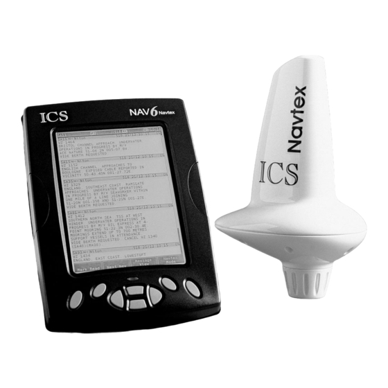
Nav6 User Guide
MAN 3008.03
Issue 1.2
ICS Electronics Limited.
Unit V, Rudford Industrial Estate
Ford, Arundel, West Sussex
BN18 0BD
United Kingdom
Tel: +44 (0)1903 731101
Fax: +44 (0)1903 731105
sales@icselectronics.co.uk
E-Mail:
support@icselectronics.co.uk
www.icselectronics.co.uk
Website:
The technical data, information and illustrations contained in this publication
were to the best of our knowledge correct at the time of going to print. We
reserve the right to change specifications, equipment, installation and
maintenance instructions without notice as part of our policy of continuous
product development and improvement. No part of this publication may be
reproduced, stored in a retrieval system or transmitted in any form, electronic
or otherwise without permission in writing from ICS Electronics Ltd. No liability
can be accepted for any inaccuracies or omissions in the publication, although
every care has been taken to make it as complete and accurate as possible.
Copyright 2001, ICS Electronics Limited. All rights reserved.
Advertisement
Table of Contents

Related Manuals for ICS Nav6


Summary of Contents for ICS Nav6
- Page 1 No part of this publication may be reproduced, stored in a retrieval system or transmitted in any form, electronic or otherwise without permission in writing from ICS Electronics Ltd. No liability can be accepted for any inaccuracies or omissions in the publication, although every care has been taken to make it as complete and accurate as possible.
-
Page 2: Important Information
Nav6 NAVTEX System User Guide Important Information This equipment is not approved for use by SOLAS convention vessels within the Global Maritime Distress and Safety System (GMDSS) It is intended for use by leisure craft and other non-SOLAS vessels wishing to participate within GMDSS... -
Page 3: Table Of Contents
Nav6 NAVTEX System User Guide Contents Quick Start..................5 Introduction..................5 How To Operate Your Nav6 ............8 NAVTEX Mode ................9 Setup Mode .................. 13 Alarm Operation................19 Installation Of Sensor Unit ............20 Installation Of Display Unit ............21 Testing The Nav6 After Installation.......... - Page 4 The support pages contain frequently asked questions about the Nav6 that you may find useful. There is also a NAVTEX database providing a list of operational NAVTEX stations and their details.
-
Page 5: Quick Start
Nav6 NAVTEX System User Guide QUICK START QUICK START QUICK START QUICK START You will find this product extremely easy to operate. Please don't be intimidated by the comprehensive nature of this manual. In reality, receiving your first NAVTEX messages just could not be simpler. - Page 6 Each station is allocated a 10-minute time slot every 4 hours so that many stations can share the same frequency. The Nav6 receiver stores all messages received from all stations. Nav6 users can set-up filtering to display only specific message types from selected stations.
- Page 7 What Can My Nav6 Do? What Can My Nav6 Do? • The Nav6 stores all correctly framed NAVTEX messages that it receives in non-volatile memory, regardless of station, message type or error rate. The messages to be displayed on the LCD can be selected from the total set of stored messages by applying various filter settings.
-
Page 8: How To Operate Your Nav6
Left Down Right The Nav6 has eight keys. The centre four of these are a ‘screen navigation’ pad (left, right, up and down). The four keys situated on either side of the navigation pad are soft-keys. Their function is context sensitive. The current function of each of the four soft-keys is shown on the soft-key menu area at the bottom of the display. -
Page 9: Navtex Mode
The MODE softkey switches between the two operating modes of the Nav6: In addition, holding down the MODE softkey for longer than 2 seconds resets the LCD contrast and backlight to 50% and selects the LCD setup page. - Page 10 Nav6 NAVTEX System User Guide Message at the top of the display An alarm is active NMEA time and date data active 490 kHz reception available 518 kHz reception available Receiving message now Signal Carrier, but no message Sensor communication fault...
- Page 11 Nav6 NAVTEX System User Guide Sort by Station orders the messages by NAVTEX frequency and the alphabetical order of their station letters. Sort by Type orders the messages in the alphabetical order of their message identifier letter. Sort by Date orders the messages by the date and time that they were first received.
- Page 12 Nav6 NAVTEX System User Guide The picture shows the 518 Types filter page; the 490 Types filter page is similar. Each of the message types can be selected as either ON, OFF or NEW. Use the UP and DOWN keys to select the message type setting that you wish to edit.
-
Page 13: Setup Mode
Nav6 NAVTEX System User Guide SETUP MODE SETUP MODE SETUP MODE SETUP MODE Setup Mode consists of 2 ‘Views’ that can be selected with the VIEW softkey. Each View has a number of ‘Pages’ that can be selected with the PAGE softkey. - Page 14 Nav6 NAVTEX System User Guide • Date and time will be taken from NMEA input data if available. • There is no battery backup so date and time will be incorrect when power is switched on unless NMEA data is available or the date and time are manually set.
- Page 15 Nav6 NAVTEX System User Guide Setup Mode, NAVTEX View, Setup Mode, NAVTEX View, Setup Mode, NAVTEX View, Setup Mode, NAVTEX View, Options Page Options Page Options Page Options Page The NAVTEX View Options Page shows general settings for NAVTEX operation such as Antenna, Display and Sound settings.
- Page 16 Nav6 NAVTEX System User Guide Option Setting Notes Antenna Antenna alarm off Alarm Timed Antenna alarms repeated 5 times, unless cancelled Repeat Antenna alarms repeated until cancelled SAR Alarm SAR alarm off Timed SAR alarms repeated 5 times, unless cancelled...
- Page 17 Nav6 NAVTEX System User Guide are receiving is the ‘S’ station in an adjacent Nav Area). Setup Mode, NAVTEX View, 518 and 490 Names, Station Setup Mode, NAVTEX View, 518 and 490 Names, Station Setup Mode, NAVTEX View, 518 and 490 Names, Station...
- Page 18 Nav6 NAVTEX System User Guide position. Use the LEFT and RIGHT keys to change the selected item. When you have finished entering the data, press the SAVE softkey to save and update the database or CANCEL softkey to abort the change.
-
Page 19: Alarm Operation
(shown as * characters). ALARM OPERATION ALARM OPERATION ALARM OPERATION ALARM OPERATION The Nav6 display contains a buzzer that can generate audible alarms for the following conditions: Option Notes New Message Alert Short beep beep. Not repeated. -
Page 20: Installation Of Sensor Unit
On a yacht, pushpit mounting is permissible. Note: due to the variety of possible mounting methods (horizontal rail, vertical rail, deck, etc) ICS do not supply the antenna mounting bracket as standard. They are readily available from most marine electronics stores. -
Page 21: Installation Of Display Unit
The Sensor Cable should not be bent through tight radii (less than 4cm). • Where the Sensor Cable passes through bulkheads or decking, rubber grommets or the optional deck gland (ICS part number 2520.08) should be used to prevent chaffing. INSTALLATION OF DISPLAY UNIT INSTALLATION OF DISPLAY UNIT... - Page 22 Remove the two screw covers from the Display Unit. • Apply a releasing agent (grease or petroleum jelly) to the rubber seal around the back of the Nav6. This will prevent the seal from sticking to the bulkhead surface over time. •...
- Page 23 BATTERY NAV-6 +12v DISPLAY BLACK BLUE SENSOR BLACK BROWN BLACK * Not connected Connecting Power Connecting Power Connecting Power Connecting Power The Nav6 NAVTEX System should be powered from a nominal 12Vdc switched supply, capable of providing a continuous 350mA.
- Page 24 Connect the BLACK wire to negative (0V) supply. • Note that vessels that require isolation may need to install a DC to DC converter (ICS part number 500.09) – if in doubt ask your dealer. • 24V vessels should install the 24V / 12V DC to DC converter (ICS part number 500.10).
- Page 25 Nav6 NAVTEX System User Guide instrument systems. However, this can normally be achieved for most systems by a skilled installer. For notes on achieving compatibility with various systems, see the Nav6 FAQ section on our web site: www.icselectronics.co.uk The Nav6 uses NMEA data to synchronise its internal clock with UTC time.
-
Page 26: Testing The Nav6 After Installation
NMEA DATA A and DATA B wires. MAINTENANCE AND TROUBLE SHOOTING MAINTENANCE AND TROUBLE SHOOTING MAINTENANCE AND TROUBLE SHOOTING MAINTENANCE AND TROUBLE SHOOTING Cleaning Cleaning Cleaning Cleaning The Nav6 NAVTEX System may be cleaned when necessary by... - Page 27 Nav6 NAVTEX System User Guide wiping with a cloth dampened with fresh water. Do not use solvents. Fault Finding Fault Finding Fault Finding Fault Finding Fault Possible cause LCD blank, RED LED Green wire connected to 12V Disconnect green wire – it should not be...
-
Page 28: Glossary
Input Fuse Input Fuse The Nav6 has a built-in resettable fuse on its 12V input. This fuse will trip if the unit due to a fault condition draws excessive currents. Power must be disconnected from the unit for 10 seconds in order for the fuse to reset. -
Page 29: Warranty
PACKING LIST AND OPTIONS PACKING LIST AND OPTIONS Packing List Packing List Packing List Packing List For the Nav6 System contents – please see the packing list enclosed. Options Options Options Options The following Nav6 ancillary parts can be purchased:... -
Page 30: Specification
Nav6 NAVTEX System User Guide SPECIFICATION SPECIFICATION SPECIFICATION SPECIFICATION Approval Standards Meets the EMC requirements of IEC 60945 Power Voltage range 10.8V to 15.6V Consumption (Typical) Backlight full 310 mA (3.8 W at 12V) Backlight off 165 mA (2.0 W at 12V) Sleep mode 115 mA (1.4 W at 12V) - Page 31 Nav6 NAVTEX System User Guide Display Unit Features 1/2vga (480x320 pixels) monochrome LCD with 4 grey levels 32 step CCFL backlighting of LCD 128 step contrast adjustment of LCD LED backlighting for keyboard RS485 serial I/O port to sensor NMEA input...
-
Page 32: Appendix I: Navtex Station Database
Nav6 NAVTEX System User Guide APPENDIX I: NAVTEX STATION DATABASE APPENDIX I: NAVTEX STATION DATABASE APPENDIX I: NAVTEX STATION DATABASE APPENDIX I: NAVTEX STATION DATABASE 518kHz NAVTEX Stations 518kHz NAVTEX Stations 518kHz NAVTEX Stations 518kHz NAVTEX Stations Area Country Name... - Page 33 Nav6 NAVTEX System User Guide Area Country Name Latitude Longitude Range (NM) South Africa Port Elizabeth 33°57'S 25°31'E Japan Yokohama 35°22'N 139°36'E Chile Valparaiso (I) 32°48'S 71°29'W Sweden Gislovshammer 55°29'N 14°19'E Bulgaria Varna 43°4'N 27°46'E Canada Sydney(Canada)(J) 46°11'N 59°54'W Japan Otaru 43°12'N...
-
Page 34: Appendix Ii: Message Type Indicators
Nav6 NAVTEX System User Guide Area Country Name Latitude Longitude Range (NM) Italy Augusta 37°14'N 15°14'E Canada Fundy (V) 43°45'N 66°10'W South Korea Chukpyon 37°3'N 129°26'E Mariana Islands Guam 13°34'N 144°50'E Ireland Valentia (Dublin) 51°27'N 9°49'W France La Garde 43°6'N 5°59'E... -
Page 35: Appendix Iii: Nmea Sentences Supported
Nav6 NAVTEX System User Guide APPENDIX III: NMEA SENTENCES SUPPORTED APPENDIX III: NMEA SENTENCES SUPPORTED APPENDIX III: NMEA SENTENCES SUPPORTED APPENDIX III: NMEA SENTENCES SUPPORTED Data Item Taken from NMEA Sentences Time RMC GGA GLL ZDA Date RMC ZDA Note that the if a data item is present in more than one sentence, then it is taken from the leftmost sentence in the table entry above. - Page 36 Nav6 NAVTEX System User Guide...
Need help?
Do you have a question about the Nav6 and is the answer not in the manual?
Questions and answers