
Related Manuals for Raymarine A50


Summary of Contents for Raymarine A50
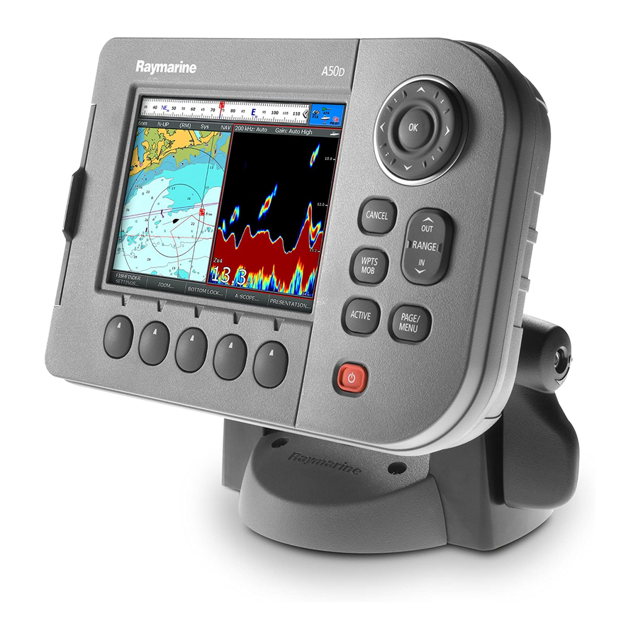
- Page 1 A-Series Multi-function display Installation instructions A50, A50D, A57D, A70 and A70D models...
- Page 2 Trademarks and registered trademarks Autohelm, HSB, RayTech Navigator, Sail Pilot, SeaTalk and Sportpi- lot are UK registered trademarks of Raymarine UK Limited. Pathfinder and Raymarine are UK registered trademarks of Rayma- rine Holdings Limited. 45STV, 60STV, AST, Autoadapt, Auto GST,...
-
Page 3: Table Of Contents
Contents Important information..........5 Sonar transducer connection ........23 NMEA 0183 connections......... 24 Warnings and Cautions ............ 5 TFT LCD displays ............. 6 SeaTalk connections ..........25 Water ingress..............6 External GPS Connection ........26 Disclaimers ............... 6 SeaTalk connections..........26 EMC installation guidelines.......... - Page 4 System data.............45 Chapter 7:Technical support ........47 Raymarine technical support ........48 Web .................48 Contacting Raymarine in the North America ....48 Contacting Raymarine in Europe........49 Navionics contact details .........49 Sirius contact details ..........50 Chapter 8:Technical Specification .......51 Technical specification..........52 Unit dimensions ............53 NMEA Messages .............54...
-
Page 5: Important Information
Raymarine dealers. This equipment must be installed in accordance Unauthorized repair may affect your warranty. with the Raymarine instructions provided. Failure to do so could result in poor product performance, CAUTION: Switch off power supply personal injury, and/or damage to your boat. -
Page 6: Tft Lcd Displays
(jet wash) equipment. official charts and documents. Raymarine does not warrant that this product is error-free or that it is compatible with products manufactured by any person or entity TFT LCD displays other than Raymarine. -
Page 7: Emc Installation Guidelines
• Place equipment more than 7ft (2 m) from the path of a radar All Raymarine equipment and accessories are designed to the best beam. A radar beam can normally be assumed to spread 20 de- industry standards for use in the recreational marine environment. -
Page 8: Declaration Of Conformity
Raymarine, a suppression ferrite must line. always be attached to the cable that is closest to the Raymarine It is important that you register your product to receive full warranty unit. - Page 9 Technical accuracy To the best of our knowledge, the information in this handbook was correct as it went to press. However, Raymarine cannot accept lia- bility for any inaccuracies or omissions it may contain. In addition, our policy of continuous product improvement may change specifi- cations without notice.
- Page 10 A-Series display - Installation instructions...
-
Page 11: Chapter 2:Planning The Installation
Chapter 2: Planning the installation This chapter provides information to help you prepare for the A-Series installation. Chapter contents • 2.1 Handbook information on page 12 • 2.2 Installation overview on page 13 • 2.3 A-Series systems on page 13 •... -
Page 12: Handbook Information
All documents can be downloaded from: www.raymarine.com/handbooks. This handbook contains important information on installing your A- Series Multifunction display and covers both freshwater and saltwa- ter variants of the following models: • A50 GPS Chartplotter • A50D GPS Chartplotter/Fishfinder • A57D GPS Chartplotter/Fishfinder •... -
Page 13: Installation Overview
Installation overview A-Series systems Your installation will include the following activities: The A-Series display can be used in a number of system types. Some examples of which are outlined in this section. Installation task Refer to Plan your system Chapter 2: Planning the Core system installation - All installation instructions... -
Page 14: Extended System
Extended system NMEA 0183 devices A-Series display Example: External AIS receiver Instrument SeaTalk devices Pilot CANCEL ENTER CANCEL ENTER MENU MENU SeaTalk NMEA SeaTalk NMEA 0183 converter Sonar SeaTalk NMEA 0183 transducer Power IN D11238-2 Your display can connect to various instruments and displays to •... - Page 15 SeaTalk The standard was specifically intended to allow for a whole network of marine electronics from any manufacturer to communicate on a SeaTalk (New Generation) is an onboard network utilizing a back- common bus via standardized message types and formats. bone cable running through the boat.
-
Page 16: Pack Contents
Pack items - All models Quick release mounting bracket R62161 All models contain the following items: Bracket fixing pack R32113 Includes screws and O-ring Suncovers A50 / A50D R62158 A57D R62159 A70 / A70D R62160 Mounting bracket Sonar cable dustcap... -
Page 17: Tools
Tools Pack items - Chartplotter / Fishfinder (D) models All chartplotter / fishfinder combination models contain the following You will need the following tools to install your display unit: additional triducer items: Triducer pack Power drill Adhesive tape D11236-1 drill bit, 35 mm (1.3/8 in) Note: The triducer supplied will be suitable for fresh or saltwater. - Page 18 A-Series display - Installation instructions...
-
Page 19: Chapter 3:Cables And Connections
Chapter 3: Cables and connections This section contains information regarding the connection of power and equipment to your A-Series display. Chapter contents • 3.1 General wiring instructions on page 20 • 3.2 Connection overview on page 21 • 3.3 Power connection on page 22 •... -
Page 20: General Wiring Instructions
• as far away from antennas as possible. • Ensure that any non-Raymarine cables are of the correct quality Strain relief and gauge. For example, longer power cable runs may require larger wire gauges to minimize any voltage drop in a cable. -
Page 21: Connection Overview
Connection overview GPS Chartplotter / Fishfinder unit (D models) The cable connections are made to the rear of the display unit. GPS Chartplotter SONAR PWR/NMEA Chart plotter / Fishfinder PWR/NMEA Chart plotter D11014-1 D11013-1 Chapter 3: Cables and connections... -
Page 22: Power Connection
The power input cable drain wires Thermal Equipment Fuse must be connected directly to the boats ground. breaker A50, A50D, A57D, A70, A70D • Use a dedicated earthing plate (e.g. dynaplate) in contact with the water. A-Series display - Installation instructions... -
Page 23: Sonar Transducer Connection
Sonar transducer connection Sonar transducer cable Fishfinder (D) models only Cable Part No Notes The A-Series is supplied with a sonar transducer. Connect this using 7.62 m (25 ft) Attached to transducer. the cable supplied. Other transducer types may be connected with flying lead the appropriate converter cable Extension cables (Small 7 way connector) -
Page 24: Nmea 0183 Connections
Part No Notes using the supplied Power/NMEA cable. 2 m (6.56 ft) R62157 Supplied with A-Series unit. A50/A57/A70 Power and NMEA Cable For other cables and accessories refer to Options and accessories on page 56 SONAR PWR/NMEA Chart plotter / Fishfinder... -
Page 25: Seatalk Connections
SeaTalk connections SeaTalk connection You can connect SeaTalk instruments to your A-Series using a SeaTalk to NMEA 0183 converter. SONAR PWR/NMEA Chart plotter / Fishfinder A-Series display A Series display SeaTalk SeaTalk instrument instrument Yellow Green SeaTalk Brown White NMEA/SeaTalk Converter SeaTalk Screen... -
Page 26: External Gps Connection
External GPS Connection SeaTalk connections The A-Series has a built in GPS antenna. If you wish to connect an Your A-Series has a rear connector for SeaTalk systems. It can external GPS antenna it may be either connected via SeaTalk or use SeaTalk to communicate with: NMEA 0183 depending upon the antenna type. -
Page 27: Nmea 2000 Connection
NMEA 2000 connection • Raymarine equipment with a regulated 12 V supply. (e.g. a SmartPilot SPX course computer) NMEA 2000 devices are connected using the SeaTalk bus. The • Other suitable 12 V supply. (Note the grounding requirements A-Series can display data received from NMEA 2000 devices (e.g. - Page 28 A-Series display - Installation instructions...
-
Page 29: Chapter 4:Location And Mounting
Chapter 4: Location and mounting This section provides instructions for siting and mounting the A-Series unit. Chapter contents • 4.1 Unit dimensions on page 30 • 4.2 Selecting a location for the unit on page 31 • 4.3 Bracket mounting on page 32 •... -
Page 30: Unit Dimensions
Unit dimensions inches 9.12 6.72 1.68 3.85 0.63 The dimensions for the A-Series Multifunction Displays are as follows: D11005-1 A50 / A50D 200.14 142.14 42.60 97.73 30.13 inches 7.88 5.60 1.68 3.85 1.20 A57D 226.64 158.64 42.60 97.73 21.88 inches 8.84... -
Page 31: Selecting A Location For The Unit
Selecting a location for the unit • Magnetic compass Select a location that is at least 3 ft (1 m) away from a magnetic compass. WARNING: Potential ignition sources • Cable runs The equipment must NOT be installed in Select a location that is as close as possible to the boat’s DC hazardous or flammable atmospheres such as an power source. -
Page 32: Bracket Mounting
Bracket mounting 2. Installing the base plate. 3. Re-assembling the bracket. 4. Installing the unit. CAUTION: Use the mounting template Preparing the bracket The unit is supplied with a mounting template, use this to locate the correct position for the bracket and its fasteners. Before the mounting bracket can be installed it is necessary to break it down into its component parts. - Page 33 To prepare the mounting bracket: 2. Mark the position of the four securing screws (8) and the cable hole. 1. Remove the four screws (1) from the cover (2) and retain for 3. Ensure that there are no cables or equipment behind the later use.
- Page 34 To re-assemble the bracket: screws. Make sure that you leave enough cable to allow connec- tion the rear of the display unit. 1. Pass the power cable and if applicable, the sonar and SeaTalk cables through the centre hole of the mounting bracket and the locking ring.
-
Page 35: Panel Mounting
Panel mounting Attaching the display to the bracket Having installed the mounting bracket, the display unit can now be Requires the optional panel mounting kit. attached to the bracket. D11010-1 To attach the display to the bracket: 1. Release the locking mechanism, by turning the lever anticlockwise. - Page 36 3. Use the hole saw to make a piot hole in each corner of the area to be cut out. 4. Use the saw to cut along the inside edge of the cut out line and join the holes in each corner. 5.
-
Page 37: Chapter 5:System Checks
Chapter 5: System checks This section contains initials checks and settings you should make once the hardware installation is complete. Chapter contents • 5.1 Initial power on test on page 38 • 5.2 External GPS setting on page 38 • 5.3 GPS Check on page 39 •... -
Page 38: Initial Power On Test
Press and hold the POWER key until the screen shows 1. Press and hold the PAGE/MENU key to open the setup menu. the Raymarine logo. 2. Use the trackpad up / down to select the Internal GPS option. 3. Use the trackpad right to open the sub-menu. -
Page 39: Gps Check
GPS Check Transducer check Select the chart page: Select the fishfinder page: 1. Press PAGE/MENU to show the available pages in the toolbar. 1. Press PAGE/MENU to show the available pages in the toolbar. 2. Press PAGE/MENU to switch between the available pages. 2. -
Page 40: Set The Language
Set the language The system can operate in the following languages: English (US) English (UK) Chinese Danish Dutch Finnish French German Greek Icelandic Italian Japanese Korean Norwegian Portuguese Russian Spanish Swedish To select a language: 1. Press and hold the PAGE/MENU key to open the setup menu. 2. -
Page 41: Chapter 6:Troubleshooting
6.2 GPS on page 43 • 6.3 Fishfinder / Sonar transducer on page 44 • 6.4 System data on page 45 See also For display software updates. Visit www.raymarine.com and follow the links to customer support and the latest soft- ware updates. -
Page 42: Power Up
Power up Problem Possible causes Possible solutions - The display does not power up. - Problem with power to the unit - Check relevant fuses and breakers. - Check that the power supply cable is sound and that all connections are tight and free from corrosion. - Check that the power source is of the correct voltage and sufficient current. -
Page 43: Gps
Problem Possible causes Possible solutions - “No Fix” GPS status icon is displayed. - External GPS antenna conflict with internal GPS - Disable internal GPS from within the setup menus. Refer to External GPS setting on page - A-Series unit in poor position to receive signal. - Move unit to a location with a better view of the sky. -
Page 44: Fishfinder / Sonar Transducer
- Transducer or connection incompatible with A- - Refer to list of compatible transducers Transducers and Series unit. associated cables on page 57 - Contact Raymarine technical support. A-Series display - Installation instructions... -
Page 45: System Data
- Data source (e.g ST70 instrument) is not - Check the source of the missing data (e.g. ST70 operating. instrument) - Refer to the manufacturers handbook for the equipment in question. - Software mismatch between equipment may - Contact Raymarine technical support prevent communication. Chapter 6: Troubleshooting... - Page 46 A-Series display - Installation instructions...
-
Page 47: Chapter 7:Technical Support
Chapter 7: Technical support This section contains information to help diagnose and correct any problems with the installations. Chapter contents • 7.1 Raymarine technical support on page 48 • 7.2 Navionics contact details on page 49 • 7.3 Sirius contact details on page 50... -
Page 48: Raymarine Technical Support
If you are unable to resolve a problem, please You can contact Raymarine in the US either using the website as use any of these facilities to obtain additional help. -
Page 49: Contacting Raymarine In Europe
Z.I. Montramito Fax: +39-0584-962696 Contacting Raymarine in Europe 55054 Massarosa Italy sales@navionics.it You can contact Raymarine in Europe either using the Raymarine Navionics 6 Thatcher Lane Toll Free: 800-848-5896 website as detailed above or by calling the telephone number below. -
Page 50: Sirius Contact Details
Sirius contact details For questions about the Sirius marine weather service, contact: www.sirius.com/marineweather 1-800-869-5480 For questions about the Sirius audio, contact: www.sirius.com 1-888-539-SIRIUS A-Series display - Installation instructions... -
Page 51: Chapter 8:Technical Specification
Chapter 8: Technical Specification Chapter contents • 8.1 Technical specification on page 52 • 8.2 Unit dimensions on page 53 • 8.3 NMEA Messages on page 54... -
Page 52: Technical Specification
Helical antenna for even antenna gain across all orientations· Waterproof to IPX6 Sirf standard library· Environmental Raymarine environmental specification WI007 category Upgradeable from host processor over serial link above deck NMEA 4800 baud, Rx: 3v3 compliant, Tx: 1v99-3v15· RTCM: Not supported·... -
Page 53: Unit Dimensions
CE approvals - Standard applied Sections 9 and 10 of EN 60945 : 2002 conforms to: EMC Compliance: D11005-1 Europe 2004/108/EC (EMC) Australia and New Zealand: C-Tick, Compliance Level 2 A50 / A50D 200.14 142.14 42.60 97.73 30.13 inches 7.88 5.60... -
Page 54: Nmea Messages
NMEA Messages A70 / A70D NMEA 0183 Input messages 233.14 170.64 42.60 97.73 15.88 APB, BWC, BWR, DBT, DPT, GLL, MTW, RMB, RMC, RTE, VHW, VLW, VTG, inches 9.12 6.72 1.68 3.85 0.63 NMEA 08183 Output messages APB, BWC, BWR, DBT, DPT, GLL, MTW, RMB, RMC, RTE, VHW, VLW, VTG, NMEA 2000 messages PGN Transmissions: 126996,126464, 129025, 129029, 129044, 129539, 129045, 129540, 129550, 129551, 126992, 129026, 1298259, 129291, 129283,... -
Page 55: Chapter 9:Accessories
Chapter 9: Accessories This section contains optional hardware and cable items and spare/replacement parts. Chapter contents • 9.1 Options and accessories on page 56 • 9.2 Spare parts on page 58... -
Page 56: Options And Accessories
Includes: 2 x 5 m Backbone cable Description Part No Notes 1 x 20m Backbone cable 4 x T-piece A50/A57/A70 Panel A62154 Optional kit required for panel 2 x Backbone terminator Mount Kit mounting. 1 x Power cable SeaTalk ng 400mm spur... -
Page 57: Transducers And Associated Cables
Transducers and associated cables Description Part No Notes The transducer is supplied with its own cable. You may use other SeaTalk ng - bare ends A06044 compatible transducers with an appropriate cable converter. 3m spur Description Part No Notes SeaTalk ng - SeaTalk 2 A06048 400mm spur Standard Transducer cables (Small 7 way connector) -
Page 58: Spare Parts
Spare parts The following replacement spares are available Item Part A50/A57/A70 Power and NMEA Cable R62157 A50 / A50D Suncover R62158 A57D Suncover R62159 A70 / A70D Suncover R62160 A50/A57/A70 Quick Release Bracket R62161 Quick release bracket fixing pack R32113... - Page 60 Raymarine plc Anchorage Park, Portsmouth, Hampshire, PO3 5TD, UK Tel: +44 (0) 23 9269 3611 Fax: +44 (0) 23 9269 4642 www.raymarine.com Raymarine Inc. 21 Manchester Street, Merrimack, New Hampshire 03054 USA, Tel: +1 603 881 5200 Fax: +1 603 864 4756...
Need help?
Do you have a question about the A50 and is the answer not in the manual?
Questions and answers