Table of Contents
Advertisement
Advertisement
Table of Contents

Subscribe to Our Youtube Channel
Related Manuals for Topcon AT-B2

Summary of Contents for Topcon AT-B2
- Page 1 取扱説明書 /INSTRUCTION MANUAL 自動レベル /AUTOMATIC LEVEL AT-B2/B3/B4 FC10386-A011-01...
- Page 2 SURVEYING INSTRUMENTS INSTRUCTION MANUAL AUTOMATIC LEVEL AT-B2/B3/B4 Thank you for selecting the AT-B2/B3/B4. • Please read this instruction manual carefully before using this product. • Verify that all equipment is included. "8. STANDARD EQUIPMENT" • The specifications and general appearance of...
-
Page 3: Table Of Contents
CONTENTS 1. PRECAUTIONS FOR SAFE OPERATION ..1 2. PRECAUTIONS ..........5 3. FEATURES OF AT-B2/B3/B4 ......7 4. PARTS OF THE INSTRUMENT ...... 8 5. PRELIMINARIES ..........9 SETTING UP THE INSTRUMENT ....9 FOCUSSING AND SIGHTING ..... 11 6. OPERATION ..........13 MEASURING HEIGHT DIFFERENCE ..13... -
Page 4: Precautions For Safe Operation
1. PRECAUTIONS FOR SAFE OPERATION For the safe use of the product and prevention of injury to operators and other persons as well as prevention of property damage, items which should be observed are indicated by an exclamation point within a triangle used with WARNING and CAUTION statements in this instruction manual. - Page 5 1. PRECAUTIONS FOR SAFE OPERATION GENERAL WARNING Never look at the sun through the telescope. Loss of eyesight could result. Do not look at reflected sunlight from a prism or other reflecting object through the telescope. Loss of eyesight could result. When securing the instrument in the carrying case make sure that all catches, including the side catches, are closed.
- Page 6 1. PRECAUTIONS FOR SAFE OPERATION TRIPOD CAUTION When mounting the instrument to the tripod, tighten the centring screw securely. Failure to tighten the screw properly could result in the instrument falling off the tripod causing injury. Tighten securely the leg fixing screws of the tripod on which the instrument is mounted.
- Page 7 1. PRECAUTIONS FOR SAFE OPERATION STAFF WARNING Do not use under thunderous weather conditions. Staff is conductive and if struck by lightning, death or injury could result. Handle with care when using near high voltage cables or transformers. Staff is conductive and contact could result in electric shock.
-
Page 8: Precautions
2. PRECAUTIONS GENERAL • The AT-B2/B3/B4 is a precision instrument. Handle with care and avoid heavy shocks and vibration. • Never place the instrument directly on the ground. • When the instrument is left on the tripod, cap the objective lens and cover the entire instrument with the vinyl cover provided. - Page 9 2. PRECAUTIONS EXCEPTIONS FROM RESPONSIBILITY • The user of this product is expected to follow all operating instructions and make periodic checks (hardware only) of the product's performance. • The manufacturer, or its representatives, assumes no responsibility for results of a faulty or intentional usage or misuse including any direct, indirect, consequential damage, and loss of profits.
-
Page 10: Features Of At-B2/B3/B4
The AT-B2/B3/B4 has been designed to allow stable surveying operations regardless of environmental conditions such as vibration and temperature changes. -
Page 11: Parts Of The Instrument
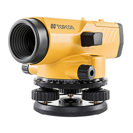
4. PARTS OF THE INSTRUMENT (Instrument shown: AT-B2) 1. Lens hood (AT-B2 only) 2. Prism (AT-B2)/Reflector (AT-B3/B4) 3. Peep sight 4. Circular level adjusting screw 5. Circular level 6. Leveling foot screw 7. Base plate 8. Horizontal fine motion screw 9. -
Page 12: Preliminaries
5. PRELIMINARIES 5.1 SETTING UP THE INSTRUMENT Unbuckle the band around the tripod legs and loosen the extension clamp screws. With the tripod closed, extend the tripod legs until the tripod head is roughly at eye level, then re- tighten the clamp screws. Spread the tripod legs so that the leg tips form a regular triangle on the ground. - Page 13 5. PRELIMINARIES Hold the instrument on the tripod head and tighten the centering screw. When using the spherical head tripod, slightly loosen the centering screw, hold the base plate in both hands, and slide it across the tripod head until the bubble is in the proximity of the circular level.
-
Page 14: Focussing And Sighting
Turn the focussing knob to focus on the target. • Focussing is coarse while the AT-B2 focussing knob feels heavy to rotate. Rotating in the reverse direction (less heavy) will give a fine focussing motion. - Page 15 2 in order to refocus the reticle. • If there is parallax, measurement errors may result, so make sure to adequately focus the target. • Use the lens hood (AT-B2 only) in strong light conditions.
-
Page 16: Operation
6. OPERATION 6.1 MEASURING HEIGHT DIFFERENCE Set up the instrument at a point approximately halfway between points A and B. The reticle stadia lines can be used to optically compare the distances. (See "6.3 MEASURING DISTANCE USING THE STADIA LINES".) •... - Page 17 6. OPERATION Therefore point B is 0.511m higher than point A. (The value of h will be negative if point B is lower than point A.) <When the distance between points A and B is large or if the height difference is great> Divide the distance into a number of sections and determine the height difference of each section.
-
Page 18: Measuring Horizontal Angle
6. OPERATION 6.2 MEASURING HORIZONTAL ANGLE The horizontal circle graduations are annotated every 10° (360°) or 10 gon (400 gon) in a clockwise direction. As a result, sighting is performed from left to right. Use the plumb bob to set up the instrument directly above the survey point. -
Page 19: Measuring Distance Using The Stadia Lines
6. OPERATION 6.3 MEASURING DISTANCE USING THE STADIA LINES The stadia lines etched on the reticle can be used for distance measurements. Sight the staff, and count the number of centimeters, , between the two stadia lines. This number is equivalent to the distance in meters between the staff and the instrument. -
Page 20: Checks And Adjustments
7. CHECKS AND ADJUSTMENTS 7.1 CIRCULAR LEVEL Adjust the leveling foot screws to center the bubble in the circular level. Turn the instrument 180° (or 200 gon). If the bubble is inside the circle, no adjustment is necessary. If the bubble shifts from within the circle, adjust as follows: Compensate for one-half of the shift by adjusting the... -
Page 21: Automatic Compensator
7. CHECKS AND ADJUSTMENTS 7.2 AUTOMATIC COMPENSATOR Center the bubble in the circular level. While turning the nearest leveling screw to the sighting axis 1/8 of a turn to the right or left, check the movement of the horizontal cross-line. (Another method is to tap the tripod legs or the main body while sighting a clear target.) If the automatic compensator mechanism is... -
Page 22: Reticle Cross-Line (Line Of Sight)
7. CHECKS AND ADJUSTMENTS 7.3 RETICLE CROSS-LINE (LINE OF SIGHT) Set the instrument halfway between two points, A and B, 30 to 50m apart. Take readings a and b Set the instrument at a point 2 m from point A. Take readings a and b Leave the telescope sighted on point B. - Page 23 7. CHECKS AND ADJUSTMENTS Unscrew and remove the adjusting screw cover. Use the adjusting pin to eliminate the difference between b ’ and b . (See "8. STANDARD EQUIPMENT".) In the example shown in step ’ is larger than b .
-
Page 24: Standard Equipment
8. STANDARD EQUIPMENT AT-B2 (Packing layout) Case: SE35A 1. Main unit ........ 1 2. Plumb bob ......1 3. Hexagonal wrench ....1 4. Adjusting pin ......2 5. Instruction manual ....1 6. Vinyl cover ......1 7. Cleaning cloth......1... - Page 25 8. STANDARD EQUIPMENT AT-B3/B4 (Packing layout) Case: SE49A 1. Main unit ........ 1 2. Plumb bob ......1 3. Hexagonal wrench ....1 4. Adjusting pin ......2 5. Instruction manual ....1 6. Vinyl cover ......1 7. Cleaning cloth......1 8.
-
Page 26: Optional Accessories
9. OPTIONAL ACCESSORIES • ILLUMINATION PACK LA8 (AT-B2 only) The illumination pack, LA8, is available for use when leveling in low light conditions. Slide it onto the telescope as far as it will go. (The lens hood should be retracted.) Switch the unit on and adjust the brightness using the knob. - Page 27 9. OPTIONAL ACCESSORIES Mount the OM5 on the telescope of the AT-B2 and push the locking lever fully forward to lock it. (The lens hood should be retracted.) Turn the micrometer knob to move the line of sight until the graduation mark on the staff comes to the middle point between the two wedge reticle lines for an accurate reading.
- Page 28 • DIAGONAL EYEPIECE DE16/DE22 The diagonal eyepiece DE16/DE22 is available for use in restricted viewing positions. DE16 for AT-B2 DE22 for AT-B3/B4 To attach the DE16, remove the eyepiece by unscrewing to the left, and screw in the diagonal eyepiece.
- Page 29 9. OPTIONAL ACCESSORIES • The AT-B2 detachable eyepiece can also be replaced by the optional 40x eyepiece (EL5). • REMOVABLE EYEPIECE EL5 (AT-B2 only) Increases the standard 32X image to 40X.
-
Page 30: Specifications
10. SPECIFICATIONS AT-B2 AT-B3 AT-B4 Telescope Length 215mm (8.46 in.) Image Erect Objective aperture 42mm 36mm 32mm (1.65 in.) (1.42 in.) (1.26 in.) Magnification ° ° Field of view (at 100m/328ft.) (2.3m/7.5ft.) (2.5m/8.2ft.) Resolving power 3.0" 3.5" 4.0" Minimum focus 0.3m (1ft.) - Page 31 Size Width 130mm (5.12in.) Length 215mm (8.46in.) Height 140mm 135mm (5.51in.) (5.31in.) Weight 1.85kg 1.7kg (4.1 lbs) (3.7 lbs)
- Page 32 This is the mark of the Japan Sur- veying Instruments Manufacturers Association.
- Page 33 Please see the attached address list or the following website for contact addresses. GLOBAL GATEWAY http://global.topcon.com/ http://www.topcon.co.jp...
Need help?
Do you have a question about the AT-B2 and is the answer not in the manual?
Questions and answers