Table of Contents
Advertisement
Advertisement
Table of Contents
Troubleshooting

Related Manuals for Yamaha DT230


Summary of Contents for Yamaha DT230
- Page 1 OWNER’S MANUAL DT230(N) 4TP-28199-21...
- Page 2 EAU00000 INTRODUCTION Congratulations on your purchase of the Yamaha DT230. This model is the result of Yamaha’s vast experience in the production of fine sporting, touring, and pacesetting racing machines. It represents the high degree of craftsmanship and reliability that have made Yamaha a leader in these fields.
-
Page 3: Important Manual Information
8 This manual should be considered a permanent part of this motorcycle and should remain with it even if the motorcycle is subsequently sold. 8 Yamaha continually seeks advancements in product design and quality. Therefore, while this manual contains the most current product information available at the time of printing, there may be minor discrepancies between your motorcycle and this manual. - Page 4 IMPORTANT MANUAL INFORMATION EW000002 PLEASE READ THIS MANUAL CAREFULLY AND COMPLETELY BEFORE OPERATING THIS MOTORCYCLE.
- Page 5 EAU03337 DT230 (N) OWNER’S MANUAL ©2000 by Yamaha Motor Co., Ltd. 1st Edition, July 2000 All rights reserved. Any reprinting or unauthorized use without the written permission of Yamaha Motor Co., Ltd. is expressly prohibited. Printed in Japan.
-
Page 6: Table Of Contents
EAU00009 TABLE OF CONTENTS SAFETY INFORMATION........1-1 Starter (choke) lever “1”........3-10 Safe riding............1-1 Seat ..............3-10 Protective apparel ..........1-3 Helmet holder ..........3-11 Modification............1-3 Adjusting the front fork ........3-11 Loading and accessories ........1-3 Adjusting the shock absorber assembly ..3-12 Gasoline and exhaust gas ........1-5 YPVS ..............3-15 Location of important labels ......1-7 Sidestand ............3-16... - Page 7 TABLE OF CONTENTS Removing and installing panels ......6-6 Checking and lubricating the brake and clutch Checking the spark plug ........6-7 levers ............6-29 Transmission oil ..........6-9 Checking and lubricating the sidestand ..6-29 Coolant ............6-10 Lubricating the rear suspension......6-30 Changing the coolant ........6-12 Checking the front fork........6-30 Cleaning the air filter element ......6-14 Checking the steering ........6-31...
- Page 8 TABLE OF CONTENTS CONSUMER INFORMATION......9-1 Identification numbers record ......9-1 Key identification number .........9-1 Vehicle identification number ......9-1 Model label ............9-2 Motorcycle noise regulation (for Australia) ..9-2...
-
Page 9: Safety Information
EAU00017 Q SAFETY INFORMATION MOTORCYCLES ARE SINGLE TRACK VEHICLES. THEIR SAFE USE AND OPERATION ARE DEPENDENT UPON THE USE OF PROPER RIDING TECHNIQUES AS WELL AS THE EXPER- TISE OF THE OPERATOR. EVERY OPERATOR SHOULD KNOW THE FOLLOWING REQUIRE- MENTS BEFORE RIDING THIS MOTORCYCLE. HE OR SHE SHOULD: 1. - Page 10 Q SAFETY INFORMATION 4. Many accidents involve inexperienced operators. In fact, many operators who have been involved in accidents do not even have a current motorcycle license. a. Make sure that you are qualified and that you only lend your motorcycle to other qualified oper- ators.
-
Page 11: Protective Apparel
6. Passengers should also observe the precautions mentioned above. Modifications Modifications made to this motorcycle not approved by Yamaha, or the removal of original equipment, may render the motorcycle unsafe for use and may cause severe personal injury. Modifications may also make your motorcycle illegal to use. - Page 12 Genuine Yamaha accessories have been specifically designed for use on this motorcycle. Since Yamaha cannot test all other accessories that may be available, you must personally be responsible for the proper selection, installation and use of non-Yamaha accessories. Use extreme caution when selecting and installing any accessories.
-
Page 13: Gasoline And Exhaust Gas
Q SAFETY INFORMATION 1. Never install accessories or carry cargo that would impair the performance of your motorcycle. Carefully inspect the accessory before using it to make sure that it does not in any way reduce ground clearance or cornering clearance, limit suspension travel, steering travel or control opera- tion, or obscure lights or reflectors. - Page 14 Q SAFETY INFORMATION 2. Never start the engine or let it run for any length of time in a closed area. The exhaust fumes are poisonous and may cause loss of consciousness and death within a short time. Always operate your motorcycle in an area that has adequate ventilation.
-
Page 15: Location Of Important Labels
Q SAFETY INFORMATION EAU02977 Location of important labels Please read the following important labels carefully before operating this motorcycle. WARNING Before you operate this vehicle, read the owner’s manual. English 3HP-21568-00 4AA-22259-40... -
Page 17: Description
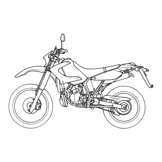
EAU00026 DESCRIPTION Left view 2 3 4 1. Headlight (page 6-34) 8. Rear shock absorber spring preload 2. Rear shock absorber compression adjusting nut (page 3-13) damping adjusting knob (page 3-14) 9. Rear shock absorber rebound damping 3. Fuel cock (page 3-9) adjusting dial (page 3-14) -
Page 18: Right View
DESCRIPTION Right view 15 16 13. Coolant reservoir (page 6-11) 14. Owner’s tool kit (page 6-1) 15. Battery (page 6-32) 16. Fuse (page 6-33) 17. Radiator cap (page 6-12) 18. Brake pedal (page 3-7, 6-22) -
Page 19: Controls And Instruments
DESCRIPTION Controls and instruments 1. Clutch lever (page 3-6, 6-20) 6. Brake lever (page 3-6, 6-21) 2. Left handlebar switches (page 3-5) 7. Throttle grip (page 6-16, 6-28) 3. Speedometer unit (page 3-3) 8. Fuel tank cap (page 3-7) 4. Main switch/steering lock (page 3-1) 5. -
Page 20: Instrument And Control Functions
EAU00027 INSTRUMENT AND CONTROL FUNCTIONS EW000016 Never turn the key to “OFF” or “LOCK” while the motorcycle is moving, otherwise the electrical systems will be switched off, which may result in loss of control LOCK or an accident. Make sure that the motorcycle is stopped before turn- ing the key to “OFF”... -
Page 21: Indicator And Warning Lights
INSTRUMENT AND CONTROL FUNCTIONS 8 When the coolant temperature is If the warning light does not come on, too high, the warning light comes have a Yamaha dealer inspect the on and symbol “ ” flashes. electrical circuit. Stop the motorcycle and allow it... -
Page 22: Speedometer Unit
INSTRUMENT AND CONTROL FUNCTIONS When in mode “A”: 8 The upper tripmeter can be reset to zero. 8 The display can be switched between clock odometer. 8 The clock can be set. When in mode “B”: 1. Oil level/coolant temperature warning 1. - Page 23 INSTRUMENT AND CONTROL FUNCTIONS Mode “A” Mode “B” To set the upper tripmeter to zero, To set the lower tripmeter to zero, push the reset button for at least one push the reset button for at least one second. second. To display the clock or odometer To switch the tripmeter between for- reading, push the mode select button...
-
Page 24: Handlebar Switches
INSTRUMENT AND CONTROL FUNCTIONS EAU00129 Horn switch “*” Press this switch to sound the horn. 1. Dimmer switch 1. Engine stop switch 2. Turn signal switch 2. Start switch “,” 3. Horn switch “*” EAU00138 EAU00118 Engine stop switch Handlebar switches Set this switch to “$”... -
Page 25: Clutch Lever
INSTRUMENT AND CONTROL FUNCTIONS 1. Clutch lever 1. Shift pedal 1. Brake lever N. Neutral EAU00152 EAU00158 EAU00157 Clutch lever Brake lever Shift pedal The clutch lever is located at the left The brake lever is located at the right The shift pedal is located on the left handlebar grip. -
Page 26: Brake Pedal
INSTRUMENT AND CONTROL FUNCTIONS NOTE: The fuel tank cap cannot be installed unless the key is in the lock. In addi- tion, the key cannot be removed if the cap is not properly installed and locked. EW000023 1. Brake pedal 1. -
Page 27: Fuel
INSTRUMENT AND CONTROL FUNCTIONS EAU00185 Immediately wipe off spilled fuel with a clean, dry, soft cloth, since fuel may deteriorate painted sur- faces or plastic parts. EAU00192 Recommended fuel: 1. Filler tube 1. 2-stroke engine oil tank cap 2. Fuel level 2. -
Page 28: Fuel Cock
INSTRUMENT AND CONTROL FUNCTIONS NOTE: OFF: Closed position ON: Normal position Make sure that the 2-stroke engine oil tank cap is properly closed. FUEL Recommended oil: FUEL Yamalube 2 or equivalent 2-stroke engine oil (JASO grade “FC”) 1. Arrow mark positioned over “OFF” 1. -
Page 29: Starter (Choke) Lever "1
INSTRUMENT AND CONTROL FUNCTIONS RES: Reserve position FUEL 1. Starter (choke) lever “1” 1. Bolt (×2) 1. Arrow mark positioned over “RES” EAU02976 EAU00240 Starter (choke) lever “1” Seat This indicates reserve. If you run out Starting a cold engine requires a rich- To remove the seat of fuel while riding, move the lever to er air-fuel mixture, which is supplied... -
Page 30: Helmet Holder
INSTRUMENT AND CONTROL FUNCTIONS EAU03589 Adjusting the front fork This front fork is equipped with damp- ing force adjusting screws. EW000035 Always adjust both fork legs equally, otherwise poor handling and loss of stability may result. 1. Projection (×2) 1. Helmet holder 2. -
Page 31: Adjusting The Shock Absorber Assembly
INSTRUMENT AND CONTROL FUNCTIONS EAU03672 17 clicks in direction b* Minimum (soft) Adjusting the shock 14 clicks in direction b* Standard absorber assembly 1 click in direction b* Maximum (hard) This shock absorber assembly is * With the adjusting screw fully turned in direction a equipped with spring... - Page 32 INSTRUMENT AND CONTROL FUNCTIONS Spring preload: Minimum (soft): Distance A = 252 mm Standard: Distance A = 244 mm Maximum (hard): Distance A = 234 mm 3. Tighten the locknut to the speci- 1. Adjusting nut 1. Special wrench 2. Locknut fied torque.
- Page 33 INSTRUMENT AND CONTROL FUNCTIONS NOTE: Although the total number of clicks of a damping force adjusting mecha- nism may not exactly match the above specifications due to small dif- ferences in production, the actual number of clicks always represents the entire adjusting range. To obtain a precise adjustment, it would be 1.
-
Page 34: Ypvs
This shock absorber contains sophisticated adjustment, have a highly pressurized nitrogen gas. Yamaha dealer, who has the neces- For proper handling, read and sary professional knowledge and understand the following informa- experience, make this adjustment. tion before handling the shock EC000023 absorber. -
Page 35: Sidestand
8 It It cuts the running engine when regularly as described below and the sidestand is moved down. have a Yamaha dealer repair it if it Periodically check the operation of does not function properly. the ignition circuit cut-off system according to the following procedure. - Page 36 5. Push the start switch. Does the engine start? The neutral switch may be defective. The motorcycle should not be ridden until checked by a Yamaha dealer. With the engine still running: 6. Move the sidestand up. 7. Keep the clutch lever pulled.
-
Page 37: Pre-Operation Checks
• If necessary, add recommended coolant to specified level. 6-10–6-13 • Check cooling system for leakage. • Check operation. • If soft or spongy, have Yamaha dealer bleed hydraulic system. • Check lever free play. Front brake • Adjust if necessary. - Page 38 PRE-OPERATION CHECKS ITEM CHECKS PAGE • Check operation. • Lubricate cable if necessary. Clutch 3-6, 6-20–6-21 • Check lever free play. • Adjust if necessary. • Make sure that operation is smooth. • Lubricate throttle grip, housing and cable if necessary. Throttle grip 6-16–6-17, 6-28 •...
- Page 39 • Check operation of ignition circuit cut-off system. Sidestand switch 3-16–3-17 • If system is defective, have Yamaha dealer check vehicle. NOTE: Pre-operation checks should be made each time the motorcycle is used. Such an inspection can be accomplished in a very short time;...
-
Page 40: Operation And Important Riding Points
EW000054 length of time. Exhaust fumes Yamaha dealer check the electrical are poisonous, and inhaling circuit. 8 Before starting the engine, them can cause loss of con-... -
Page 41: Starting A Warm Engine
OPERATION AND IMPORTANT RIDING POINTS EAU01258 NOTE: Starting a warm engine If the engine fails to start, release the Follow the same procedure as for start switch, wait a few seconds, and starting a cold engine with the excep- then try again. Each starting attempt tion that the starter (choke) is not should be as short as possible to pre- required when the engine is warm. -
Page 42: Tips For Reducing Fuel Consumption
OPERATION AND IMPORTANT RIDING POINTS EC000048 EAU00424 EAU00436 Tips for reducing fuel Engine break-in consumption There is never a more important peri- 8 Even with the transmission in Fuel consumption depends largely on od in the life of your engine than the the neutral position, do not your riding style. -
Page 43: Parking
8 Vary the engine speed from time during the engine break-in period, to time. Do not operate the 8 Since the engine and exhaust immediately have a Yamaha dealer engine at one set throttle posi- system can become very hot, check the vehicle. -
Page 44: Periodic Maintenance And Minor Repair
If you do not have the tools or experi- Periodic inspection, adjustment and ence required for a particular job, lubrication will keep your vehicle in have a Yamaha dealer perform it for the safest and most efficient condi- you. tion possible. The most important... -
Page 45: Periodic Maintenance And Minor Repair
8 The annual checks must be performed every year, except if a kilometer-based maintenance is performed instead. 8 From 30,000 km, repeat the maintenance intervals starting from 6,000 km. 8 Items marked with an asterisk should be performed by a Yamaha dealer as they require special tools, data and technical skills. - Page 46 PERIODIC MAINTENANCE AND MINOR REPAIR ODOMETER READING (×1,000 km) ANNUAL ITEM CHECK OR MAINTENANCE JOB CHECK • Check tread depth and for damage. • Replace if necessary. √ √ √ √ Tires • Check air pressure. • Correct if necessary. √...
- Page 47 PERIODIC MAINTENANCE AND MINOR REPAIR ODOMETER READING (×1,000 km) ANNUAL ITEM CHECK OR MAINTENANCE JOB CHECK √ √ √ √ √ √ • Check oil level and vehicle for leakage. Transmission oil √ √ • Change. √ √ √ √ √...
-
Page 48: Removing And Installing Cowlings
PERIODIC MAINTENANCE AND MINOR REPAIR 1. Cowling A 1. Screw (×4) 1. Screw (×3) 2. Cowling B EAU00484 EAU00482 Cowling B EAU01065 Cowling A Removing and installing To remove the cowling To remove the cowling cowlings Remove the screws, and then take Remove the cowling screws, and The cowlings shown above need to the cowling off. -
Page 49: Removing And Installing Panels
PERIODIC MAINTENANCE AND MINOR REPAIR 1. Panel A 1. Panel B 1. Screw EAU01122 EAU00488 Refer to this section each time a Removing and installing Panel A panel needs to be removed and panels To remove the panel installed. The panels shown above need to be Remove the screw, and then pull the removed to perform some of the panel off as shown. -
Page 50: Checking The Spark Plug
PERIODIC MAINTENANCE AND MINOR REPAIR 1. Screw 1. Spark plug cap 1. Spark plug wrench EAU00488 EAU01833 2. Remove spark plug Checking the spark plug Panel B shown, with the spark plug The spark plug is an important To remove the panel wrench included in the owner’s engine component, which is easy to Remove the screw, and then pull the... - Page 51 Instead, 1. Measure the spark plug gap with soon as possible. have a Yamaha dealer check the a wire thickness gauge and, if motorcycle. necessary, adjust the gap to 4. Install the spark plug cap. specification. 2. Check the spark plug for elec-...
-
Page 52: Transmission Oil
PERIODIC MAINTENANCE AND MINOR REPAIR EAU03109 Transmission oil Oil level inspection 1. Place the motorcycle on a level place and hold it in an upright position. Warm up the engine for several minutes. NOTE: Be sure the motorcycle is positioned 1. -
Page 53: Coolant
PERIODIC MAINTENANCE AND MINOR REPAIR EAU01808 Recommended oil: Coolant See page 8-1. To check the coolant level Oil quantity: 1. Place the motorcycle on a level Total amount: 0.85 L surface and hold it in an upright Periodic oil change: 0.8 L position. - Page 54 8 If water has been added to the The coolant should be between the minimum and maximum level marks. coolant, have a Yamaha dealer check the antifreeze content of the coolant as soon as possi- 4. If the coolant is at or below the...
-
Page 55: Changing The Coolant
PERIODIC MAINTENANCE AND MINOR REPAIR 1. Radiator cap stopper bolt 1. Coolant drain bolt 1. Maximum level mark 2. Radiator cap 2. Minimum level mark 4. Place a container under the 3. Reservoir tank hose EAU03101 engine and remove the coolant Changing the coolant 5. - Page 56 If any leakage is found, ask a 0.36 L 8 If water has been added to the Yamaha dealer to inspect the cooling coolant, have a Yamaha dealer system. check the antifreeze content of the coolant as soon as possi- 15.
-
Page 57: Cleaning The Air Filter Element
PERIODIC MAINTENANCE AND MINOR REPAIR 1. Screw (×3) 1. Air filter element guide 2. Air filter case cover 2. Air filter element frame 3. Pull the air filter element out from 3. Sponge material EAU03671 4. Wing nut the air filter case. Cleaning the air filter 4. -
Page 58: Adjusting The Carburetor
Therefore, most wing nut. carburetor adjustments should be left 9. Insert the air filter element into to a Yamaha dealer, who has the the air filter case. necessary professional knowledge EC000082 experience. -
Page 59: Adjusting The Engine Idling Speed
NOTE: adjusting the throttle cable free play. The engine is warm when it quickly NOTE: responds to the throttle. If the specified idling speed cannot be obtained as described above, have a Yamaha dealer make the adjustment. 6-16... -
Page 60: Tires
PERIODIC MAINTENANCE AND MINOR REPAIR EAU03593 Tire air pressure Tires (measured on cold tires) Load* Front Rear To maximize the performance, dura- 125 kPa 150 kPa bility, and safe operation of your Up to 88 kg 1.25 kg/cm 1.50 kg/cm motorcycle, note the following points 1.25 bar 1.50 bar... - Page 61 Yamaha dealer replace the tire imme- 8 Do not carry along loosely diately. packed items, which can shift Minimum tire tread depth 1.0 mm...
- Page 62 PERIODIC MAINTENANCE AND MINOR REPAIR EW000079 EW000078 EAU00680 8 Have a Yamaha dealer replace 8 The front and rear tires should 8 It is dangerous to ride with a excessively worn tires. be of the same make and worn-out tire. When a tire...
-
Page 63: Spoke Wheels
Clutch lever free play each ride. If any damage is EAU02996 Adjusting the clutch lever found, have a Yamaha dealer free play replace wheel. The clutch lever free play should attempt even the smallest repair measure 10–15 mm as shown. -
Page 64: Adjusting The Brake Lever Free Play
PERIODIC MAINTENANCE AND MINOR REPAIR 4. Fully turn the adjusting bolt in direction a to loosen the clutch cable. 5. Loosen the locknut further down the clutch cable. 6. To increase the clutch lever free play, turn the adjusting nut in direction a. -
Page 65: Adjusting The Brake Pedal Position
If there is air in the hydraulic sys- 8 A soft or spongy feeling in the tem, have a Yamaha dealer bleed brake lever can indicate the the system before operating the presence motorcycle. -
Page 66: Adjusting The Rear Brake Light Switch
The rear brake light switch, which is be checked for wear at the intervals appeared, have a Yamaha dealer activated by the brake pedal, is prop- specified in the periodic maintenance replace the brake pads as a set. -
Page 67: Checking The Brake Fluid Level
A low ing leakage and poor braking suddenly, have a Yamaha dealer brake fluid level may indicate worn performance. check the cause. brake pads and/or brake system leakage. -
Page 68: Changing The Brake Fluid
PERIODIC MAINTENANCE AND MINOR REPAIR EAU03073 EAU00744 Changing the brake fluid Drive chain slack Have a Yamaha dealer change the The drive chain slack should be brake fluid at the intervals specified in checked before each ride and adjust- the periodic maintenance and lubrica- ed if necessary. -
Page 69: Lubricating The Drive Chain
PERIODIC MAINTENANCE AND MINOR REPAIR EC000096 EAU03006 Lubricating the drive chain The drive chain must be cleaned and Improper drive chain slack will lubricated at the intervals specified in overload the engine as well as the periodic maintenance and lubrica- other vital parts of the motorcycle tion chart, otherwise it will quickly and can lead to chain slippage or... -
Page 70: Checking And Lubricating The Cables
If a cable is damaged or does not move smoothly, have a Yamaha dealer check or replace it. Recommended lubricant: Engine oil 6-27... -
Page 71: Checking And Lubricating The Throttle Grip And Cable
Recommended lubricant: and the cable should be lubricated or Yamaha dealer at the intervals speci- Throttle cable: replaced if necessary. fied in the periodic maintenance and Engine oil lubrication chart. -
Page 72: Checking And Lubricating The Brake And Shift Pedals
Recommended lubricant: Recommended lubricant: EW000113 Lithium-soap-based grease Lithium-soap-based grease If the sidestand does not move up (all-purpose grease) (all-purpose grease) down smoothly, have Yamaha dealer check or repair it. Recommended lubricant: Lithium-soap-based grease (all-purpose grease) 6-29... -
Page 73: Lubricating The Rear Suspension
Recommended lubricant: rebounds smoothly. Molybdenum disulfide grease EC000098 If any damage is found or the front fork does not operate smoothly, have a Yamaha dealer check or repair it. 6-30... -
Page 74: Checking The Steering
Yamaha 1. Place a stand under the engine dealer check the wheel bearings. to raise the front wheel off the ground. -
Page 75: Battery
To charge the battery severe burns. Avoid any con- Have a Yamaha dealer charge the tact with skin, eyes or clothing battery as soon as possible if it and always shield your eyes seems to have discharged. -
Page 76: Replacing The Fuse
Yamaha dealer charge your 1. Turn the key to “OFF” and turn nals. battery. off all electrical circuits. 2. Remove the blown fuse, and then install a new fuse of the specified amperage. -
Page 77: Replacing The Headlight Bulb
1. Headlight coupler the electrical circuits to check if 2. Disconnect the headlight cou- the devices operate. pler, and then remove the head- 4. If the fuse immediately blows light bulb cover. again, have a Yamaha dealer check the electrical system. 6-34... - Page 78 PERIODIC MAINTENANCE AND MINOR REPAIR 1. Headlight bulb cover 1. Headlight bulb holder a. Do not touch this area EC000106 3. Unhook the headlight bulb hold- er, and then remove the defec- Avoid touching the glass part of tive bulb. the bulb.
-
Page 79: Replacing A Turn Signal Light Bulb
PERIODIC MAINTENANCE AND MINOR REPAIR 6. Install the cowling together with the headlight unit. 7. Have a Yamaha dealer adjust the headlight beam if necessary. 1. Screw 1. Bulb 2. Lens 2. Remove the defective bulb by EAU03497 Replacing a turn signal light... -
Page 80: Replacing The Tail/Brake Light Bulb
PERIODIC MAINTENANCE AND MINOR REPAIR 1. Screw (×2) 1. Bulb 1. Nut (×2) 2. Lens EAU01624 2. Remove the defective bulb by EAU01623 Replacing the license plate Replacing the tail/brake light pushing it in and turning it coun- light bulb bulb terclockwise. -
Page 81: Supporting The Motorcycle
PERIODIC MAINTENANCE AND MINOR REPAIR EAU01579 Supporting the motorcycle Since this model is not equipped with a centerstand, follow these precau- tions when removing the front and rear wheel or performing other main- tenance requiring the motorcycle to stand upright. Check that the motor- cycle is in a stable and level position before starting any maintenance. -
Page 82: Front Wheel
EAU00879 Front wheel To remove the front wheel EW000122 8 It is advisable to have a Yamaha dealer service the wheel. 8 Securely support the motorcy- cle so that there is no danger of it falling over. 1. Loosen the wheel axle holder nuts, then the wheel axle. -
Page 83: Rear Wheel
4. Tighten the wheel axle to the 8 It is advisable to have a specified torque. Yamaha dealer service the Tightening torque: wheel. Wheel axle: 8 Securely support the motorcy- 58 Nm (5.8 m cle so that there is no danger of it falling over. - Page 84 PERIODIC MAINTENANCE AND MINOR REPAIR EAU01806 To install the rear wheel 1. Install the drive chain onto the rear sprocket, and then insert the wheel axle from the left side. NOTE: Make sure that there is enough space between brake pads before inserting...
-
Page 85: Troubleshooting
Use only genuine Yamaha replace- ment parts. Imitation parts may look like Yamaha parts, but they are often inferior, have a shorter service life and can lead to expensive repair bills. 6-42... -
Page 86: Troubleshooting Charts
2. Compression There is compression. Go to ignition check. Use electric starter. No compression. Ask a Yamaha dealer to inspect. 3. Ignition Wipe clean with dry cloth and correct Open throttle half-way and start Wet. Remove spark spark gap or replace spark plug. - Page 87 Restart the engine. If the engine overheats again, ask a Level is OK. Yamaha dealer to inspect and repair the cooling system. NOTE: If coolant is not available, tap water can be temporarily used instead, provided that it is changed to the recommended coolant as soon as possible.
-
Page 88: Motorcycle Care And Storage
EAU03521 MOTORCYCLE CARE AND STORAGE Care Before cleaning Cleaning 1. Cover the muffler outlet with a ECA00010 While the open design of a motorcy- plastic bag after the engine has cle reveals the attractiveness of the 8 Avoid using strong acidic cooled down. - Page 89 MOTORCYCLE CARE AND STORAGE 8 Do not use any harsh chemical 8 For motorcycles equipped After riding in the rain, near the sea products on plastic parts. Be with a windshield: Do not use or on salt-sprayed roads sure to avoid using cloths or strong cleaners hard...
- Page 90 4. To prevent corrosion, it is recom- NOTE: cle test its braking perfor- mended to apply a corrosion pro- Consult a Yamaha dealer for advice mance and cornering behav- on what products to use. tection spray on all metal, includ- ior.
-
Page 91: Storage
MOTORCYCLE CARE AND STORAGE Storage Long-term c. Install the spark plug cap onto Before storing your motorcycle for Short-term the spark plug, and then place several months: Always store your motorcycle in a the spark plug on the cylinder 1. Follow all the instructions in the cool, dry place and, if necessary, pro- head so that the electrodes “Care”... - Page 92 MOTORCYCLE CARE AND STORAGE 6. Lubricate all control cables and 9. Remove the battery and fully the pivoting points of all levers charge it. Store it in a cool, dry and pedals as well as of the place and charge it once a sidestand/centerstand.
-
Page 93: Specifications
EAU01038 SPECIFICATIONS Specifications Model DT230(N) Engine oil Dimensions Type 2-stroke engine oil Overall length 2,225 mm Capacity Overall width 800 mm Total amount 1.3 L Overall height 1,200 mm Transmission oil Seat height 865 mm Type SAE 10W30 type SE motor oil... - Page 94 SPECIFICATIONS Spark plug Tires Manufacturer/model NGK/BR9ES Type With tube 0.7–0.8 mm Front Clutch type Wet, multiple-disc Size 3.00-21 51P Transmission Manufacturer/ INOUE/GP-21F model CHENG SHIN/M-6033 Primary reduction system Helical gear Rear Primary reduction ratio 54/21 (2.571) Size 4.60-18 63P Secondary reduction system Chain drive Manufacturer/ INOUE/GP-22R...
- Page 95 SPECIFICATIONS Wheels Spring/shock absorber Front Front Coil spring/oil damper Type Spoke wheel Rear Coil-gas spring/oil damper 1.60 × 21 Size Wheel travel Rear Front 250 mm Type Spoke wheel Rear 240 mm 2.15 × 18 Size Electrical system Brakes Ignition system C.D.I.
- Page 96 SPECIFICATIONS 12 V, 3W × 1 Neutral indicator light 12 V, 3W × 1 High beam indicator light 12 V, 3W × 1 Turn signal indicator light Oil level/coolant temperature warning light Fuse...
-
Page 97: Conversion Table
SPECIFICATIONS EAU01064 Conversion table CONVERSION TABLE All specification data in this manual are listed in SI and METRIC TO IMPERIAL METRIC UNITS. Metric unit Multiplier Imperial unit Use this table to convert METRIC unit data to m • kg 7.233 ft •... -
Page 98: Consumer Information
Record the key identification number, vehicle identification number and model label information in the spaces provided below for assistance when ordering spare parts from a Yamaha dealer or for reference in case the vehicle is stolen. 1. KEY IDENTIFICATION 1. Key identification number 1. -
Page 99: Model Label
This information will be the ultimate purchaser or while it needed when ordering spare parts is in use; and from a Yamaha dealer. (b) The use of the vehicle after such device or element of design has been removed or rendered inop-... - Page 102 YAMAHA MOTOR CO., LTD. PRINTED ON RECYCLED PAPER PRINTED IN JAPAN 2000·7–0.1×1(E)